UNIT 6
Basics of Manufacturing Processes and Measurements
The manufacturing processes can be classified as:
1. Forming Processes
2. Moulding Processes
3. Machining Processes
4. Assembly Processes
5. Finishing Processes.
1. Forming Processes:
In the metal industry, some of the primary forming operations may take place such as the rolling of basic shapes in steel, aluminium etc. Some of the common shapes so obtained from these processes are bars, sheets, billets, I-beams etc. Which are standard shapes. These shapes can be used for further processing. Other forming processes may be drop-forging, stamping, extrusion, press work, punching, drawing etc.
2. Moulding Processes:
Some products require moulding processes such as sand casting, die-casting etc. to get basic shape or form which may or may not require further processing. The selection of the particular process will depend upon to size of the job, quantity to be produced, accuracy, and complexity desired and economy.
3. Machining Processes:
Metal machining is accomplished through basic machine tool processes which involve the generation of cylindrical surfaces, flat surfaces, complex curves and holes. The machine tools selected to accomplish this task depend on the size and shape of the part to be machined, the quality of finish required and production rate required.
The examples of such processes are: turning, shaping, drilling, boring, grinding etc. In these machining operations metal is removed from the part in the form of small chips by the cutting action of tool. The cutting action is accomplished by either rotating or reciprocating action of the tool relating to the part.
4. Assembly Processes:
These processes assemble the parts and materials using welding, riveting, soldering, brazing, mechanical fastening and adhesive joining etc.
5. Finishing Processes:
These processes are carried out for the aesthetic aspects, to achieve accuracy, surface finish or to increase life of the product. Such processes include cleaning, blasting, deburring, puffing, honing, lapping, polishing, painting etc.
Primary shaping processes are manufacturing of a product from an amorphous material. Some processes produces finish products or articles into its usual form whereas others do not, and require further working to finish component to the desired shape and size. Castings need re-melting of scrap and defective ingots in cupola or in some other melting furnace and then pouring of the molten metal into sand or metallic moulds to obtain the castings. Thus the intricate shapes can be manufactured. Typical examples of the products that are produced by casting process are machine beds, automobile engines, carburettors, flywheels etc. The parts produced through these processes may or may not require to undergo further operations. Some of the important primary shaping processes is
(1) Casting,
(2) Powder metallurgy,
(3) Plastic technology,
(4) Gas cutting,
(5) Bending and
(6) Forging.
Metal cutting is “the process of removing unwanted material in the form of chips, from a block of metal, using cutting tool”. A person who specializes in machining is called a machinist. A room, building or company where machining is done is called a Machine Shop.
The basic elements involved in this process are:
(i) A block of metal (work piece).
(ii) Cutting Tool.
(iii) Machine Tool.
(iv)Cutting Fluid.
(v) Cutting speed (Primary Motion).
(vi)Feed (Secondary Motion).
(vii) Chips.
(viii) Work holding and Fixturing.
(ix) Force and Energy Dissipated, and
(x) Surface Finish.
The essential conditions for successful metal cutting are:
(a) Relative motion between work and cutting tool.
(b) Tool material must be harder than work material.
(c) Work and tool must be rigidly held by jig and fixtures.
(d) Sharp Cutting edge of cutting tool.
(e) Primary Motion (Cutting Speed).
(f) Secondary Motion (Cutting Feed).
(g) Almost all the products produced by metal removal process, either directly or indirectly. The major disadvantages of the process are loss of material in the form of chips.
Types of Cutting Processes (Operations):
Machining is not just one process; it is a group of processes. There are many kinds of machining operations. Each of which is specialized to generate a certain part geometry and surface finish quality.
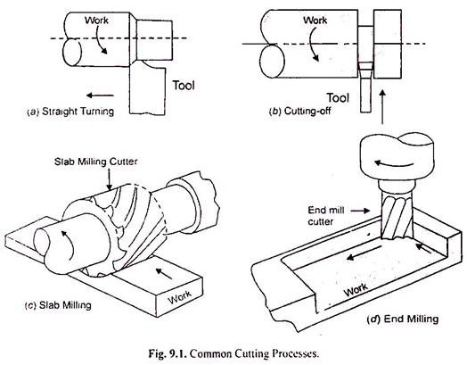
Some of the more common cutting processes are shown in Fig. 9.1:
(i) Turning:
Turning is used to generate a cylindrical shape. In this process, the work piece is rotated and cutting tool removes the unwanted material in the form of chips. The cutting tool has single cutting edge. The speed motion is provided by the rotating work piece, and the feed motion is achieved by the cutting tool moving slowly in a direction parallel to the axis of rotation of the work piece.
(ii) Drilling:
Drilling is used to create a round hole. In this process, the cutting tool is rotated and feed against the work piece fixed in a holding device. The cutting tool typically has two or more cutting edges. The tool is fed in a direction parallel to its axis of rotation into the work piece to form the round hole.
(iii) Boring:
Boring is used to enlarge an already drilled hole. It is a fine finishing operation used in the final stage of product manufacture.
(iv) Milling:
Milling is used to remove a layer of material from the work surface. It is also used to produce a cavity in the work surface. In the first case it is known as slab-milling and in second case it is known as end- milling. Basically, the milling process is used to produce a plane or straight surface. The cutting tool used has multiple cutting edges. The speed motion is provided by the rotating milling cutter. The direction of the feed motion is perpendicular to the tool’s axis of rotation.
(v) Cutting-Off:
Cutting-off is used to cut the metal into two parts. In this operation, the work piece is rotated and cutting tool moves radially inward to separates the components.
Methods of Metal Cutting:
There are two basic methods of metal cutting based on cutting edge and direction of relative motion between tool and work:
(i) Orthogonal cutting process (Two Dimensional)
(ii) Oblique cutting process (Three Dimensional)
(i) Orthogonal Cutting Process:
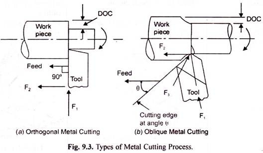
In orthogonal cutting process, the cutting edge is perpendicular (90 degree) to the direction of feed. The chip flows in a direction normal to cutting edge of the tool. A perfectly sharp tool will cut the metal on rack surface.
The orthogonal cutting process is shown in Fig. 9.3. (a):
(ii) Oblique Cutting Process:
In oblique cutting process, the cutting edge is inclined at an acute angle (less than 90 degree) to the direction of feed. The chip flows sideway in a long curl. The chip flows in a direction at an angle with normal to the cutting edge of the tool.
Principle of Metal Cutting:
A typical metal cutting process by single point cutting tool is shown in Fig. 9.2. In this process, a wedge shaped tool moves relative to the work piece at an angle a. As the tool makes contact with the metal, it exerts pressure on it. Due to the pressure exerted by the tool tip, metal will shear in the form of chips on the shear plane AB. A chip is produced ahead of the cutting tool by deforming and shearing the material continuously, along the shear plane AB.
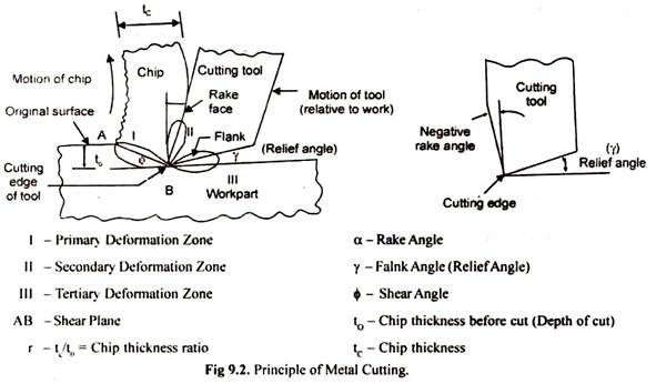
The shear plane is actually a narrow zone and extends from the cutting edge of the tool to the surface of the work piece. The cutting edge of the tool is formed by two intersecting surfaces.
A detailed about various terminologies is given below:
(i) Rack Surface:
It is the surface between chip and top surface of the cutting tool. It is the surface along which the chip moves upwards.
(ii) Flank Surface:
It is the surface between work piece and bottom of the cutting tool. This surface is provided to avoid rubbing with the machined surface.
(iii) Rack Angle (α):
It is the angle between the rack surface and the normal to work piece. Rack angle may be positive or negative.
(iv)Flank Angle/Clearance Angle/Relief angle (γ):
It is the angle between the flank surface and the horizontal machined surface. It is provided for some clearance between flank surface and machined surface of work piece to avoid rubbing action of cutting tool to the finished surface.
(v) Primary Deformation Zone:
It is the zone between tool tip and shear plane AB.
(vi) Secondary Deformation Zone:
It is the zone between rack surface of the tool and chip.
(vii) Tertiary Deformation Zone:
It is the zone between flank surface of the tool and machined surface of work piece.
Almost all the cutting processes involve the same shear-deformation theory. The cutting tool used in cutting process may be single-point or multi-point cutting tool. Turning, threading, and shaping, boring, chamfering, and facing are some cutting operations done by single point cutting tool. Milling, drilling, grinding, reaming and broaching are some cutting operations done by multi-point cutting tool.
Joining includes welding, brazing, soldering, adhesive bonding of materials.
They produce permanent joint between the parts to be assembled. They cannot be separated easily by application of forces. They are mainly used to assemble many parts to make a system. Welding is a metal joining process in which two or more parts are joined or coalesced at their contacting surfaces by suitable application of heat or/and pressure. Sometimes, welding is done just by applying heat alone, with no pressure applied In some cases, both heat and pressure are applied; and in other cases only pressure is applied, without any external heat. In some welding processes a filler material is added to facilitate coalescence.
Assembly is an important step for manufacturing solid products, especially when the shape of the product is complicated having multifarious geometrical features. It is neither feasible nor economical all the times to directly produce a product having intricate shape. In such scenario, making small simple parts and joining them together is the best possible way. Joining consists of a large number of processes used to assemble two or more parts together, irrespective of their composition, properties, features, shapes, etc.
By definition, joining is one of the manufacturing processes by which two or more materials can be permanently or temporarily joined or assembled together with or without the application of external element in order to form a single unit. Now-a-days a large variety of such joining techniques are available to cater the need of assembling a wide variety of materials in various ways for various processing or applications. Some of the commonly used joining processes are enlisted below.
- Welding
- Soldering
- Brazing
- Fasteners (including nut-bolt, nail, hook, clip, clutch, button, zipper, etc.)
- Adhesive bonding
- Resin bonding
- Cotter joint
- Knuckle joint, etc.
Welding – a permanent joining process
A permanent joining process does not allow easy dismantling of jointed parts without rupturing them. On the other hand, for temporary joints, jointed parts can easily be dismantled without any damage. Welding is the first and foremost example for permanent joining process where two or more materials can be joined by coalescence formation. On the other hand, fasteners, cotter joint, knuckle joint, etc. are examples of temporary joints.
There exist a number of various welding processes to weld a wide variety of materials in innumerable ways. Some of the common topics related to welding are enlisted below. You can directly read them by clicking on the corresponding links. To see all topics related to welding, you may browse all welding topics.
- Introduction to welding
- Definition of welding
- Complete list of welding processes
- Classification of welding processes
- Fusion welding
- Solid state welding
- Difference between fusion and solid-state welding
- Autogenous welding
- Homogeneous welding
- Heterogeneous welding
- Polarity in arc welding
- Direct current straight polarity (DCSP)
- Direct current reverse polarity (DCRP)
- Difference between DCRP and DCSP
- Alternating polarity (AC)
- Which polarity gives better oxide cleaning?
- Which polarity gives better penetration?
- Which polarity gives maximum deposition rate?Sideba Secondary
Advantages of welding:
• Welding provides a permanent joint.
• Welded joint can be stronger than the parent materials if a proper filler metal is used that has strength properties better than that of parent base material and if defect less welding is done.
• It is the economical way to join components in terms of material usage and fabrication costs. Other methods of assembly require, for example, drilling of holes and usage of rivets or bolts which will produce a heavier structure.
Disadvantages of welding:
• Labour costs are more since manual welding is done mostly.
• Dangerous to use because of presence of high heat and pressure.
• Disassembly is not possible as welding produces strong joints.
• Some of the welding defects cannot be identified which will reduce the strength.
Types of welding: Welding processes can be broadly classified into
(i) fusion welding, and (ii) solid state welding Fusion welding:
In fusion-welding processes, heat is applied to melt the base metals. In many fusion welding processes, a filler metal is added to the molten pool during welding to facilitate the process and provide strength to the welded joint. When no filler metal is used, that fusion welding operation is referred to as autogenous weld. Types: Arc welding, Resistance welding, Oxyfuel gas welding, electron beam welding, laser welding
Introduction to finishing processes
Finishing processes aim to alter the surface of a manufactured part in order to achieve a particular characteristic. Commonly desired characteristics include improved aesthetics, adhesion, solderability, chemical-, corrosion-, tarnish- or wear-resistance, hardness, electrical conductivity, flaw removal, and surface friction control. In limited cases, these techniques may be applied to restore original dimensions or to salvage or repair a part.
There are two main categories of finishing processes and they largely depend on how they affect a workpiece. These processes are either removing/reshaping finishing or adding/altering finishing. The removing/reshaping processes serve mainly to alter the surface of a part to attain a desired finish by removing or reshaping it. For example, some users desire a more polished, reshaped, smoothed or abrasive surface, or an aesthetically enhanced exterior. A broad variety of processes are used, but among the most common are abrasive and sand blasting, laser ablation and engraving, polishing, and superfinishing.
Similarly, the adding/altering processes serve to alter the surface of a part, but rather than removing or reshaping it, a coat of a desired material is added to attain the desired properties that are otherwise missing. There are numerous possible processes to add/alter a part’s surface, but among the most common are anodizing, dyeing, electroplating, electroless plating, plating, powder coating, and spraying.
Spraying
Spraying is a painting technique that employs a spraying device, usually coupled with compressed air, to air-spray a workpiece with a choice of coating. Coatings can differ between paint, ink, varnish, and various other materials.
Airbrushes and spray guns are the two main devices used for industrial spraying. They are distinguishable by their sizes and by the size of spray the pattern they produce. While airbrushes are hand-held, they are typically applied to projects that require a greater amount of detail such as fine art, small nails, or photo retouching. The equipment used with spray guns is generally quite large. Spray guns are typically well suited for covering large surfaces with an even liquid coat. Their interchangeable heads allow users to spray different patterns and they can be either automated or handheld.
The Southern Pacific Railway stakes claim to one of the original uses of spray painting as far back as the 1880’s. Subsequently, in what was an effort to accelerate the whitewashing process of the miles-long subbasement walls of the Marshall Field’s Wholesale Chicago store, Joseph Binks developed a cold-water paint spraying machine in 1887. Later in 1893, Francis David Millet employed Binks and his system to apply the paint to the buildings of the World’s Columbian Exposition in Chicago. The rapidity of the process was impressive and the exposition’s buildings were referred to as “The White City.”
Ed Seymour, a paint company proprietor in Sycamore, Illinois, is given credit for making spray painting portable in 1949 following his invention of mixing aerosol and paint in a can while attaching a spray head to effectively disperse an aluminium coat of paint on radiators.
There are numerous spraying techniques. They include air atomized systems, High Volume Low-Pressure gun (HVLP), and airless spray guns.
- Air atomized systems are the most conventional systems and combine compressed air and paint, therefore producing small atomized particles. This technique offers a good finish quality at a fast rate and can cover complex shapes with indented areas. Different paint consistencies can be achieved thanks to a wide range of nozzle shapes and sizes
- A High Volume Low-Pressure Gun (HVLP) is similar to the conventional method but differs in terms of a reduced spray velocity due to the use of different air and fluid nozzles.
- Airless spray guns produce a soft spray by forcing paint through a very small opening using hydraulic pressure. The atomizing nozzle’s internal passageway is shaped in a manner that is mechanically driven into a highly unstable, typically fan-shaped, form.
In addition to the above techniques, spray booths are used to paint vehicles in automotive body shops. The booth is a pressure-controlled, closed environment that carefully creates the ideal temperature, airflow, and humidity conditions as well as ventilation that exhausts toxic particles to reduce and control air pollution.
Powder coating
Powder coating uses a free-flowing, dry powder to coat workpiece. It is mainly used for coating metals in order to create a harder, tougher finish than conventional paint. Some of the most common metals that undergo the powder coating process include household appliances, aluminium extrusions, drum hardware, automotive and bicycle parts.
Typically, thermoplastic or thermoset polymers are electrostatically applied and cured with heat, enabling them to flow and develop what’s known as a “skin.” Curing time is significantly faster than it is with liquid coating. Unlike conventional liquid paint, powder coating can keep the binder and filler parts in a liquid suspension form without the need for a solvent. Thanks to technological advancements, a greater scope of materials, such as Medium-Density Fiberboard (MDF), can be applied as part of the powder coating process.
Powder coating can produce thicker coatings than conventional liquid coatings and, because of its powdered state it is free from running and sagging. The absence of solvents means that power coating releases little or no Volatile Organic Compounds (VOC) into the atmosphere, providing remarkable cost savings in terms of pollution control equipment. Aesthetically, there are fewer differences between horizontally and vertically coated services when compared to liquid coated items. Powder coating is also distinctly unique in that it facilitates a wide range of specialty effects.
The process is similar to the conventional liquid spraying method. It begins with preparing the workpiece and the equipment to be used. It is critical that the workpiece is free from oil, dirt, lubrication greases, metal oxides, etc. before applying powder coating. There are several possible application processes such as an electrostatic gun, electrostatic fluidized bed, and electrostatic magnetic brush powder coating. The final step of the process is the curing process.
The most common application process for metal objects involves spraying the powder with an electrostatic, or corona, gun. A wide variety of spray nozzles are available.
- Electrostatic spray guns, also called liquid electrostatic sprays, pertain to the concepts of charge and electric fields. The finishing technique of applying a coating to a metal surface is based on the law of attraction between positively and negatively charged particles. The paint is usually positively charged while the support to be painted wired to a strong electric field negatively charged.
- The electrostatic fluidized bed process is similar to the conventional fluidized bed dip process except, in this process, the powder depth in the bed is shallower.
- Lastly, Electrostatic Magnetic Brush (EMB), uses a roller to apply the powder coating to flat materials, consequently resulting in relatively high speeds and accurate desired thickness layers.
Curing thermoset powders involves exposing the workpiece to elevated temperatures for a set duration so that the powder melts, flows out, and chemically reacts to harden and dry. The process, known as crosslinking, requires exposure to elevated temperatures for a certain length of time in order to fulfill the desired properties.
Dip coating
Dip coating is a powder coating process that involves immersing, or dipping, a substrate into a solution of coating material at a constant speed. It is an industrial process used to manufacture high-volume products such as coated fabrics or prophylactics as well as for specialized coatings in the biomedical field. Numerous chemical and nanomaterial engineering research processes are used in academic research to study the use of dip coating to create thin film coatings. The dip coating technique can deliver a uniform, high-quality film even on bulky, complex shapes.
The earliest application of dip coating is presumed to have been in candle fabrication. Similar to candle making, modern-day substrate dip coating involves repeating the process, until the coated material is built up, therefore resulting in a relatively thick final object. Dip coating can be performed as a continuous roll-to-roll process for flexible laminar substrates (like fabrics). Conversely, 3D objects can simply be inserted and removed from a coating bath while objects like prophylactics are dipped into the coating.
The dip coating process involves five stages:
- Immersion
- Start-up
- Deposition
- Drainage
- Evaporation
Once the dip coating process is complete, the final product may incorporate both the substrate and the coating or the coating can be peeled off so that the object consists only of the dried or solidified coating (as with prophylactics). See Dip Coating manufacturing process for more information.
Academic research projects study certain nanoparticles used as coating materials through dip coating finishes. The applications involved include: multi-layer sensor coatings, implant functionalization, hydrogels, Sol-Gel nanoparticle coatings, self-assembled monolayers, and layer-by-layer nanoparticle assemblies.
Electroplating
Electroplating is a finishing process that is broadly adopted in various industries to coat metal objects with a thin layer of a different metal to achieve a desired property that the original workpiece lacks. The process is called electrodeposition. It is primarily used to modify the surface properties of an object such as abrasion, wear or corrosion resistance, lubricity, or aesthetic qualities. Additionally, electroplating is sometimes adopted to increase thickness on undersized parts or to form objects with electroforming.
A workpiece encounters changes to its chemical, physical, and mechanical properties with electroplating. The use of an electrical current reduces dissolved metal cations from a solution (ions with a net positive charge) so that a thin, coherent metal coating is formed on the workpiece itself, which serves as a negative electrode (anode).
The first modern electroplating plant began production in 1876 and it was known as The Norddeutsche Affinities in Hamburg. As the science behind the method grew, its adoption steadily rose to plating of large-scale objects and for specific manufacturing and engineering applications. The arrival of electric generators in the late 19th century gave the plating industry a big boost, making the resulting higher available currents to be applied to various metal components in high volumes. World Wars I and II and the consequential aviation industry growth served as a catalyst to further advancements and refinements in the plating process. American physicist Richard Feynman developed technology that made it possible to electroplate metal onto plastic.
The different processes in electroplating include: striking, electrochemical deposition, pulse electroplating (also called pulse electrodeposition), brush electroplating, and electroless deposition. As is the case with other coating techniques, it is critical to pay special attention to the cleanliness conditions of a workpiece because molecular layers of oil can prevent adhesion of the coating.
Plating
Plating is a finishing process that deposits metal onto a conductive surface to achieve decorative, resistance, solderability, wearability, strengthening, friction reduction, adhesion, and various other properties. Although the plating process has been carried out throughout the ages, it is a critical process in modern technology. The discovery for its use in nanotechnology was made when the plating of objects as small as atoms occurred through thin-film deposition. In recent times, plating can often occur with the use of liquids.
There are several plating methods; among them, there are numerous variations. Electroplating supplies an ionic metal with electrons to form a non-ionic coating to a substrate. See Electroplating finishing process for more information.
Electroless plating is a chemical method that involves several simultaneous chemical reactions with the use of an aqueous solution. One of the electroless plating methods occurs when a solid surface is covered with a thin metal sheet, which subsequently undergoes an application of heat and pressure to fuse them.
There are many specific materials used in plating, for example, alloy, cadmium, chrome, composite, gold, nickel, rhodium, silver, tin, zinc, and zinc-nickel. Jewellery typically uses plating to give a silver or gold finish. Metallizing refers to coating metal on non-metallic objects.
Anodizing
Anodizing is performed to increase the thickness of the natural oxide layers on the surface of metal parts, most commonly applied to aluminium alloy substrates, it can also be applied to titanium, zinc, magnesium, niobium, zirconium, hafnium, and tantalum. The anodizing process employs electrolytic passivation to achieve the desired properties such as corrosion and wear resistance, better adhesion for paint and glue, or for aesthetic effects. For aesthetic effects, thick porous coatings enable a dye to be absorbed while thin transparent coatings can add interference effects to reflected light.
The process is called anodizing because the aluminium substrate forms the anode electrode of an electrical circuit. Anodizing is also adopted to prevent galling, or wear, of threaded components as well as to make dielectric films for electrolytic capacitors. The microscopic texture of a workpiece, as well as the crystal structure of the metal near the surface, undergo changes with anodizing. Thick coatings usually require a sealing process to prevent corrosion due to their porous nature. Anodic films are beneficial in that they exhibit greater strength and adhesive properties than most types of metal plating, however, they are also more brittle, making them more subject to cracking due to thermal stress.
The main benefits of anodizing include: significantly thinner coat than paint or powder, extremely durable, hard, abrasion-resistant and long lasting, no peeling or chipping, much harder surface than paint, color fade resistance, excellent corrosion protection, environmentally friendly, good electrical insulator, and affordable.
Historically, anodizing first occurred in an industrial context in 1923 to protect the duralumin parts used in seaplanes from corrosion. Originally, the use of a chromic acid was adopted and called the Bengough-Stuart process. Eventually, this lead to the adoption of sulphuric acid, which soon became and remains the most common anodizing electrolyte today. In 1923, oxalic acid anodizing was patented in Japan and subsequently widely adopted in Germany especially for architectural applications. By the 1960’s and 1970’s, anodized aluminium extrusion was a popular architectural material but has gone on to be replaced with cheaper plastics and powder coating. Most recently, phosphoric acid has been applied to the anodizing field, exclusively used as pre-treatments for adhesives and organic paints for now.
The most widely used anodizing specification in the United States is a U.S. Military spec. It defines three types of aluminium anodizing: chromic acid anodizing (Type I) and sulphuric acid anodizing (Types II and III). Chromic acid is the oldest anodizing coating process while sulphuric acid is the most widely used solution in anodized coating. It is also possible to anodize with organic acid, phosphoric acid, borate and tartrate baths, and plasma electrolytic oxidation.
Electroless plating
Electroless plating, also known as autocatalytic plating, is a purely chemical process that makes a component tougher, friction- and corrosion-resistant, as well as aesthetically appealing. As its name suggests, electroless plating uses no electricity in the plating process in contrast to electroplating. It is considered a good alternative for industries that seek a cost-effective, simplified method for coating their parts with metal.
Parts with complex shapes that require a uniform thickness or are susceptible to heavy corrosive factors can particularly benefit from electroless plating. For example, in the food service industry for use with molds and food processing machine parts. In addition, the oil and gas, automotive, aerospace, chemical, plastics, and textiles industries are prime candidates for electroless plating.
Electroless plating is a much simpler process than electroplating in that it uses a power source to deliver electricity to a component immersed in a chemical solution, therefore altering the chemical composition and depositing a hard, durable metal coating to the component’s surface. As with electroplating, the component must be thoroughly cleaned to remove oils and other corrosive elements before being immersed in the aqueous solution where anti-oxidation chemicals are added.
Electro less nickel plating eliminates the need for complex filtration equipment and the risk of danger due to electricity-related accidents. It is also suitable for military applications thanks to its non-reflective appearance, which is usually a dull silver-grey. Electroless nickel/Teflon can be applied over a variety of substrates including stainless steel, aluminium, copper, brass, and others.
Dyeing
Dyeing is an effective and popular finishing process that adds color to textiles and other porous materials. The dyeing process is pervasive in the world around us from the textile, cosmetic, and medical sectors all the way up to the construction, paper, packaging, and automotive industries. Incessant research over the 20th century has led to an enormous range of synthetic colors. Contrary to the belief that dyeing is mainly an aesthetic process, it is actually indispensable for a vast spectrum of industries.
Historically, colored dyes have been sourced from nature, mainly derived from plants, insects, and animals. Through advancements in science and technology, synthetic dyes came into existence around the mid-19th century. In 1856, the first synthetic dye was developed by William Perkin. It was a deep shade of purple called “mauveine” and was derived from coal tar. Later in 1869, Alizarin, the red dye originally derived from madder root, became the first natural pigment to be duplicated synthetically; this eventually led to the collapse of the naturally derived dye market.
Dyes are available in a variety of formats including dry powders, granules, pastes, liquids, pellets, and chips. The dyeing process for textile fibers involves coloring the fabric in a solution, generally aqueous, known as a dye bath. Absorption of the dye is a critical factor in order for the colour to maintain a relatively durable state. It is also important that the dye doesn’t rapidly fade upon exposure to light. The four molecular forces that ensure proper absorption of dye molecules include: ionic forces, hydrogen bonding, Vander Walls’ forces, and covalent chemical linkages.
Some specialized industries have requirements for specific properties such as resistance to heat, weather, and UV (ultraviolet light) conditions; in some cases, there are also requirements for dyes to exhibit electrical conductivity, water solubility, reinforcing fibers, and be free from heavy metals. Ongoing advancements have also lead today’s biotechnology industry to adopt a highly sophisticated process of dyeing.
Center or Engine Lathe Machine is the most widely used lathe machine and still, it is, in every workshop, this machine is present. The operation like Turning, facing, grooving, Knurling, threading and more, such operations are performed on this type of machine.
Centre lathe machine has all the parts such as bed, Saddle, headstock, and tailstock, etc. The headstock of an engine lathe is rigid and tailstock is moveable which is further used to support an operation like knurling. It can easily feed the cutting tool in both directions i.e. longitudinal and lateral directions with the help of feed mechanisms. Center Lathe machines are driven by the gear mechanism or pulley mechanism. It has three types of driven mechanisms, and those are Belt-driven, Motor-driven, gear head type.
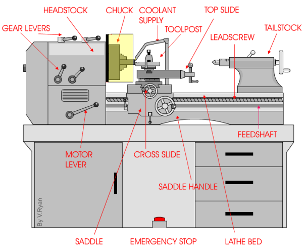
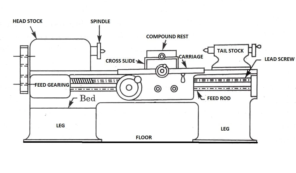
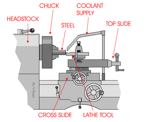
The Centre Lathe is used to manufacture cylindrical shapes from a range of materials including; steels and plastics. Many of the components that go together to make an engine work have been manufactured using lathes. These may be lathes operated directly by people (manual lathes) or computer controlled lathes (CNC machines) that have been programmed to carry out a particular task. A basic manual centre lathe is shown below. This type of lathe is controlled by a person turning the various handles on the top slide and cross slide in order to make a product / part.
The headstock of a centre lathe can be opened, revealing an arrangement of gears. These gears are sometimes replaced to alter the speed of rotation of the chuck. The lathe must be switched off before opening, although the motor should automatically cut off if the door is opened while the machine is running (a safety feature).
The speed of rotation of the chuck is usually set by using the gear levers. These are usually on top of the headstock or along the front and allow for a wide range of speeds.
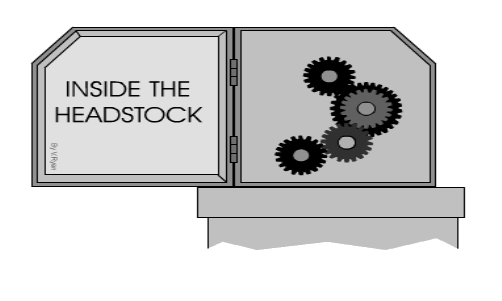
However, sometimes the only way to set the lathe to a particular speed is to change the gear arrangement inside the headstock. Most machines will have a number of alterative gear wheels for this purpose.
i) Basic element:
A lathe machine tool consists of several parts like:
- Headstock
- Bed
- Tailstock
- Carriage
- Saddle
- Cross-slide
- Compound rest
- Tool post
- Apron
- Lead Screw
- Feed rod
- Chuck
- Main spindle
- Leg
1) Head Stock:
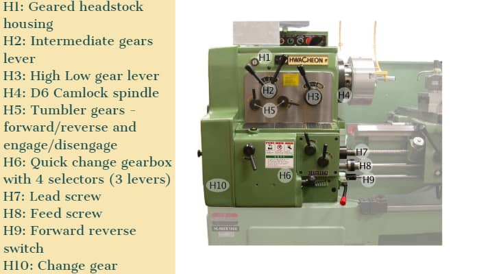
Head Stock is situated at the left side of the lathe bed and it is the house of the driving mechanism and electrical mechanism of a Lathe machine tool.
- It holds the job on its spindle nose having external screw threads and internally Morse taper for holding lathe center. And it is rotating at a different speed by cone pulley or all geared drive. There is a hole throughout spindle for handling long bar work.
- Head Stock transmits power from the spindle to the feed rod, lead screw and thread cutting mechanism.
Accessories mounted on headstock spindle:
- Three jaw chuck
- Four jaw chuck
- Lathe center and lathe dog
- Collect chuck
- Faceplate
- Magnetic chuck
A separate speed change gearbox is placed below headstock to reduce the speed in order to have different feed rates for threading and automatic lateral movement of the carriage. The feed rod is used for most turning operation and the lead screw is used for thread cutting operation.
2) Bed:
It is the base of the lathe machine. It is made of single piece casting of Semi-steel (Chilled Cast Iron). The bed consists of two heavy metal slides running lengthwise, with ways or ‘V’ formed upon them and rigidly supported with cross girths.
- It is sufficiently rigid and good damping capacity to absorb vibration.
- It prevents the deflection produced by the cutting forces.
- It supports the headstock, tailstock, carriage and other components of the lathe machine.
3) Tail Stock:
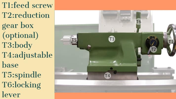
Tail Stock is situated on the right side above the lathe bed. It is used for:
- Support the long end of the job for holding and minimizes its sagging.
- It holds the tool for performing different operations like drilling, reaming, tapping, etc.
- And it is also used for a small amount of taper for a long job by offsetting the tailstock.
4) Carriage:
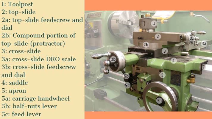
The carriage is used for support, guide and feed the tool against the job when the machining is done.
- It holds moves and controls the cutting tool.
- It gives rigid supports to the tool during operations.
- It transfers power from feed rod to cutting tool through apron mechanism for longitudinal cross-feeding.
- It simplifies the thread cutting operation with the help of lead screw and half nut mechanism.
It is consists of:
- Saddle
- Cross-slide
- Compound rest
- Tool post
- Apron
It provides three movements to the tool:
- Longitudinal feed-through carriage movement
- Cross feed-through cross slide movement
- Angular feed-through top slide movement
5) Saddle:
Generally, it is made up of ‘H’ shaped casting and it has a ‘V’ guide and a flat guide for mounting it on the lathe bed guide ways.
6) Cross-slide:
It is assembled on the top of the saddle. The top surface of the cross-slide is provided with T-slot.
7) Compound rest:
It supports the tool post and cutting tool in its various positions. It can be swiveled at any desired position in the horizontal plane. It is necessary for turning angles and boring short tapers.
8) Tool post:
It is the topmost portion of the carriage and it is used to hold various cutting tools or tool holders. There are three types of tool post commonly used and those are:
- Ring and rocker tool post
- Square head tool post
- Quick change tool post
9) Apron:
An apron is a house of the feed mechanism. It is fastened to the saddle and hangover in front of the bed.
10) Lead screw:
A lead screw is also known as a power screw or a translation screw. It converts rotational motion to linear motion. Lead Screw is used for Thread Cutting operation in a lathe machine tool.
11) Feed Rod:
Feed rod is used to move the carriage from the left side to the right side and also from the right side to the left side.
12) Chuck:
Chuck is used to holding the work piece securely.
There are generally 2 types of chucks:
- 3 jaw self-cantering chuck
- 4 jaw independent chuck
13) Main Spindle:
The spindle is a hollow cylindrical shaft in which long jobs can pass through it.
It is designed so well that the thrust of the cutting tool does not deflect the spindle.
14) Leg:
Legs are carrying an entire load of a lathe machine tool and transfer to the ground. The legs are firmly secured to the floor by the foundation bolt.
Ii) Working operation on lathe:
A Lathe Machine consists of the following operation:
1) Centering
2) Facing
3) Turning
4) Chamfering
5) Knurling
6) Thread cutting
7) Drilling
8) Boring
9) Reaming
10) Spinning
11) Tapping
12) Parting off
Before continuing any operation in lathe we have to load the job and center it on the head-stock spindle.
In lathe operations, the headstock spindle holds the job and it rotates with the same speed as the spindle. The carriage holding the tool on the tool post, also the carriage gives the tool post moves longitudinally or crosswise direction to give the desired feed on the job.
These two motions (longitudinally and crosswise) help to remove the chips of the metal and giving the proper shape of the job. The Lathe is such a versatile machine that it can produce another lathe. It is tough to mention which operations are not performed in a lathe machine tool, though we discuss some important lathe operations in detail.
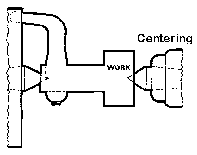
1) Centering operation in the lathe:
We use this operation for producing a conical hole in the face of the job to make the bearing support of the lathe center when the job is to hold between two canters. (Head-stock and Tail-stock)
 CENTERING OPERATION
2) Facing operation in the lathe:
Facing operation is for making the ends of the job to produce a smooth flat surface with the axis of operation or a certain length of a job. In this operation,
- Hold the job on Head-stock spindle using Three or four-jaw chuck.
- Start the machine on desire RPM to rotate the job.
- Give a desirable feed on the perpendicular direction of the axis of the job.
![22 Types of Lathe Machine Operations [Complete Guide] PDF](https://glossaread-contain.s3.ap-south-1.amazonaws.com/epub/1643283497_6886506.jpeg)
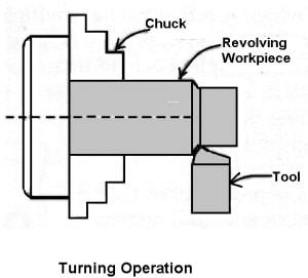
3) Turning operation in the lathe:
The operation by which we remove the excess material from the work piece to produce a cone shaped or a cylindrical surface
There are several types of turning operations, those are:
- Straight turning
- Shoulder turning
- Rough turning
- Finish turning
- Taper turning
- Eccentric turning
Straight turning:
This operation is done to produce a cylindrical surface by removing excess material from the work piece.
It is done in the following ways:
- Mount the job by suitable job holding device and check the trueness of the job axis with the lathe axis.
- Hold the cutting tool on the tool post and set the cutting edge at the job axis or slightly above it.
- Set the spindle as per the desired feed.
- Give depth of cut as per finish or rough cut.
- Start the machining.
- Engage automatic feed to move the carriage with the tool to the desired length, then disengage the feed and carriage is brought back to its starting.
- The process is repeated until the job finished.
STRAIGHT TURNING OPERATION
Shoulder turning:
A shoulder turning is called which has a different diameter to form a step from one diameter to another. There are four kinds of the shoulder.
- Square
- Bevelled
- Radius
- Undercut
![22 Types of Lathe Machine Operations [Complete Guide] PDF](https://glossaread-contain.s3.ap-south-1.amazonaws.com/epub/1643283497_8278139.jpeg)
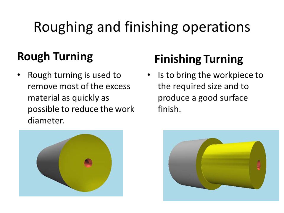
Rough turning:
It is a process of removal of excess material from the work piece in minimum time by applying a high rate of feed and heavy depth of cut.the depth of cut is around 2 to 5mm and the rate of feed is 0.3 to 1.5mm/revolution.
Finish turning:
The finish turning operation needs high cutting speed, minimum feed and a very small depth of cut to generate the smooth surface.
In finish turning the depth of cut is around 0.5 to 1mm and the rate of feed is 0.1 to 0.3 mm/revolution.
Taper turning:
A taper is defined as a uniform decrease or increase in the diameter of a work piece along with its length.
The operation by which a conical surface of the gradual reduction in diameter from a cylindrical work piece is produced is called taper turning.
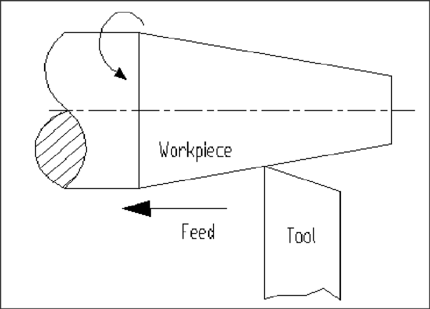
Taper turning methods:
A tapering form may be done by anyone of the following methods.
- Taper turning by form tool
- By swivelling the compound rest
- Tail-stock set over method
- By taper turning attachment
Let me discuss them in brief.
Taper turning by form tool:
It is used to form a short length of taper by using a form tool or broad nose tool.
Any increase in the length of taper will require the use of a wider cutting edge which may destroy the work piece due to the vibration and spoil the work piece. In this operation, the tool angle must be half of the taper angle.
Taper turning by swiveling the compound rest:
This method is used for turning step and short tapers.
It is done as follows:
- Set the compound rest by swiveling it from the centerline of the lathe center through an angle equal to a half taper angle.
- Clamp the carriage in place.
- After adjusting and setting the tool, feed is applied by the compound rest’s feed handle to complete the taper.
Tail-stock set over method:
Set over of tail-stock from its center-line is done equal to half taper.
Job is held between the centers. The length of the workpiece will be long enough. An only a small taper on a long job is done by this process.
It is used for external taper only.
By taper turning attachment:
It is done in the following ways:
- The cross slide is first made free from lead screw by hinder screw.
- The rear end of the cross slide is then tightened with a guide block by a belt.
- Set the guide bar at an angle to the lathe axis. (Half taper angle)
- The required depth of cut is given by the compound slide is at a right angle to the lathe axis.
4) Chamfering operation:
Chamfering is used for bevelling the end of a job to remove burrs, to look better, to make a passage of the nut into the bolt. This operation is done after thread cutting, knurling, rough turning.
![22 Types of Lathe Machine Operations [Complete Guide] PDF](https://glossaread-contain.s3.ap-south-1.amazonaws.com/epub/1643283498_0419405.jpeg)
5) Knurling operation:
It is the process of producing a rough surface on the workpiece to provide effective gripping. Knurling tool is held rigidly on the tool post and pressed against the rotating job so that leaving the exact facsimile of the tool on the surface of the job.
![22 Types of Lathe Machine Operations [Complete Guide] PDF](https://glossaread-contain.s3.ap-south-1.amazonaws.com/epub/1643283498_1021118.jpeg)
6) Thread cutting operation:
It is the operation that is used to produce a helical groove on a cylindrical or conical surface by feeding the tool longitudinally when the job revolved between the two canters.
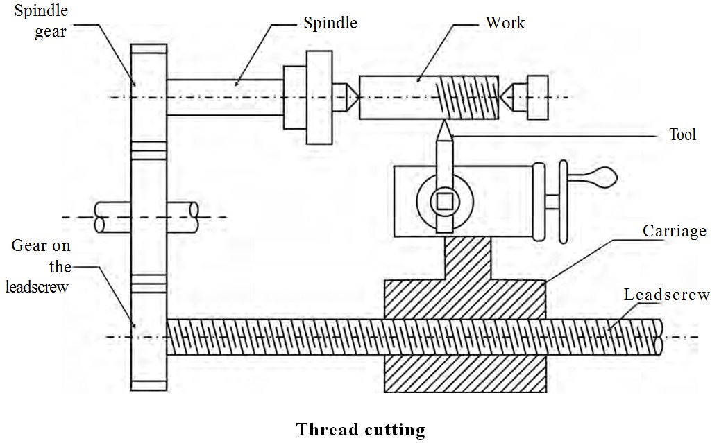
Tool setting for thread cutting operation:
The tool should be set exactly to the height of the center line of the job and at 90 degrees to the job.
Tool setting gauge is used for this purpose.
Feeding during thread cutting operation:
It is done in two ways.
- The tool may be feed exactly at 90 degrees to the job axis but it does not have good cutting action because only the front end of the tool does cutting.
- The tool may beefed at an angle from 27-30 degrees at which the compound rest may be set so that the complete side of the tool is used for cutting action which gives a better polish on the threads.
Job speed during threading:
The job speed will be 1/3 to 1/4th of the job speed in turning operation.
7) Drilling operation:
Drilling is an operation by which we can make holes in a job.
In this operation, the job is rotated at the turning speed on the lathe axis and the drilling tool fitted on the tail-stock spindle. And the tail-stock is moved towards the job by hand feed.
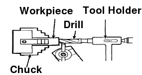
8) Boring operation:
In this operation, we can enlarge the diameter of the existing hole on a job by turning inside with some farm tool known as a boring tool. The boring tool is also fitted on tail-stock.
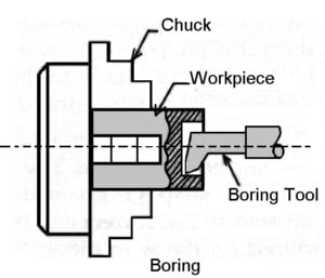
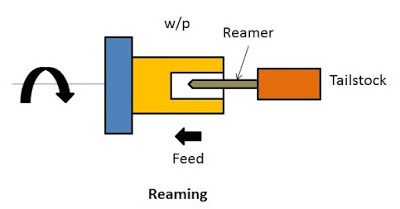
9) Reaming operation:
Reaming is the operation for sizing or finishing a drilled hole to the required size by a tool called reamer. This tool is fitted on tail-stock.
10) Spinning operation:
In this operation, the job of this sheet metal is held between the former and the tail-stock center rotates at high speed with the former.the long round nose forming tool rigidly fixed on special tool post presses the job on the periphery of the former. So the job is taken exactly the shape of the former. This is a chip less machining process.
11) Tapping operation:
We use this operation for creating internal threads within a hole by means of a tool called tap.
Three taps are generally used in an internal thread.
- Taper Tap
- Second Tap
- Plug Tap
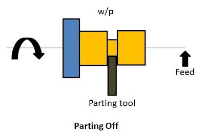
12) Parting-off operation:
It is the operation of cutting off a bar type job after complete the machining process. In this operation a bar type job is held on a chuck, rotates at turning speed, a parting off tool is fed into the job slowly until the tool reaches the center of the job.
Iv) Turning and facing:
Turning:
Turning a taper on a long piece of material is best achieved by offsetting the tailstock. The material is held between two centres as a normal three jaw chuck cannot be used. A three jaw chuck will not hold the material safely or accurately when a long taper is being turned. Diagram ‘A’ below shows the side view of the two centres, the material and the tool post. |
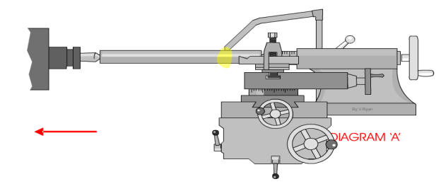 |
Diagram ‘B’ shows a bird’s eye view (plan view) of the same equipment. However, this time it can be seen that the tailstock has been adjusted so that it is off centre. This means that a long taper can be turned. A small amount of material must be removed with each pass of the cutting tool. Also the lathe should be setup so that the cutting tool feeds automatically along the bed of the lathe. This will lead to a better finish to the surface of the material. The animation below shows a 'speeded up version' of taper turning. Normally taper turning takes a long time. |
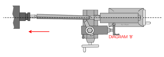 |
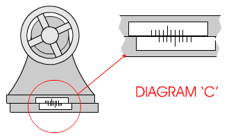
Diagram ‘C’ shows the scale at the back of the tailstock. To adjust the tailstock so that it is off centre usually means loosening a number of Allen screws, offsetting the tailstock and then tightening the screws back in position.
Facing:
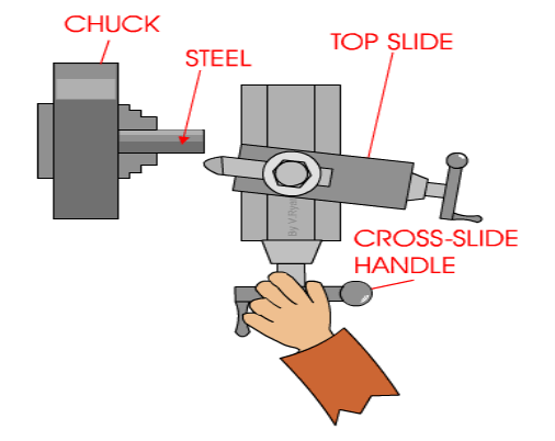
A very basic operation is called ‘facing off’. A piece of steel has been placed in the chuck and the lathe cutting tool is used to level the end. This is done by turning the cross-slide handle so that the cross-slide moves and the cutting tool cuts the surface of the steel. |
 |
Only a small amount of material should be removed - each pass of the cross slide. After each pass of the cutting tool the top slide can be rotated clockwise to move the tool forward approximately 1mm.
This sequence is repeated until the steel has been levelled (faced off).
When using a centre lathe it is always advisable to work patiently and safely. Do not attempt to remove too much material in one go. At best this will caused damage to the steel being worked on and to the expensive cutting tool being used. At worse an accident will occur.
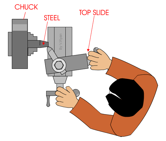
When turning a short taper the top slide is set a the required angle. This is normally done by loosening two small Allen screws and then rotating the topslide to the angle and tightening back up the two allen screws. |
 |
Horizontal milling machine – construction and working
Milling is the cutting operation that removes metal by feeding the work against a rotating, cutter having single or multiple cutting edges. Flat or curved surfaces of many shapes can be machined by milling with good finish and accuracy. A milling machine may also be used for drilling, slotting, making a circular profile and gear cutting by having suitable attachments.
Working Principle: The workpiece is holding on the worktable of the machine. The table movement controls the feed of workpiece against the rotating cutter. The cutter is mounted on a spindle or arbor and revolves at high speed. Except for rotation the cutter has no other motion. As the workpiece advances, the cutter teeth remove the metal from the surface of workpiece and the desired shape is produced.
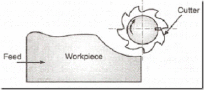
Horizontal Milling Machine Construction: The main part of machine is base, Column, Knee, Saddle, Table, Overarm, Arbor Support and Elevating Screw.
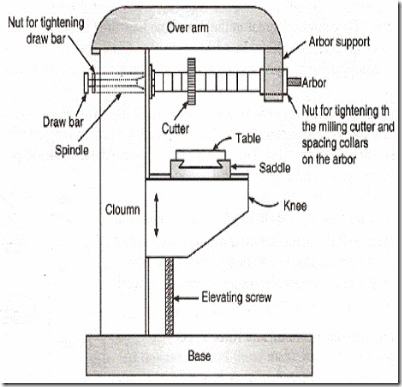
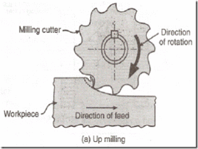
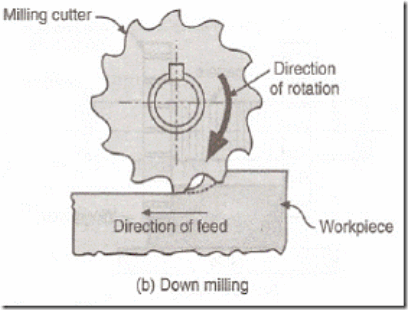
1. Base: It gives support and rigidity to the machine and also acts as a reservoir for the cutting fluids.
2. Column: The column is the main supporting frame mounted vertically on the base. The column is box shaped, heavily ribbed inside and houses all the driving mechanisms for the spindle and table feed
3. Knee: The knee is a rigid casting mounted on the front face of the column. The knee moves vertically along the guide ways and this movement enables to adjust the distance between the cutter and the job mounted on the table. The adjustment is obtained manually or automatically by operating the elevating screw provided below the knee.
4. Saddle: The saddle rests on the knee and constitutes the intermediate part between the knee and the table. The saddle moves transversely, i.e., crosswise (in or out) on guide ways provided on the knee.
5. Table: The table rests on guide ways in the saddle and provides support to the work. The table is made of cast iron, its top surface is accurately machined and carriers T-slots which accommodate the clamping bolt for fixing the work. The worktable and hence the job fitted on it is given motions in three directions:
a). Vertical (up and down) movement provided by raising or lowering the knee.
b). Cross (in or out) or transverse motion provided by moving the saddle in relation to knee.
c). Longitudinal (back and forth) motion provided by hand wheel fitted on the side of feed screw.
In addition to the above motions, the table of a universal milling machine can be swiveled 45° to either side of the centre line and thus fed at an angle to the spindle.
6. Overarm: The Overarm is mounted at the top of the column and is guided in perfect alignment by the machined surfaces. The Overarm is the support for the arbor.
7. Arbor support: The arbor support is fitted to the Overarm and can be clamped at any location on the Overarm. Its function is to align and support various arbors. The arbor is a machined shaft that holds and drives the cutters.
8. Elevating screw: The upward and downward movement to the knee and the table is given by the elevating screw that is operated by hand or an automatic feed.
Operations that can be performed in a Milling Machine:
There are several types of operation that can be performed in a milling machine, and those are:
- Plain Milling Operation
- Face Milling Operation
- End Milling Operation
- For Milling Operation
- T-slot Milling Operation
- Side Milling Operation
- Gear Milling Operation
- Straddle Milling Operation
- Grooves Milling Operation
- Gang Milling Operation
Horizontal milling machine – construction and working
Milling is the cutting operation that removes metal by feeding the work against a rotating, cutter having single or multiple cutting edges. Flat or curved surfaces of many shapes can be machined by milling with good finish and accuracy. A milling machine may also be used for drilling, slotting, making a circular profile and gear cutting by having suitable attachments.
Working Principle: The workpiece is holding on the worktable of the machine. The table movement controls the feed of workpiece against the rotating cutter. The cutter is mounted on a spindle or arbor and revolves at high speed. Except for rotation the cutter has no other motion. As the workpiece advances, the cutter teeth remove the metal from the surface of workpiece and the desired shape is produced.
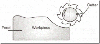
Horizontal Milling Machine Construction: The main part of machine is base, Column, Knee, Saddle, Table, Overarm, Arbor Support and Elevating Screw.
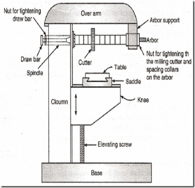
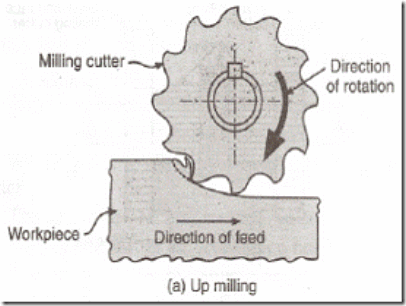
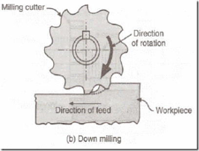
1. Base: It gives support and rigidity to the machine and also acts as a reservoir for the cutting fluids.
2. Column: The column is the main supporting frame mounted vertically on the base. The column is box shaped, heavily ribbed inside and houses all the driving mechanisms for the spindle and table feed
3. Knee: The knee is a rigid casting mounted on the front face of the column. The knee moves vertically along the guide ways and this movement enables to adjust the distance between the cutter and the job mounted on the table. The adjustment is obtained manually or automatically by operating the elevating screw provided below the knee.
4. Saddle: The saddle rests on the knee and constitutes the intermediate part between the knee and the table. The saddle moves transversely, i.e., crosswise (in or out) on guide ways provided on the knee.
5. Table: The table rests on guide ways in the saddle and provides support to the work. The table is made of cast iron, its top surface is accurately machined and carriers T-slots which accommodate the clamping bolt for fixing the work. The worktable and hence the job fitted on it is given motions in three directions:
a). Vertical (up and down) movement provided by raising or lowering the knee.
b). Cross (in or out) or transverse motion provided by moving the saddle in relation to knee.
c). Longitudinal (back and forth) motion provided by hand wheel fitted on the side of feed screw.
In addition to the above motions, the table of a universal milling machine can be swiveled 45° to either side of the centre line and thus fed at an angle to the spindle.
6. Overarm: The Overarm is mounted at the top of the column and is guided in perfect alignment by the machined surfaces. The Overarm is the support for the arbor.
7. Arbor support: The arbor support is fitted to the Overarm and can be clamped at any location on the Overarm. Its function is to align and support various arbors. The arbor is a machined shaft that holds and drives the cutters.
8. Elevating screw: The upward and downward movement to the knee and the table is given by the elevating screw that is operated by hand or an automatic feed.
Operations that can be performed in a Milling Machine:
There are several types of operation that can be performed in a milling machine, and those are:
- Plain Milling Operation
- Face Milling Operation
- End Milling Operation
- For Milling Operation
- T-slot Milling Operation
- Side Milling Operation
- Gear Milling Operation
- Straddle Milling Operation
- Grooves Milling Operation
- Gang Milling Operation
The advantages of the Milling machine:
In the milling machine there are following advantages, those are:
- Ideal for the production of individual pieces and small batches.
- Capable of producing complex shapes with the use of multitooth, as well as a single point, cutting tools.
- Operation cost can be very modest given general-purpose equipment and cutters are used.
Milling Machine Disadvantages:
These are the following disadvantages of a milling machine:
- It is more costly than casting, cold forming, extrusion, etc. If these processes can provide the flatness, surface finish and dimensional accuracy required for the part.
- For mass production, it becomes economically necessary to use special-purpose machines.
- They may cost millions of dollars but the cost is justifiable when handling labour which is virtually eliminated and machining accuracy and repeatability is ensured.
The applications of Milling Machine:
These are the following applications of the milling machine:
- This machines used to making gears.
- Usually used to a machined flat surface but can also produce irregular surfaces.
- Used to produce the groove or slot.
- Modern mill machine cut super alloys, titanium, tensile steel to closer tolerance, a greater accuracy, and faster rate.
- This machine is used to design of metal and other materials.
Shaper machine
The Shaper Machine is a reciprocating type of machine tool basically used to produce Horizontal, Vertical or Inclined flat surfaces by means of straight-line reciprocating single-point cutting tools similar to those which is used in lathe operation.
Working Principle of Shaper Machine:
A shaper machine is working on the following principle:
- A shaper machine holds the Single point cutting tool in ram and workpiece is fixed over the table.
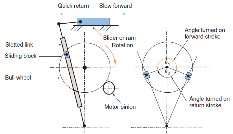
- The ram holding the tool reciprocates over the workpiece and metal is cut during the forward stroke called a cutting stroke and
- No metal is cut during its return stroke is called an Idle stroke.
- The feed is given at the end of the cutting stroke.
- Generally, the cutting stroke is carried out at slow speed and the idle stroke is carried at high speed with the help of quick return mechanism.
In the shaper machine, there is another mechanism called Quick return Motion Mechanism.
In the forward stroke, the Slider moves fast and removing the material from the workpiece.
Whereas in the return stroke, the Slider moves faster than the forward stroke that means Quick return, it takes less time to return, called a return stroke.
Types of Shaper Machine:
Based on the type of driving mechanism types of shaper machines.
- Crank type (Example: Quick return Motion Mechanism)
- Geared type shaper
- Hydraulic type (I mentioned the working principle of hydraulic shaper machine below in this article)
Based on ram travel types of shaper machines.
- Horizontal Shaper
- Vertical Shaper
Based on the table design types of shaper machines.
- Standard or Plain Shaper
- Universal shaper
Standard or Plain Shaper:
In this machine, the table has only two motion: crosswise in the horizontal plane and vertical movement (up and down).
The table is not provided with a swiveling motion.
Universal shaper:
This machine is similar to plain shaper except that the table can be tilted at a various angle, making it possible to inclined flat surfaces.
The table can be swiveled about 360 degrees about a central axis parallel to the cutting stroke direction and also perpendicular to it, that is, around two horizontal axes.
The table also has a movement in the horizontal plane and vertical direction (up and down ) as in plain shaper.
There are 4-types of operations performed in a shaper machine, and those are:
- Horizontal cutting
- Vertical cutting
- Inclined cutting
- Irregular cutting
Advantages of Shaper Machine:
- The single point tool used is inexpensive or we can say low tooling cost.
- The cutting stroke having a definite stopping point.
- The work can be held easily in the shaper machine.
- The set up is very quick and easy and also can be readily changed from one job to another job.
Disadvantages of Shaper Machine:
- By nature, it is a slow machine because of its straight-line forward and returns strokes the single point cutting tool requires Several strokes to complete a work. (They are slow)
- The cutting speed is not usually very high speeds of reciprocating motion due to high inertia force developed in the motion of the units and components of the machine.
Applications of Shaper Machine:
- To generate straight and flat surfaces.
- Smooth rough surfaces.
- Make internal splines.
- Make gear teeth.
- To make dovetail slides.
- Make key ways in pullies or gears.
- Machining of die, punches, straight and curved slots.
Slip gauges were first developed by Johnson, and sometimes also called as ‘Johnson Gauge Blocks’. These are rectangular blocks of steel having a cross-section of about 32 mm x 9 mm.
Slip gauges are the universally accepted ‘standard of length’ in industries. These are the simplest possible means of measuring linear dimensions very accurately.
Need of Slip Gauges:
For tool-room and other precision work, the ordinary methods of measurement are not always accurate. Micrometer and verniers calliper can be used to check tolerance fine within 0.002 to 0.02 mm, but for fine tolerance they are not effective. Thus there is a need of instrument which can measure fine tolerance limit.
The means to do so are ‘slip gauges’. They can be used to measure tolerances in the range of 0.001 to 0.0005 mm very accurately.
Grades of Accuracy of Slip Gauges:
Slip gauges are made in five grades of accuracy. Calibration grade, grade 00, grade 0, grade I, and grade II, in the decreasing order of accuracy.
Grade 0, grade I, grade II are used for general workshop purpose and are known as working gauge blocks, whereas, calibration grade (master gauge blocks) and grade 00 (Inspection gauge blocks) are used only for checking other types of blocks.
(i) Calibration Grade:
This is special grade and is used for experimental work, research work and for measurement and inspection of other gauges (grades).
(ii) Grade 00:
This is also termed as inspection gauge block. This is used for highest precision work such as measuring Grade I and II.
(iii) Grade 0:
This is used for tool room or machine shop inspection.
(iv) Grade I:
This is used for more precise work such as setting up sine bars, checking gap gauges, measurement of components, tools etc.
(v) Grade II:
This is used in workshop for rough checks, for ordinary inspection work, for setting up machine tools, and for measurement where production tolerances are relatively wide.
Slip Gauges Sets:
Gauge blocks are available in sets with steps with steps of 10, 1, 0.1, 0.01 and 0.001 mm. On small size blocks, the size is marked on the measuring face, and large blocks are marked on a side surface.
The sets are available in ‘Metric’ and ‘English’ units. Letter ‘E’ is used for inch units (English units) and Letter “M’ is used for mm units (Metric units). The number of pieces in a set is given by the number followed by letter E or M. For Example, E 81 refers to a set whose blocks are in inch unit and 81 in number. Similarly M 45 refers to a set whose blocks are in mm units and are 45 in number.
Accuracy of Gauge Blocks:
The accuracy of gauge blokes is affected by temperature changes. They are accurate within a temperature of 20°C and humidity controlled atmosphere. Their accuracy should be checked time-to-time against any warn out or deformation in the blocks. To do so, in industries, a set of gauge blocks are available as a reference set, to check the other working sets.
Manufacturing of Slip Gauges:
(Material) Most of the slip gauges are produced from high grade steel, hardened and stabilized by heat treatment process to give a high degree of dimensional stability. Slip gauges can be made from tool steel, chrome plate steel. Stainless steel, chrome carbide, tungsten carbide etc. Tungsten carbide is an extremely hard, wear resistant, and most expensive material than steel. Sometimes chrome plating is also used to improves the corrosion resistance.
Addition of chrome plates leads to the tendency of Flake-off, especially at the edges. Hence they are disliked by experienced workers.
(Method) Following steps gives a brief of method of manufacturing of slip gauges:
1. The high grade steel gauge blanks are taken with appropriate size.
2. They are subjected to hardened and rough grinding process.
3. Then they are subjected to a cyclic low temperature heat treatment, to provide stability of dimensions and to relieve the internal stress.
4. A batch of 8 blanks of similar nominal size is mounted on eight Co-planner Faces of a magnetic chuck.
5. Their one set of Faces is lapped truly flat by lapping process.
6. By changing the lapped faces on magnetic chuck, opposite Faces also lapped truly flat.
7. Now, the required Parallelism and equality of size is achieved by interchanging four of the eight gauges as shown in figure 1.8 (e). They are interchanged diagonally and turned end for end. Thus any errors in Parallelism are equalized.
8. Now, to determine whether the gauges are the required size they are removed from the chuck, wrong together in combination, and their aggregate size compared with an appropriate size master in a suitable comparator. A magnification of 8 is obtained in this calibration since, as each of the 8 gauges must be identical in size, the difference between combination and master may be divided by eight and this difference is distributed to each gauge.
9. If necessary, individual block can be mounted on chuck to bring their individual lengths within required accuracy.
Uses of Slip Gauges:
Slip gauges are important means of measurement in industries and laboratories.
Their uses are:
1. They universally accepted as a “Standard of length”.
2. They used for direct precise measurement where accuracy of work piece being measure is high.
3. They used with high-magnification comparators, to establish the size of the gauge blocks.
4. They are used for checking the accuracy of measuring instruments.
5. They are used to setting up a comparator to specific dimension.
6. They are used to check a batch of components quickly and accurately.
Care of Slip Gauges:
Since the initial cost of slip gauges in high, so to maintain their accuracy, they require great care.
Following points should be kept in mind regarding the care of slip gauges:
1. When not in use, the slip gauges should be kept in their respective positions in the gauge box.
2. Before wringing the blocks together, ensure that their faces are perfectly clean.
3. Measuring faces should not be fingered.
4. Gauges should not be wrong together over an open gauge box, due to the possibility of accidently drop of any gauge on several gauges placed in the box and could be damaged.
5. Gauges should not be wrung together for a long time.
6. After use, does not break the pile but slide one gauge over the other to separate them.
7. After use, a thin layer of good quality grease should be applied on their faces, before they are kept in their case.
8. As far as possible, slip gauges should be used in air-conditioned rooms, free from dust and maintained constant temperature.
9. During the use, their working faces should never be placed on the surface plate etc.
10. Check accuracy at appropriate intervals.
11. Use minimum number of gauges for a combination.
12. Wring together in correct manner.
13. Use 2.5mm protector slips whenever possible.
Go - No Go gauges are manual mechanical measuring tools used in production lines to guarantee the machining has taken place and it has been performed correctly.
They differ from each other based on the type of surface check being performed; for example geometry and/or dimension. There are two types:
- Plug-shaped for internal round holes
- Fork-shaped for external diameters, ring-shaped for external cylindrical holes, with particular shapes for special gauges
They are shaped specifically so the GO gauge passes in the machined area, whilst the NO GO gauge does not.
The most frequently checked parameters are:
- Geometries / Dimensions and depth of the holes
- Geometries / Outside diameters (shafts)
- Length and thickness
- External and internal threads
- Holes and grooved shafts
- Chamfer
- Radius
- Angle
Benefits of Go/No Go Gages
Go and No Go Gages are typically simple devices like Go and No Go plug gages, Go and No Go ring gages or Go and No Go Snap Gages that contain no moving parts and are easy to use. As such, their use is very common. Go and No go gages are also easily portable, do not suffer breakdowns in service, and typically do not require power.
Because Go and No Go gages are available in an extensive range of sizes and tolerances and offer increased assurance of a fit between mating parts, it is easy to see why these types of gages are the most widely used in inspection.
Setting Gages and Fixed Limit Gages
The gaging practice known as “Go and No Go Gaging,” is often used with ring, plugs, and snap gages. They are utilized as a full form or three dimensional simulation of the mating part.
Go/No Go Gauges Inspection Practice
In this gaging practice, a Go Gage is used, serving as the equivalent to one of the part's specified features. If the Go Gage fits into the part, then it stands to reason that the mating part does not have excessive material and will also fit, ensuring proper assembly. Likewise, if the No Go Gage does not fit into the part, it shows that the feature under inspection is not lacking material or is not too large and consequently too loose.
The Go No Go Gauge practice is a quick, efficient, and cost-effective verification that part dimensions meet drawing requirements and will assemble and function properly.
Using Plain Plug Go/No Go Gages
Plain plug gages are available in many different types and are utilized for a variety of inspections. Reversible wire plug gages are held in a collet-type handle that forms either a single-end or double-end Go, No Go Gauge Assembly. Reversible wire plug gages are available in a range from .004"-1.000", and in a tolerance range from class Z-XXX. Go and No Go Gauges are utilized for checking hole sizes. Wire type reversible plug gages also referred to as pin gages have become very popular, due to their low cost and availability in thousands of sizes.
To inspect hole size of a part, the Go gage is inserted into the hole. If the gage can be entered into the hole, then the hole is considered to be above its low limit. Following that, the No Go gauge is used: if it enters the hole, than the hole is too big.
Using a series of plugs in various diameter steps will result in a high repeatability rate. Gaging should be performed under optimal conditions so as to have little effect upon the inspection, such as cleanliness of the part and proper temperature control. Work tolerance might also be a factor to consider, in which a gage wear allowance may be used. In this case, a wear allowance is added to the Go Gage diameter. A tolerance should be specified so that the total gage tolerance does not exceed 10% of the part tolerance.
For very fine tolerances, a carbide plus gage is often the most effective and practical gage to be utilized. Additionally, many gage users also elect to use Go and No Go plugs in addition to air gaging or electronic inspections, in order to ensure that the parts will mate.
Using Plain Ring Go/No Go Gauges
Go and No Go ring gages are commonly used limit measurements on cylindrical outside diameters. Go and No Go ring gages are typically made from hardened tool steel. They can also be made with a chrome coat or with a carbide insert for greater wear resistance. Go and No Go ring gages are made to exacting gage maker tolerances. The Go and No Go gaging principles that are used for plug gages are applied to ring gages as well.
Dial gauges are measuring instruments that can accurately measure minute lengths and displacements. Unlike other measuring instruments that directly measure numerical values, they are used for measuring the difference compared to a reference or correcting parallelism. Dial gauges are available in various types, including a standard type and lever type. The standard type uses gears and a lever to convert the linear motion of a spindle into rotational motion, mechanically expand this motion and indicate the displacement with a scale. They are suited to observing significant changes. The lever-type uses sector gears and crown gears to expand the motion. While the lever-type has a higher resolution than the standard type, the variation is converted into the rotational motion of the lever, so a big change may be indicated with a smaller figure than the actual number. A single reading of a standard-type dial gauge is 0.01 mm, but there are also special dial gauges with a single reading of 0.001 mm. In addition to an analog type where measurements are read on a scale, a digital type is available as well.
Vernier caliper, instrument for making very accurate linear measurements introduced in 1631 by Pierre Vernier of France. It utilizes two graduated scales: a main scale similar to that on a ruler and an especially graduated auxiliary scale, the Vernier that slides parallel to the main scale and enables readings to be made to a fraction of a division on the main scale. Vernier calipers are widely used in scientific laboratories and in manufacturing for quality control measurements.
A quick guide on how to read a vernier caliper. A vernier caliper outputs measurement readings in centimetres (cm) and it is precise up to 2 decimal places (E.g. 1.23 cm).
Note: The measurement-reading technique described in this post will be similar for vernier calipers which output measurement readings in inches.
Measurement Reading Technique For Vernier Caliper
In order to read the measurement readings from vernier caliper properly, you need to remember two things before we start. For example, if a vernier caliper output a measurement reading of 2.13 cm, this means that:
- The main scale contributes the main number(s) and one decimal place to the reading (E.g. 2.1 cm, whereby 2 is the main number and 0.1 is the one decimal place number)
- The vernier scale contributes the second decimal place to the reading (E.g. 0.03 cm)
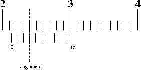
Let’s examine the image of the vernier caliper readings above. We will just use a two steps method to get the measurement reading from this:
- To obtain the main scale reading: Look at the image above, 2.1 cm is to the immediate left of the zero on the vernier scale. Hence, the main scale reading is 2.1 cm
- To obtain the vernier scale reading: Look at the image above and look closely for an alignment of the scale lines of the main scale and vernier scale. In the image above, the aligned line correspond to 3. Hence, the vernier scale reading is 0.03 cm.
In order to obtain the final measurement reading, we will add the main scale reading and vernier scale reading together. This will give 2.1 cm + 0.03 cm = 2.13 cm.
In a nutshell
Use the following formula:
Obtained reading=Main scale reading+Vernier scale readingObtained reading=Main scale reading+Vernier scale reading
Let’s go through another example to ensure that you understand the above steps:
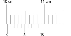
Main scale reading: 10.0 cm (Immediate left of zero)
Vernier scale reading: 0.02 cm (Alignment of scale lines)
Measurement reading: 10.02 cm
Compensating For Zero Error
In a nutshell
Use the following formula:
Correct reading=Obtained reading–Zero error Correct reading=Obtained reading–Zero error
Where zero error zero error can be either negative (the “0” of vernier scale is left of the “0” of the main scale) or positive (the “0” of vernier scale is right of the “0” of the main scale)
Explanation
Now, we shall try with zero error. If you are not familiar on how to handle zero error for vernier calipers, I suggest that you read up on Measurement of Length.
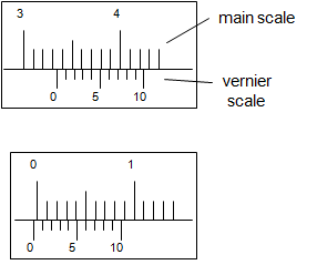
The reading on the top is the measurement obtained and the reading at the bottom is the zero error. Find the actual measurement. (Meaning: get rid of the zero error in the measurement or take into account the zero error)
Measurement with zero error: 3.34 cm
Zero error: – 0.04 cm (negative because the Vernier scale is to the left)
Measurement without zero error: 3.34–(–0.04)=3.383.34–(–0.04)=3.38 cm
Micrometer, in full micrometer caliper, instrument for making precise linear measurements of dimensions such as diameters, thicknesses, and lengths of solid bodies; it consists of a C-shaped frame with a movable jaw operated by an integral screw. The fineness of the measurement that can be made depends on the lead of the screw—i.e., the amount the spindle moves toward or away from the anvil in one revolution and the means provided for indicating fractional parts of a revolution. The accuracy of the measurements depends on the accuracy of the screw-nut combination.
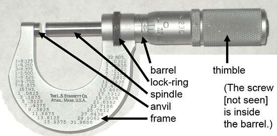
Micrometer
The sine bar is the most accurate instrument for measuring angles. It consists of a accurate straight rectangular bar made of high quality steel and having two accurately lapped cylindrical plugs or rollers at the ends.
Sine bar is specified by the distance between the centres of two rollers i.e., 100mm, 200mm, 250mm, or 300mm, two rollers must be of same diameters. The various parts of sine bar are hardened before grinding and lapping.
The rollers are so fixed that when sine bar is placed on surface plate, the surface of the bar is exactly parallel to surface plate.
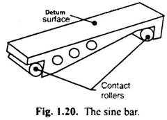
Types of Available Sine Bars:
Sine bars are available in different forms and sizes, according to the purpose of its use and method of application. In design (a), the plugs project about 12 mm from the front face of the bar and in design (b) and (c), the ends of the bar are stepped and the plugs are secured into each step by screw. Different available types of sine bar are shown in fig. 1.21. Sine bar is also available in inches.
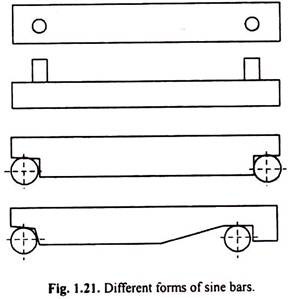
Principle of Working of Sine Bar:
The principle of operation of the sine bar is based upon the application of trigonometry. In a right angle triangle ABC shown in Fig. 1.22, the ratio of the length BC (perpendicular) to that of the length AB (hypotenuse) is referred to as the sine of the angle θ

The ratio will always be the same irrespective of the length of sides of the triangle. By placing the slip gauges under the one roller, the bar surface can be made parallel to any angular surface of work.
Then by measuring the total height made by slip gauge, the angle can be found by using the formula:

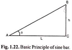
Where, h = height made by slip gauge.
L = distance a between the centres of rollers.
Measurement of Angle for Small Component:
For checking the angle of small size components, a sine bar is set up approximate (Nominal) angle on a surface plate by suitable combination of slip gauges.
The component being checked is placed over the surface of a sine bar as shown in Fig. 1.23. A dial gauge is mounted upon a suitable stand such as universal surface gauge.
It is moved over the component throughout its length. If there is a variation in parallelism of the upper surface of the component and the surface plate, it is indicated by the deflection of pointer.
Now, we tried to adjust the slip gauges height so that the dial indicator reads zero position.
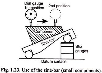
Then in this situation, the angle of the component is given by:

Where, θ = is the angel to be measure
h = height of the slip gauges.
L = Length of the sine bar (between centres)
Measurement of Angle for Large Component:
When component is too large to be mounted on the sin-bar, the sine bar can be mounted on the component as shown in figure 1.24.
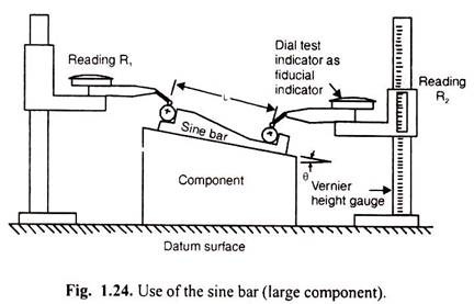
The height over the rollers is measured by means of a vernier height gauge. A dial gauge is also used to check the measuring pressure. Now, adjusting the height gauge until the dial gauge reads zero reading each time. The difference of the two height gauge reading being the rise of the sine-bar as shown in fig 1.24
The angle of the component is given by:

Uses of Sine Bar:
A sine bar has to be used in conjunction with a surface plate and slip gauges. Sine bar is used for checking angle of components, taper of work pieces, etc. It is also used for setting a work to a known required angle.
Height gauges consist of a sliding carriage with a moving stylus or scribe that is mounted to a vertical axis beam or column that contains a measuring scale. The beam is configured so that it is perpendicular to the base of the height gauge, which is typically made using a rigid material to add stability to the instrument for measurements. The beam or column height can vary from 6 inches or less to upwards of 6 feet, depending on the model. Custom gauges may extend the column height even higher. The carriage movement is controllable and may be adjusted by a set of adjustment screws for coarse or fine adjustments and may be locked into position as needed. A measuring jaw is used whose upper and lower surfaces are parallel to the base of the height gauge. In the case where it is desired to scribe the workpiece, a specialized scribing attachment can be used in place of the measuring jaw.
When using a height gauge, a granite surface plate is typically used to measure and scribe part features from a datum plane. A touch probe, scriber, or other measuring probe is employed to locate the desired feature or point on the workpiece being inspected for measurement. Before performing measurements, care must be taken to assure that the gauge is properly seated on the surface and that there is no contamination that might interfere with accurate measurements. Height gauge manufacturers will typically recommend that the bottom of the height gauge be inspected prior to its use. An abrasive, such as a rubber stone or cera stone, should be employed to remove scratches, burrs, or other surface imperfections that may impact the readings. The use of a mild cleaning solvent such as denatured alcohol is also recommended to remove any material that has accumulated from the use of the stones.
Once the height gauge base and surface plate have been properly cleaned, the instrument should be zeroed out by using a test probe brought to the surface that will be used as the reference plane or reference point. Test the surface while pressing down on the corners of the part. Any variation in the reading on the indicator reflects that the surface level is not correct, and the stoning and cleaning steps need to be repeated to correct the condition. The use of gage blocks is also recommended to validate all dimensional readings taken by a height gauge.
Types of height gauges
Height gauges may be broadly characterized into four basic types:
- Vernier height gauges
- Dial height gauges
- Digital counter height gauges
- Electronic height gauges
Vernier height gauges
Vernier height gauges employ the use of a main scale and a Vernier scale to provide for greater resolution of the measured value. They are generally available in measuring size ranges from 6 inches to 6 feet. Models can have imperial (inch) or metric (mm) scales or both on them.
Dial height gauges
Dial height gauges tend to be available in smaller measuring size ranges, typically less than 12 inches or 300 mm. These units feature a mechanical dial with a needle pointer that allows for easy reading. Because of their size, dial height gauges are very portable and can be stored in a toolbox.
Digital counter height gauges
Digital counter height gauges combine a dial and needle as found on the dial height gauge type with a dual-digit counter to increase the speed and efficiency of the measurement process. The counter will allow readings to tenths of an inch while thousandths of an inch can be read on the dial. The presence of an additional counter also has the advantage in that it enables users to set and maintain an absolute and floating zero if needed.
Electronic height gauges
Sometimes called digital height gauges (not to be confused with digital counter height gauges), electronic height gauges substitute digital displays for the analog dials and mechanical counters found on the other types of gauges. Electronic height gauges generally allow the user to select from different units of measure such as inches versus millimeters. Higher-end models also add a host of additional features and capabilities that improve the measuring capabilities and accuracy. Examples of some of these capabilities include:
- An air bearing or air cushion system that allows for light and smooth movement of the gauge
- A motorized measuring carriage that simplifies the measurement process and eliminates the need for the operator to move the carriage
- Built-in temperature compensation capabilities to allow for the variation in coefficients of thermal expansion across material types being measured
- Data storage and output capabilities, allowing for use with SPC software applications by outputting data through RS323 or USB bus
The capabilities help to automate the measurement process, making measurements less depending upon the operator's skill and allowing for greater throughput in a production setting.
Height gauge sizes and specifications
Height gauges are typically sized and specified by several common parameters which are shown below. Note that the specifications for these devices may vary from manufacturer to manufacturer and note as well that the specifications can be different depending on the type of height gauge. Having a basic understanding of these specifications will make the process of sourcing or specifying a model easier to accomplish.
- Measuring range/size – represents the vertical range over which the height gauge can provide measurements.
- Graduation – reflects the number of lines that appear on the measurement scale for the device. More lines allow for more granularity of measurement.
- Accuracy – a measure of the degree to which the measured value of height as reported by the gauge deviates from the actual value. Accuracy is sometimes defined as a +/- percentage of the full-scale value of the gauge or as an absolute value in length units. Generally, the gauge accuracy will depend on the measuring range and units with higher measuring range will show greater variations (+/- accuracy specification).
- Resolution – reflects the least significant digit of the measured value that can be obtained using the instrument. For digital height gauges, the number of digits in the display usually reflects the instrument’s resolution.
- Repeatability – also called precision, is a measure of the gauge’s ability to generate the same reading for a measured dimension on a given part when that measurement is performed many times. If a gauge has poor repeatability, then each measurement taken will yield a different result.
- Measuring force – the value of the force applied to the test workpiece by the gauge measuring probe or jaw.
- Maximum measurement speed – for motorized height gauges, indicates the maximum rate of travel for the carriage as it moves along the beam, measured in units of length/time such as mm/s.
- Perpendicularity – a specification that defines the deviation from pure 90o positioning of the height gauge beam to the surface plate or base.
- Display type – for electronic height gauges, describes the type of display option available, such as LCD, LED, or high-resolution color display.
- Probe/carrier options – depending on the model and gauge type, a variety of different measurement probes and carriers may be available to use for performing specialized measurements against holes, slots, angles, and other part features. These can include disc probes, cylindrical probes, taper probes, depth probes, and spherical probes, transducers for checking of perpendicularity, and measuring crooks, to name a few.
Uses of height gauges
Height gauges are used in quality control applications and can perform several types of measurements:
- To measure the distance from a reference surface to a specific feature of a part to verify that it meets specifications and tolerances
- To scribe a part with accurate vertical dimensions or features from a datum plane so that additional machining can be done
- To perform 2D measurements of part features
- To verify center-to-center dimensions
- To measure flatness
- To measure angles
- To measure straightness/squareness or perpendicularity of parts