UNIT 1
D.C. Circuits
The three essential elements in circuit analysis:
• Resistance R
• Capacitance C
• Inductance L
Their V and I relationships are summarized below
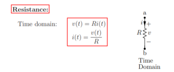
Resistance is a static element in the sense v(t) versus i(t) relationship is instantaneous. For example, v(t) at time t = 2 seconds simply depends only on i(t) at t = 2 seconds and nothing else. This implies that the resistance does not know what happened in the past, in other words it does not store any energy unlike other elements C and L.
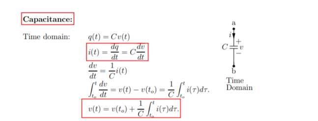
Capacitance: Time domain:
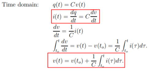
q(t) = Cv(t)
i(t) = dq /dt = C dv/ dt
Dv/dt = 1/C i(t)
 = v(t) – v(to) = 1/C
  d
d 
For a capacitance the v(t) versus i(t) relationship and vice versa at any time t depends on the past as they involve differentials and integrals. This implies that the capacitance is a dynamic element.
Inductance:

Time domain v(t) = L di/dt
Di/dt = 1/L v(t)
 = i(t) – i(to) = 1/L
  d τ
d τ
i(t) = i(to) + 1/L  dτ
dτ
Ideal and practical Voltage and Current source:
A voltage source is a device which provides a constant voltage to load at any instance of time and is independent of the current drawn from it. This type of source is known as an ideal voltage source. Practically, the ideal voltage source cannot be made. It has zero internal resistance. It is denoted by this symbol.
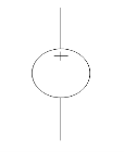
Fig: Voltage source symbol
Ideal Voltage Source
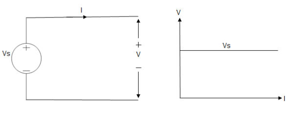
Fig: Ideal Voltage Source
The graph represents the change in voltage of the voltage source with respect to time. It is constant at any instance of time.
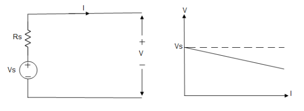
Voltage sources that have some amount of internal resistance are known as a practical voltage source. Due to this internal resistance, voltage drop takes place. If the internal resistance is high, less voltage will be provided to load and if the internal resistance is less, the voltage source will be closer to an ideal voltage source. A practical voltage source is thus denoted by a resistance in series which represents the internal resistance of source.
Practical Voltage source
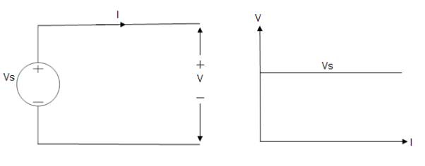
Fig: Practical Voltage source
The graph represents the voltage of the voltage source with respect to time. It is not constant but it keeps on decreasing as the time passes.
Current source
A current source is a device which provides the constant current to load at any time and is independent of the voltage supplied to the circuit. This type of current is known as an ideal current source; practically ideal current source is also not available. It has infinite resistance. It is denoted by this symbol.
Ideal Current source
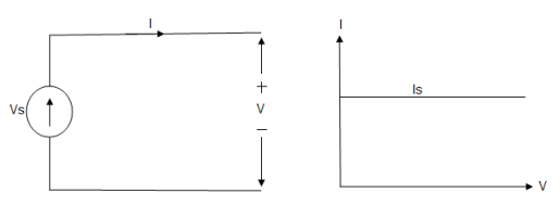
Fig: Ideal Current source
The graph represents the change in current of the current source with respect to time. It is constant at any instance of time.
Why ideal Current source has infinite resistance?
A current source is used to power a load, so that load will turn on. We try to supply 100% of the power to load. For that, we connect some resistance to transfer 100% of power to load because the current always takes the path of least resistance. So, in order for current to go to the path of least resistance, we must connect resistance higher than load. This is why we have the ideal current source to have infinite internal resistance. This infinite resistance will not affect voltage sources in the circuit.
Practical Current source
Practically current sources do not have infinite resistance across there but they have a finite internal resistance. So the current delivered by the practical current source is not constant and it is also dependent somewhat on the voltage across it.
A practical current source is represented as an ideal current source connected with resistance in parallel.
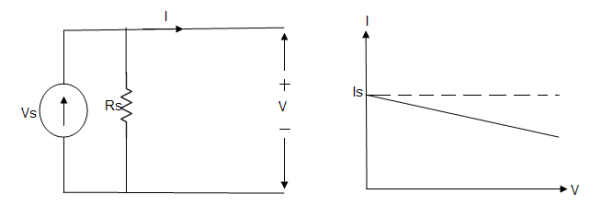
Fig; Practical Current source
The graph represents the current of the current source with respect to time. It is not constant but it also keeps on decreasing as the time passes.
Examples of current and voltage sources
The examples of current source are solar cells, transistors and examples of some voltage sources are batteries and alternators.
This was all about ideal and practical sources of power. The ideal sources are very useful for calculations in theory but as ideal sources are not practically possible, only practical sources are used in practical circuits. The batteries we use are a practical source of power and the voltage and current decreases as we use it. Thus both are useful to us in their own ways.
Superposition Theorem
- This is only applicable to circuits with linear elements.
- If two or more than two independent sources (voltage or current) are operating in the circuit than voltage across any element or current through any element is sum of current and voltages due to individual sources.
Question 1. Find the current through  resistance.
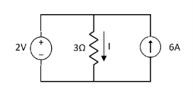
Solution:
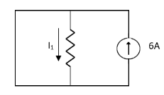
 1= 0
1= 0
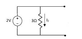
 2=
2=
 1 +
1 +  2
2 
Special Case:
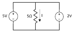
Since two voltage sources with different magnitude in parallel which cannot be connected as in single branch two different current is not possible (if 5V than I = zero).
Question:
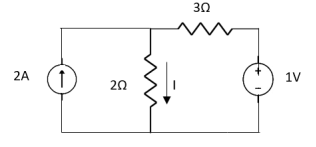
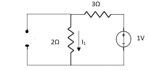
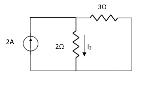
 1 =
1 = 
 2 =
2 = 
=
 1 +
1 +  2
2
= 
Thevenin’s and Norton’s Theorem

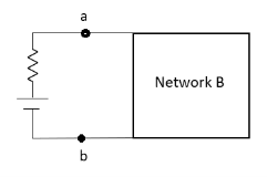
Thevenin’s equivalent of A
Norton’s equivalent of A
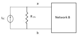
 sc = Vth/Rth
- Norton’s equivalent is obtained by source conversion of thevenin’s equivalent circuit.
CONDITIONS FOR APPLICATION
- For network A:
- Network A should contain linear elements.
- Network A can have independent and dependent current and voltage source.
- If network A has dependent source than controlling parameter must lie in network A itself.
- Network A should not have any source coupling and magnetic coupling.
- For network B:
- It can have linear and non linear elements.
- It can have dependent and independent voltage and current sources.
- It should not have any source and magnetic coupling with network A.
Question:
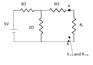
Answer:
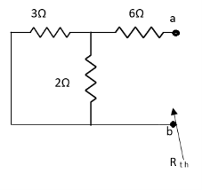


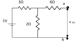


Finding Isc from circuit directly:
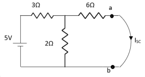
By KCL,


Question:
Answer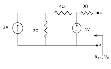
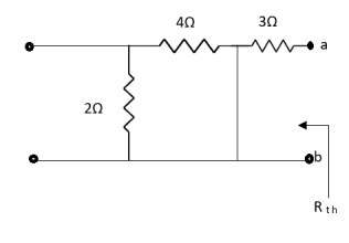
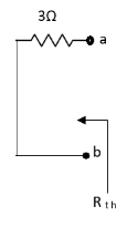
Also, clear from circuit that Vth = 1V.
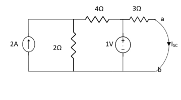
By applying KVL we get,
1-3Isc=0
Isc= A
A
Que:
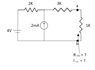
Ans;
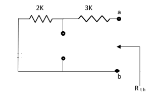
Rth=3k+2k=5k
By applying KVL we get


Therefore, 
Question:
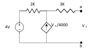
Solution: For Rth
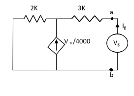
By KCL,


But, 


By KVL,


Question:
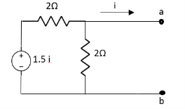
Solution: Since, no independent source is present so,
Isc = 0
And we know that,


Since Rth cannot be zero
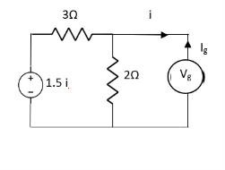


But 


Question: Find out the Norton’s equivalent
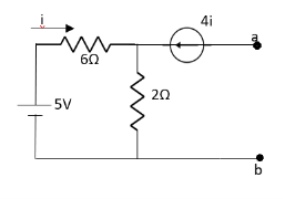
Solution:
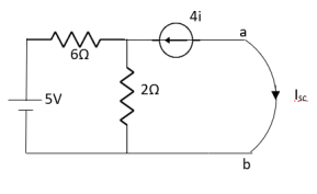
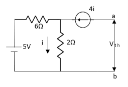

Since, there is no significance of current source


Series R-L circuit:
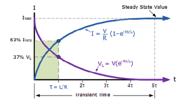
Fig. shows a series RL circuit connected across a DC source through a switch S.
When switch ‘S’ is close at t>0 the as per KVL network equation will be …
R i(t) + L di(t)/dt = Vs ------------------------------------(1)
Above equation is non homogeneous equation linear differential equation of first oder. The solution of equation 1 will give i(t) which consists of two components :
Complimentary function
Which will satisfy di(t)/dt + R/L i(t) =0
Particular integral (if(t)) which will satisfy
R i(t) + L di(t)/dt = Vs
Thus the complete solution wil be
i(t) = in(t) + iJ(t)---------------------------------------(2)
i(t) = Io e –(R/L)t = Io e –(t/ -------------------------------------(3)
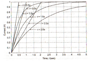
Where  time constant of RL circuit.
Equation (3) provides the natural response where
in(t) = K e –(R/L) t = K e –(t/τ) ----------------------------------(4)
Eq (1) can be written with i(t) = I constnt
RI + L dI/dt = Vs -------------------------------------------(5)
Since I= constsnt
L dI/dt =0
If(t) = I = Vs/R --------------------------------------------(6)
Substitute eq.4 and eq.6 yeilds the solution of eq(1)
i(t) = K e -t/ + Vs/R = K e-t/τ -------------------------------------------(7)
K is determined from initial condition that is t=0 and eq(7) will be
K = -Vs/R = -I ----------------------------------------------------(8)
i(t) = Vs/R (1 – e –(R/L) t)
i(t) = I(1 – e -t/τ) for t>0
Series RC circuit:
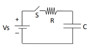
Fig. Shows a series RC circuit connected across a DC source through a switch S.
It is assumed that capacitor voltage id V0 When switch ‘S’ is close at t>0 the as per KVL network
Equation will be …
Vs – R i(t) – vc(t) =0 ------------------------------------------------(9)
For analysis of circuit of the figure the capacitor voltage Vc(t) is chosen as variable .
Substituting i(t) = c dvc(t)/dt in eq(9) we get
Eq(10) is like eq(1) it is also non homogeneous equation linear differential equation
Of first order .
Therefore the solution is similar to eq(1)
Vc(t) = k e -t/τ + Vs ---------------------------------------------(11)
In eq.(11) the time constant is τ = RC
By substituting value of K in eq(11) and after simplification we get --------
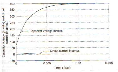
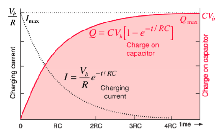
Vc(t) = Vo e (-t/τ) + Vs ( 1 – e -t/τ) V for t>0------------------------------------------(12)
The expression for the current in the circuit is given by ---------
i(t) = C dvc(t)/ dt
i(t) = C [ (-1/τ Vo e -t/τ ) + ((-1/τ Vs e -1/τ )]
i(t) = C/RC (Vs – Vo) e -t/τ
Text-Books/Reference-Books:
- Basic Electrical Engineering - D.P. Kothari and I.J. Nagrath, 3rd edition 2010, Tata McGraw Hill.
- D.C. Kulshreshtha, “Basic Electrical Engineering”, McGraw Hill, 2009.
- L.S. Bobrow, Fundamentals of Electrical Engineering”, Oxford University Press, 2011
- Electrical and Electronics Technology, E. Hughes, 10th Edition, Pearson, 2010
- Electrical Engineering Fundamentals, Vincent Deltoro, Second Edition, Prentice Hall India, 1989.