UNIT 3
Transformers
The B-H curve of transformer core is never linear rather it becomes flat as the value of magnetizing current increases.
This means, transformer exciting current will not be in phase with the core flux. In fact, exciting current leads the core flux by some angle “α”. This angle is known as Hysteretic Angle.
This angle is dependent on the hysteresis loop of the core material.
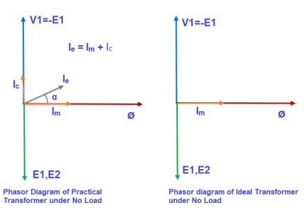
Fig 1 Phasor Diagram for No-Load Transformer
In an ideal transformer, magnetization curve is assumed to be linear. This means, magnetizing current and core flux are in phase.
In practical/real transformer, the exciting current (current in primary winding under no load condition) drawn from the source is composed of magnetizing current (Im) and core loss component (Ic). This is because, core loss is supplied by the primary source only. However, in an Ideal Transformer, as there is no core loss, the exciting current is equal to magnetizing current.
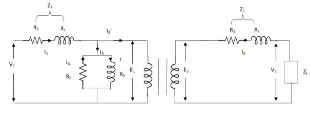
The basic transformer and its equivalent circuit both are shown below,
Fig 2. Equivalent Transformer Circuit
Iµ - magnetising component of current
Iw = working component
R0 – Non- inductive resistance
I0 – No load current
X0 = E1/I0. R0 = E1/Iw
E2/E1 = N2/N1 = K
E’2 = E2/K = E1
V’2 = V2/K
I’2 = K I2
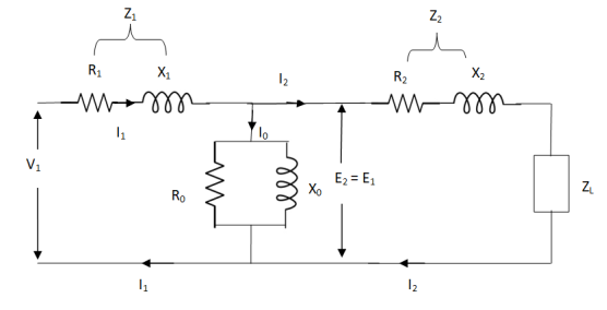
The total equivalent circuit is again given as,
Fig 3 Total Equivalent Circuit
But the above circuit is exact equivalent but harder to solve so, it can be further simplified as,
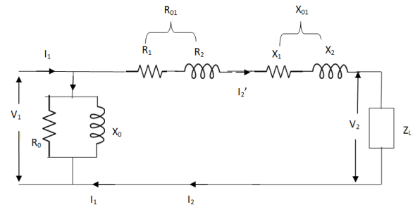
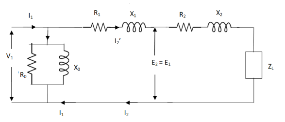
Fig 4 Simplified Equivalent Circuit
Z = Z1 + Zm || ( Z’2 + Z’L )
= Z1 + Zm(Z’2 + Z’L)/Zm + (Z’2 + Z’L)
Z’2 = R’2 + jX’2
Zm = impedance of exciting circuit
V1 = I1[ Z1 + Zm(Z’2 + Z’L) / Zm + (Z’2 + Z’L) ]
Q1>. A 25 KVA transformer has 500 turns on primary and 50 on secondary. The primary is connected to 2000V, 50 Hz supply. Find full load primary and secondary currents, the secondary emf and max flux in core. Neglect leakage drop and no load primary current.
Sol : K = N2/N1 = 50/500 = 1/10
I1 = 25,000/2000 = 12.5 A
I2 = I1/K = 10 x 12.5 A = 125 A
Emf/turn on primary side = 2000/500 = 4 V
E2 = KE1
E2 = 4 x 50 = 200 v
E1 = 4.44fN1 Φm
2000 = 4.44 x 50 x 500 x Φm
Φm = 18.02 m Wb
(1). Core or Iron Loss :
This includes both hysteresis loss and eddy current loss. Iron or core loss is found from open circuit test.
Hysteresis Loss(Wh) = nB1.6max f V Watt
Eddy current Loss(We) = P B2max f2 t2 Watt
(2). Copper Loss :
This is due to ohmic resistance of the transformer windings.
Total cu loss = I21 R1 + I22 R2
= I21 R01 + I22 R02
Cu loss α I2
The value of cu loss is found from short-circuit test.
VOLTAGE REGULATION OF TRANSFORMER:
It can be explained in terms of various parameter of transformer.
(1). When transformer has constant primary voltage.
In this case secondary voltage decreases
0V2 = No-load secondary terminal voltage
0V2 = E2 = EK1 = KV1
V2 = secondary voltage on full-load.
Voltage Regulations is change in secondary terminal voltage from no-load to full load per unit full load voltage.
% regn down = 0V2 – V2/0V2 x 100
% regn up = 0V2 – V2/V2 x 100
(2). Voltage regulation in terms of primary values.
The secondary no-load terminal voltage as referred to primary is E’2 = E2/K = E1 = V1
For secondary full load voltage referred to primary is V’2 = V2/K
% regn = V1 – V’2/V1 x 100
% regn = I1 R01 cosφ + I1 X01 sinφ / V1 x 100
(3). As the transformer is loaded, to maintain a constant output voltage, the primary voltage should be increased. Here the regulation is given as
% regn = V’1 – V1 / V1 x 100
It can also be defined as the change in primary voltage from no-load to full-load at given power factor to maintain a constant output per unit primary voltage.
Q. A – 100 KVA transformer has 500 turns on primary and 80 turns on secondary. The primary and secondary resistances are 0.3 and 0.01 Ω respectively and the corresponding leakage reactances are 1.1 and 0.035 Ω. The supply voltage is 2400 V. Find
(i). Equivalent impedance referred to primary
(ii). Voltage regulation and the secondary terminal voltage for full load having pf 0.8 lagging?
Sol. Equivalent impedance referred to primary
Z01 = √R201 + X201 = R01 + jX01
R01 = R1 + R2/K2 = 0.3 + 0.01/K2 = 0.69 Ω
K = 80/500 = 4/25
X01 = X1 + X2/K2 = 1.1 + 0.035/(0.16)2 = 2.467 Ω
Z01 = 0.69 + j2.46
(ii). Secondary terminal voltage Z02 = K2 Z01
Z02 = 0.018 + j 0.063
= 0.065 ( 74.050
No-load secondary voltage = KV1
= 0.16 x 2400 = 384 V
I2 = 100 x 103/384 = 260.42 A
Full load voltage drop referred to secondary
= I2 (R02 cosφ – X02 Sinφ)
Cosφ = 0.8
Φ = 36.860
Sinφ = 0.6
= 260.42(0.018 x 0.8 – 0.063 x 0.6)
= - 6.094 V
% regn = -6.094/384 x 100
= -1.587
Secondary terminal voltage on-load
= 384 – (-6.094)
= 390.09 V
Resistance, reactance & Impedance :
(i). % resistance at full-load
% R = I1R01/V1 x 100 = I21 Ro1/V1I1 x 100
= I22 R02/V2I2 x 100 = % w – loss at full load
(ii). % Reactance at full-load
% X = I1 X01/V1 x 100 = I2 X02/V2 x 100
(iii). % impedance at full-load
% Z = I1Z01/V1 x 100 = I2 Z02/V2x 100
% Z = √%R2 + %X2
Efficiency of transformer :
Basically efficiency is defined as
n = output/input
But for transformer there are small amount of losses so the improved way to find efficiency is
n = output/output + losses
n = output/output + cu loss + iron loss
Or n = Input – losses/Input
= 1 – Losses/Input
Condition for maximum efficiency :
For n to be maximum dn/dI1 = 0
(Ww) cu loss = I21 R01 or I22 R02
Iron loss = Hysteresis loss + Eddy current loss
= Wn + We = Wi
n = Input – losses/Input
Primary Input = V1I1 Cosφ1
n = V1 I1 Cosφ1 – losses/V1 I1 cos φ1
n = V1 I1 cos φ1 – I21 R01 – Wi / V1I1 cosφ1
= 1 – I1R01/V1cosφ1 – Wi/V1I1cosφ1
Differentiating w.r.t I1 both sides of above equation we have
Dn/dI1 = 0 – R01/V1cosφ1 + Wi/V1I21 Cosφ1
For max value dn/dI1 = 0
R01/V1cosφ1 = Wi/V1I21 cosφ1
Wi = I21 = I21 R01
Hence,
Wi = Wcu
Iron loss = copper loss
The value of output current for maximum efficiency will be
I2 = √Wi/R02
The maximum efficiency can also be given as,
nmax = full load x √ Iron loss / F.L .cu loss
Or
nmax = R’ x full load KVA x pf / R’ x full load KVA x pf + Wi + Wcu x 100
R’ = ratio of actual to full load KVA
Wi = iron loss (KW)
Wcu = copper loss (KW)
Q1). In a 50 KVA, 2200/200 V, 1-φ transformer, the iron and full-load copper losses are 400 W and 450 W respectively. Calculate n at unity power factor on (i). Full load (ii). Half-full load?
Sol. (i). Total loss = 400 + 450 = 850 W
F.L output at unity power factor = 50 x 1
= 50 KVA
n = 50 / 50 + .850 = 50/50.850 = 0.98 = 98%
(ii). Half full load, unity pf
= 50 KVA/2 = 25 KVA
Cu loss = 400 x (1/2)2 = 100 W
Iron loss is same = 450 W
Total loss = 100 + 450 = 550 W
n = 25/25 + 0.55 = 25/25.55 = 0.978 = 97.8 %
Q>. A 40 KVA 440/220 V, 1- φ, 50 Hz transformer has iron loss of 300 W. The cu loss is found to be 100 W when delivering half full-load current. Determine (i) n when delivering full load current at 0.8 lagging pf (ii) the percentage of full-load when the efficiency will be max.
Sol. Full load efficiency at 0.8 pf
= 40 x 0.8/(40 x 0.8) + losses
Full load cu loss = (440/220)2 x 100
= 400 W
Iron loss = 400 + 300
= 700 W
n = 40 x 0.8/(40 x 0.8) + 0.7 = 97.8 %
(ii). KVA for maximum / F.L KVA = √ iron loss / F.L cu loss
= √300/400 = 0.866
An auto Transformer is a special types of transformer such that a part of the winding is common to both primary as well as secondary
It has only One winding wended on a laminated magnetic core
With the help of auto Transformer the voltage can be stepped up and stepped down at any desired value
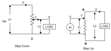
Fig 5 Step up and Step-Down Auto Transformer
Fig A shows auto T/F as step down T/F variable terminal B C is connected to load and it acts as secondary winding.
The position of point C is called as topping point can be selected as per requirement
Fig. B show auto T/F as step up T/F variable terminal B C is connected to supply side ie ac side and it acts as secondary winding
The operating principle of auto Transformer is same as that of 2 winding Transformer
Advantages
- Weight of copper required in an auto Transformer is always loss than that of the conventional 2 winding Transformer and hence it is chapter
- Compact in size and loss costly.
- Losses taking place in Transformer is reduced hence efficiency is higher than conventional Transformer.
- Due to reduced resistance, voltage, regulation is better than conventional T/F.
Disadvantage:
As low voltage and high voltage sides are not separate then there is always risk of electric shocks when use for high voltage. Applications
Applications
- Starting squirrel cage induction motor and synchronous motor.
- Auto transformer as dimmer stat
- Used as vari ac to vary a. c Voltage
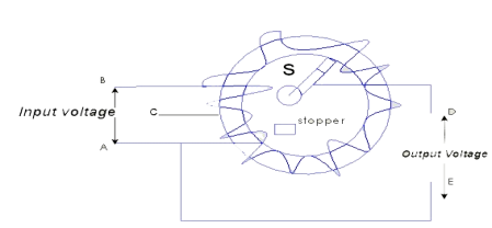
Fig 6 Auto transformer
Q. An auto transformer suppliers load of 4KW at 100v at unity pf. IF the applied primary voltage is 220v. Calculating power transferred to load (a) Inductively (b) conductively.
Soln, Power transferred inductively = Input(1-k)
Power transferred conductively = K* Input
K=  =
=
Input= Output =4KW
Inductively transferred power =4( )
)
=3.82KW
Conductively transferred power =  *4
*4
= 0.182 kW
As the supply is in 3-phase so we need this transformer. Its alternating voltage and currents differ in phase by 120 degrees.
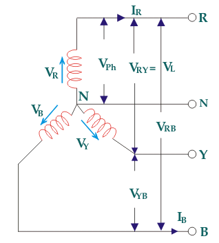
Fig7: Three phase Transformer
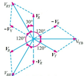
Fig8: Line and phase voltage
Construction:
a) Core Type:
The construction of a core type three phase transformer is as shown in the figure. The core consists of three legs or limbs. The core is made up of thin laminated sheets to reduce eddy current losses. Each limb has primary and secondary windings in cylindrical shape (former wound) arranged concentrically. The construction is shown in the figure.
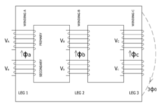
Fig 9: Core type 3-phase transformer
b) Shell Type:
In a shell type three phase transformer, three phases are more independent than they are in core type. Each phase has its individual magnetic circuit. The construction of shell type three phase transformer is illustrated in the figure at right. The construction is similar to that of three single phase shell type transformers kept on the top of each other.
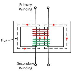
Fig 10: Shell Type 3-phase Transformer
Types of connection and comparative features
Star – star or Y/Y connection: -
The below figure shows transformers connected in Y/Y on both primary and secondary sides. The ratio of line voltage and transformation ratio of line voltage and transformation ratio of both primary and secondary of each transformer in same. Hence the phase voltage VP =  . VLine (line voltage)
This connection works only if the load is balanced.
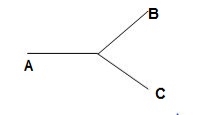
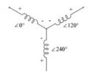
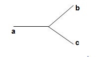
Fig 11: Three phase transformer Y-Y connection
- The effect of unbalanced load can be balanced by placing single load between a and n on secondary.
- Power to load is supplied by primary side A.
- As, A is in series with B and C and has b and c open on secondary, so it cannot supply required power.
- Now, B and C acts as high impedance in this condition, allowing very less flow of current in A.
- A low resistance can be connected between a and n which is approaching to short circuit. So, small current flows.
- Hence, EAN will reduce to zero but EBN and ECN will rise to full primary line voltage.
- The above shown connection is most economical for small, high-voltage transformers because the number of turns per phase and the amount of installation required is minimum.
- One more advantage is that the installation is stressed to the extent of line to neutral voltage i.e. 58% of line voltage.
- For having a sine wave voltage at output it is necessary that sine wave of flux should be in the core. To fulfil this we require third harmonic component of exciting current.
- To attain this if primary neutral is isolated then triple current cannot be attained. So, the best way is to provide a territory winding to each transformer of 1000 kVA rating.
Delta – Delta or Δ – Δ connection: -
- In this connection the ratio of transformation between both primary and secondary line voltage is same.
- There is no internal phase shift between phase and line voltages on either side as it was in Y-Y connection.
- The third harmonic component of current can flow in the Δ-connected transformer primaries.
- The balancing of load is easy unlike Y-Y connections.
- As the phases are 120˚ apart w.r.t. third harmonic, the flux is sinusoidal which results in sinusoidal voltages.
- If anyone transformer becomes disabled. The system can continue to operate in open delta or V-V connection.
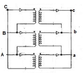
Fig 12: Δ-Δ connection
Wye / Delta or Y/Δ connections: -
- It is mainly used at the subtraction where the voltage is to be stopped down.
- Primary winding is Y connected and the ratio of secondary & primary line voltage is 1/
 .
. - There is 30˚Ø-shift between primary & secondary of line voltage.
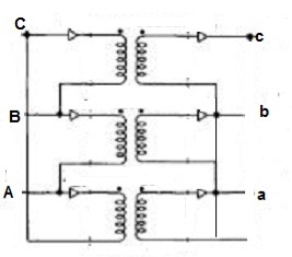
Fig 13: Y/Δ connection
Delta/Wye or Δ/Y connection:-
- It is used where we need to stop up the voltage.
- The primary and secondary line voltages and line currents are out of phase with each other by 30˚.
- The ratio of secondary to primary voltage is
 times of the transformation ratio of each transformer.
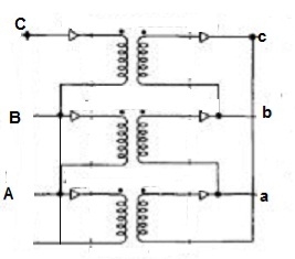
Fig 14: Δ-Y connection
Comparative features:
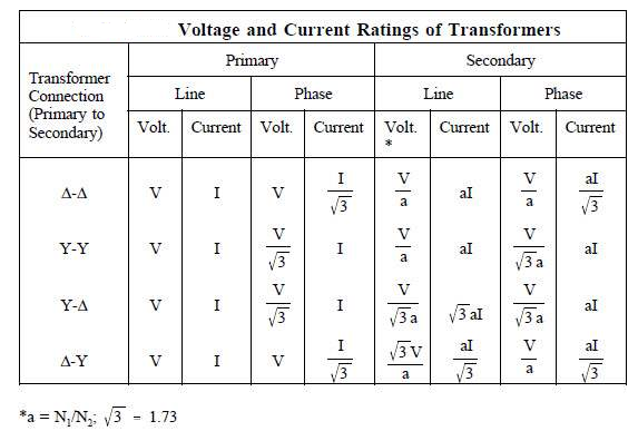
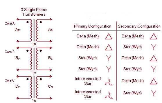
Que 1. A 3-Ø, 50Hz transformer has delta connected primary and star-connected secondary, the line voltage being 20,000 V and 500 V respectively. The secondary has a star connected balanced load at 0.8 lagging p.f. The line current of primary side is 5A. Determine the current in each coil of the primary and secondary line. Also find the output of the transformer?
→ Phase voltage on primary side = 20,000 V
Phase voltage on secondary =  V
V
K = 
Primary phase current = 
Secondary phase current = 
= 
= 200 A
Output =  VLILcosØ
= 
= 138.56 kW
Que 2. A 100 kVA, 3Ø, 50 Hz , 3500/500 V transformer is Δ – connected on the h. V side and Y-connected on the L.V. Side. The resistance of h.V. Winding is 3.5 Ω / phase and that of L.V is 0.02 Ω per phase. Calculate the iron losses of the transformer at normal voltage and frequency if its full load efficiently be 95.1 % at 0.8 p.f. ?
→ Full load output = 100 × 0.8 = 80 kW
Input =  kW
kW
Total loss = Input – Output
= 83.2 – 80
= 3200 kW
K = 
K = 
= 
RO2 = R2 + k2R1
= 
= 0.044 Ωs
Full-load secondary phase current I2
= 
= 115.4 A
Total Cu Loss = 3I22RO2
= 3 × 0.044 × (115.4)2
= 1760 W
Iron Loss = Total loss – Cu Loss
= 3200 – 1760
= 1440 W
Reference:
- Basic Electrical Engineering - D.P. Kothari and I.J. Nagrath, 3rd edition 2010, Tata McGraw Hill.
- D.C. Kulshreshtha, “Basic Electrical Engineering”, McGraw Hill, 2009.
- L.S. Bobrow, Fundamentals of Electrical Engineering”, Oxford University Press, 2011
- Electrical and Electronics Technology, E. Hughes, 10th Edition, Pearson, 2010
- Electrical Engineering Fundamentals, Vincent Deltoro, Second Edition, Prentice Hall India, 1989.