UNIT 2
Orthographic Projections
If straight lines are drawn from various points on the contour of an object to meet a plane, the object is said to be projected on that plane. The figure formed by joining, in correct sequence, the points at which these lines meet the plane, is called the projection of the object. The lines from the object to the plane are called projectors.
Methods of Projection:
Following four methods of projection are commonly used,
1) Orthographic projection.
2) Isometric projection.
3) Oblique projection.
4) Perspective projection.
In the above methods 2, 3 and 4 represent the object by a pictorial view as eyes see it. In these methods of projection, a three-dimensional object is represented on a projection plane by one view only, while in the orthographic projection an object is represented by two or three views on the mutual perpendicular projection planes. Each projection view represents two dimensions of an object. For the complete description of the three-dimensional object at least two or three views are required.
Projection of Points
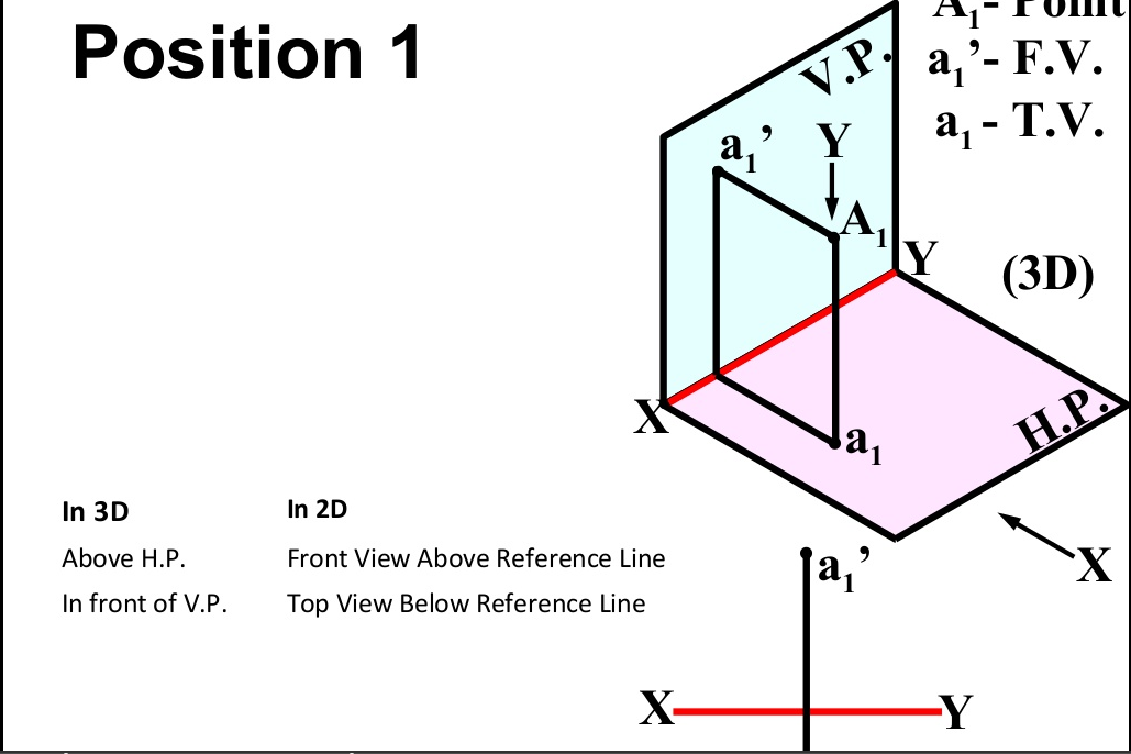
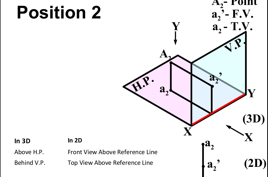
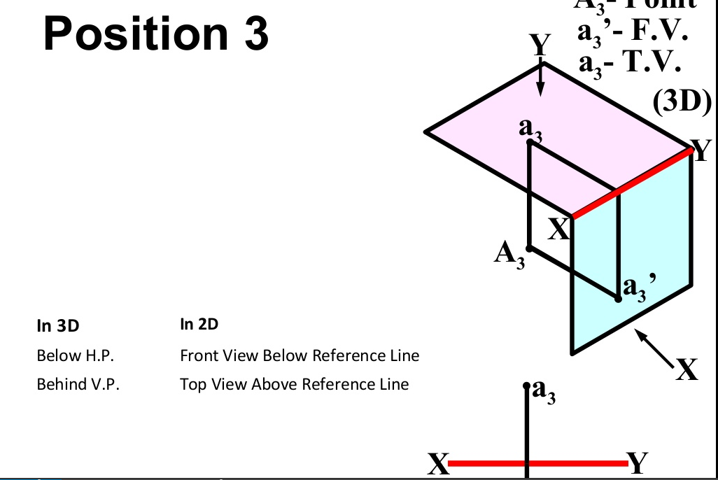
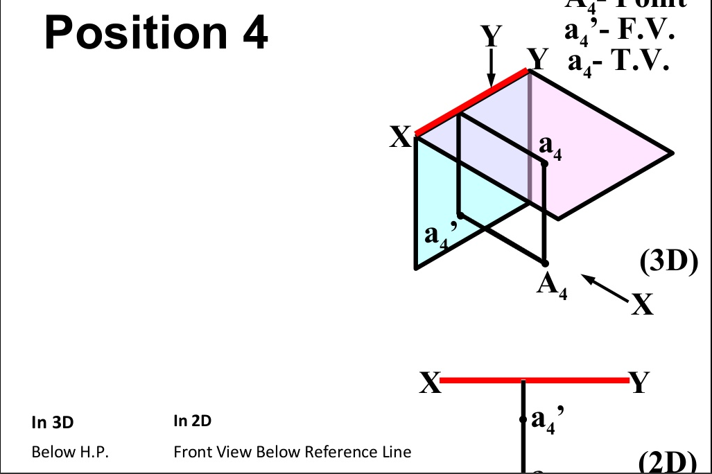
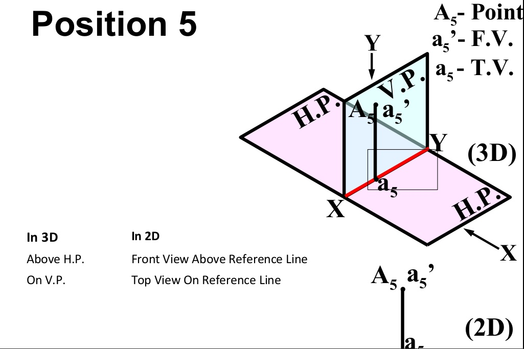
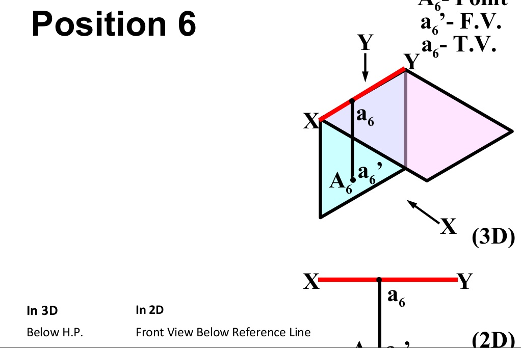
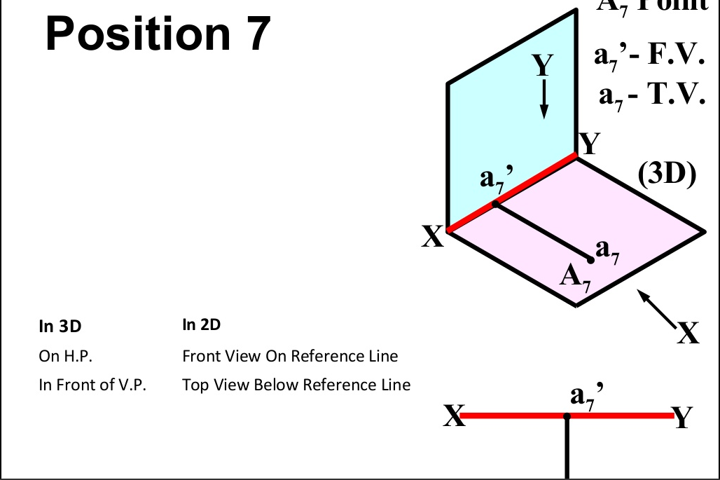
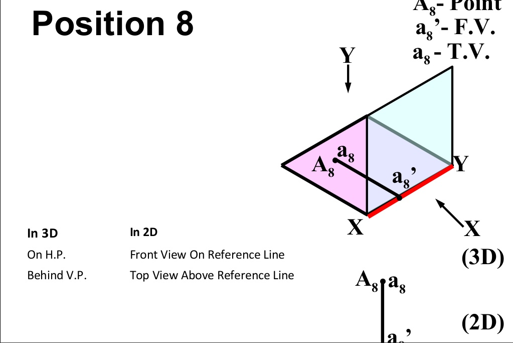
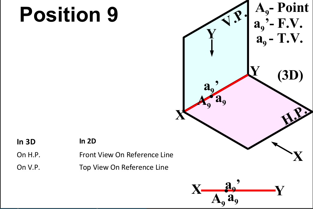
There are basically nine type of projections of point is space :
- In FIRST Quadrant (Above H.P. , In front of V.P.)
- In SECOND Quadrant (Above H.P. , Behind V.P.)
- In THIRD Quadrant (Below H.P. , Behind V.P.)
- In FOURTH Quadrant (Below H.P. , In front of V.P.)
- In PLANE (On V.P. , Above H.P.)
- In PLANE (On H.P. , Behind V.P.)
- In PLANE (On V.P. , Below H.P.)
- In PLANE (On H.P. In front of V.P.)
- In PLANE (On both H.P. & V.P.)
Projection Of Lines
A straight line is the shortest distance between two points.
Top views of two end points of a straight line, when joined, give the top view of the straight line.
Front views of the two end points of a straight line, when joined, give the front view of the straight line. Both the above projections are straight lines.
Notations for : Projection Of Lines
- True length of the line: Denoted by Capital letters. e.g. AB=100 mm, means that true length of the line is 100 mm.
- Front View Length: Denoted by small letters. e.g. a’b’=70 mm, means that Front View Length is 70 mm.
- Top View Length: Denoted by small letters. e.g. Ab=80 mm, means that Top View Length is 80 mm.
- Inclination of True Length of Line with H.P.: It is denoted by θ. e.g. Inclination of the line with H.P. (or Ground) is given as 30º means that θ = 30º.
- Inclination of True Length of Line with V.P.: It is denoted by Φ. e.g. Inclination of the line with V.P. Is given as 40º means that Φ = 40º.
- Inclination of Front View Length with XY : It is denoted by α. e.g. Inclination of the Front View of the line with XY is given as 50º means that α = 50º.
- Inclination of Top View Length with XY : It is denoted by β. e.g. Inclination of the Top View of the line with XY is given as 30º means that β = 30º.
- End Projector Distance: It is the distance between two projectors passing through end points of F.V. & T.V. Measured parallel to XY line.
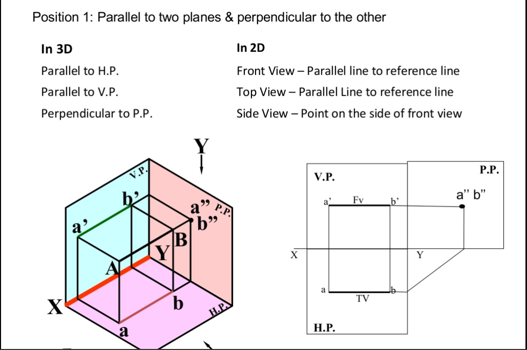
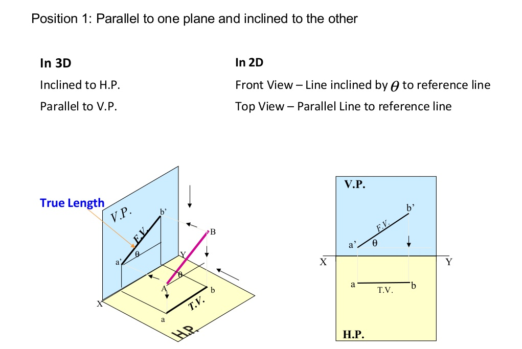
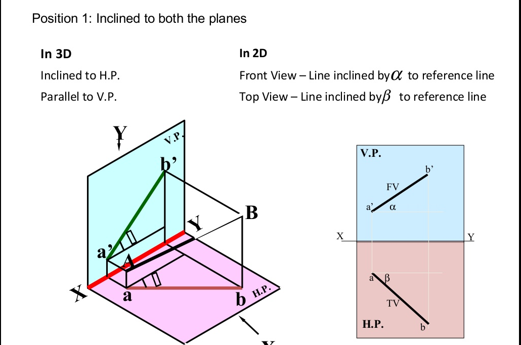
Projection Of Lines There are cases of projections of line
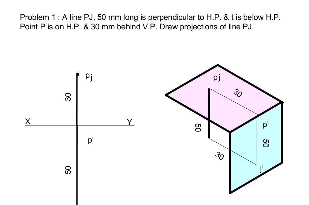
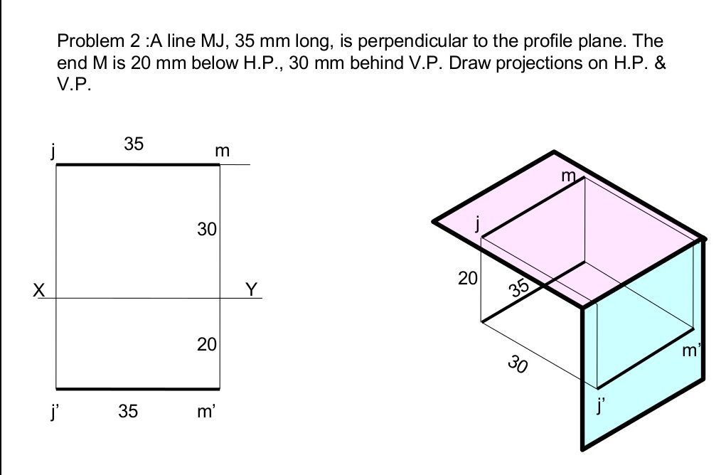
- Line Parallel to two Planes and Perpendicular to the third plane.
- Line Inclined to one Plane and Parallel to another.
- Line Inclined to both the Planes.
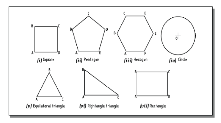
A plane is a two dimensional object having length and breadth only. Its thickness is always neglected. Various shapes of plane figures are considered such as square, rectangle, circle, pentagon, hexagon, etc.
PROJECTIONS OF PLANES
- To draw their projections means F.V, T.V. & S.V.
What will be given in the problem?
- Description of the plane figure.
- It’s position with HP and VP.
In which manner it’s position with HP & VP will be described?
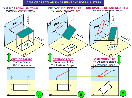
- Inclination of it’s SURFACE with one of the reference planes will be given
- Inclination of one of it’s EDGES with other reference plane will be given (Hence this will be a case of an object inclined to both reference Planes.)
References:
1. Engineering Drawing N.D. Bhatt / Charotar
2. Engineering Drawing / N. S. Parthasarathy and Vela Murali/ Oxford
3. Engineering Drawing / Basant Agrawal and McAgrawal/ McGraw Hill
4. Engineering Drawing/ M. B. Shah, B.C. Rane / Pearson.
5. Computer Aided Engineering Drawing – K Balaveera Reddy et al – CBS Publishers