UNIT 2
HARMONIC OSCILLATIONS
MECHANICAL SIMPLE HARMONIC OSCILLATORS
The figure-1 depicts simple mechanical oscillator having mass attached to the spring. This structure is similar to Pendulum. It is also known as harmonic oscillator.
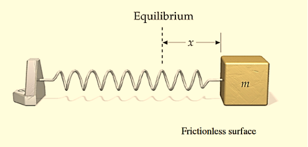
Figure 1: Simple Mechanical Oscillator
If a body attached to a spring is displaced from its equilibrium position, the spring exerts a restoring force on it, which tends to restore the object to the equilibrium position. This force causes oscillation of the system, or periodic motion.
When the restoring force is directly proportional to the displacement from equilibrium, the resulting motion is known as simple harmonic motion and the oscillator is known as Harmonic Oscillator.
In this type of system body itself changes its position.
For mechanical oscillation two things are especially responsible i.e. Inertia & Restoring force.
Differential Equation
A particle is said to be execute simple harmonic oscillation is the restoring force is directed towards the equilibrium position and its magnitude is directly proportional to the magnitude and displacement from the equilibrium position. If F is the restoring force on the oscillator when its displacement from the equilibrium position is x, then
F –x
–x
Here, the negative sign implies that the direction of restoring force is opposite to that of displacement of body i.e. towards equilibrium position.
F= -kx ............. (1)
Where, k= proportionality constant called force constant.
An example of such a simple system is the mass m, attached to a spring of stiffness k.
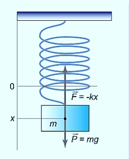
Figure 2: Spring Mass System
In the case of a mass on a spring, the restoring force for small oscillations obeys Hooke’s law:
F=−kx,
Where k is the stiffness of the spring. Here the coordinate x=0 corresponds to the point of equilibrium, in which the force of gravity is balanced by the initial tension of the spring.
Then, according to Newton’s second law, the movement of the mass will be described by the differential equation
Mx′′=−kx,
⇒x′′+ x=0.
x=0.
Solution of differential equation is
x= Acosωt
Thus, the mass on the spring will perform undamped harmonic oscillations with the circular frequency
ω=
The period of oscillation, respectively, will be equal to
T=  = 2π
= 2π 
A similar analysis of other oscillatory system – a simple (mathematical) pendulum – leads to the following formula for the oscillation period:
T=2π 
Where L is the length of the pendulum, g is the acceleration of gravity.
In the case of a compound or physical pendulum, the period of oscillation is given by
T=2π 
Where I is the moment of inertia of the pendulum about the pivot point, m is the mass of the pendulum, a is the distance between the pivot point and the center of mass of the pendulum.
Example: oscillation of mass spring system, oscillation of fluid-column in a U-tube, oscillation of simple pendulum, rotation of earth around the sun, oscillation of body dropped in a tunnel along earth diameter, oscillation of floating cylinder, oscillation of a circular ring suspended on a nail, oscillation of atoms and ions of solids, vibration of swings etc.
ELECTRICAL SIMPLE HARMONIC OSCILLATORS
Whenever we connect a charged capacitor to an inductor the electric current and charge on the capacitor in the circuit undergoes LC Oscillations. The process continues at a definite frequency and if no resistance is present in the LC circuit, then the LC Oscillations will continue indefinitely.
This circuit is known as an LC oscillator. Let’s take a capacitor with capacitance C and an inductor with inductance L. The capacitor is fully charged with charge Qo. What we do here is to connect the capacitor and the inductor end to end.
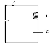
Figure 3: Electrical Simple Harmonic Oscillators
Assuming the inductor and capacitor to be ideal (meaning resistance will be zero in the overall circuit). Initially, the capacitor C of the LC circuit carries a charge Qo and current I in the Inductor is zero. Therefore at time T = 0, the charge on the capacitor will be:
q(T=0)=Qo
Current Flowing: I=0
At time T = t, the capacitor now begins to discharge through the inductor. The current begins to flow in an anti-clockwise direction. Therefore the charge of the capacitor decreases, but the energy of the inductor increases. The energy gets transferred from the capacitor to the inductor.
At this stage, there is the maximum value of the current in the inductor. Then the relationship between the current and the charge will be:
I=− …………..(1)
The negative sign is added because as the time passes from 0 to t the, charge on the plates of capacitor decreases i.e. charge decreases with respect to time and thus the dq/dt obtained will be negative and this is why we add a negative sign to make a current positive.
Applying Energy Conservation
Since, Heat Loss = 0 and Kinetic Energy = 0. Total energy which is constant is given by:
 ×
× +
+ ×LI2=Eo
Now initially we had charge Qo and current flowing was zero I=0. So, the total energy at T = 0, will only be the energy stored in the capacitor and energy stored in the inductor will be zero.
Eo= ×
×
Now on equating the value of total energy we get:
 ×
× +
+ ×LI2=
×LI2= ×
×
On differentiating with respect to t we get:
 ×
×
 +
+ ×2LI
×2LI =
=
On further calculation we get the equation as:
L =
= 
Substituting the value of I from equation 1 we get:
 =
=  q …………..(2)
 +
+ q =0 …………..(3)
 + ω2q =0 …………..(4)
Upon comparing (2) and (3), we have
ω2 = 
ω =  …………..(5)
And now double differentiating equation 1 with respect to t we get:
 =
=  I …………..(6)
We can see that the above both the equation 2 and 6 of Charge and Current both represent the Simple Harmonic Motion. That is both charge and current are oscillating as a simple harmonic waves with respect to time.
Solution of Simple Harmonic Motion Equation
In general charge as a function of time in SHM will be given as:
q(t)=Qocos(ωt)
Where angular frequency ω = 
The figure-3 depicts electrical analogy of the mechanical oscillator. This is example of electronic or electrical oscillator. There are different types of oscillators viz. RC oscillator, LC oscillator, crystal oscillator etc.
Key Takeaways
- Simple mechanical oscillator having mass attached to the spring.
- A particle is said to be execute simple harmonic oscillation is the restoring force is directed towards the equilibrium position and its magnitude is directly proportional to the magnitude and displacement from the equilibrium position.
- Differential Equation is given by x′′+ ω2x=0 and Solution of differential equation is given by x= Acosωt
- The mass on the spring will perform undamped harmonic oscillations with the circular frequency ω=

- The time period of oscillation will be equal to T=
 = 2π
= 2π 
- Whenever we connect a charged capacitor to an inductor the electric current and charge on the capacitor in the circuit undergoes LC Oscillations. The process continues at a definite frequency and if no resistance is present in the LC circuit, then the LC Oscillations will continue indefinitely. This circuit is known as an LC oscillator.
- Differential Equation of electrical simple harmonic oscillators is given by
 +
+ q =0 and frequency is given by ω =
The square root of −1, called i, is important in physics and mathematics for many reasons. Measurable physical quantities can always be described by real numbers. You never get a reading of I meters on your meter stick. However, we will see that when i is included along with real numbers and the usual arithmetic operations (addition, subtraction, multiplication and division), then algebra, trigonometry and calculus all become simpler. While complex numbers are not necessary to describe wave phenomena, they will allow us to discuss them in a simpler and more insightful way.
An imaginary number is a number of the form i times a real number. A complex number, z, is a sum of a real number and an imaginary number: z=a+ib.
The real and “imaginary” parts, Re(z)and Im(z), of the complex number z=a+ib: Re(z) =a ,Im(z) =b
Note that the imaginary part is actually a real number, the real coefficient of i in z=a+ib.
The complex conjugate, z*, of the complex number z, is obtained by changing the sign of i:
z∗=a−ib
Note that Re (z) = (z+z∗)/2 and Im (z) = (z−z∗)/2i
The complex plane: Because a complex number z is specified by two real numbers, it can be thought of as a two-dimensional vector, with components (a,b).
The real part of z, a=Re (z), is the x component and the imaginary part of z, b=Im (z), is the y component.
The absolute value, |z|, of z, is the length of the vector (a,b):
|z|=  = z∗z
= z∗z
The absolute value |z| is always a real, non-negative number.
The diagrams in figures 4 and 5 show two vectors in the complex plane along with the corresponding complex numbers:
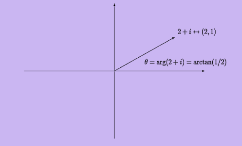
Figure 4 : A vector with positive real part in the complex plane.
The argument or phase, arg(z), of a nonzero complex number z, is the angle, in radians, of the vector (a,b) counter clockwise from the x axis:

Like any angle, arg(z)can be redefined by adding a multiple of 2π radians or 360◦
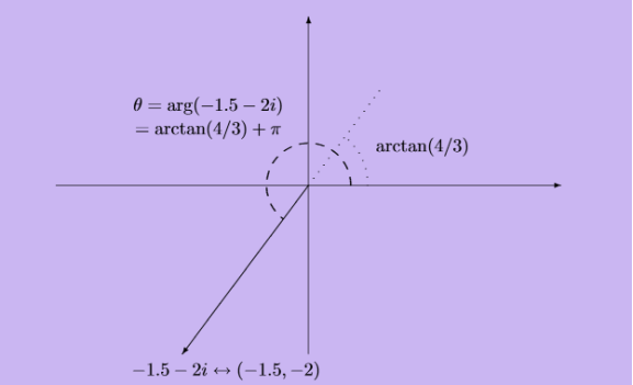
Figure 5: A vector with negative real part in the complex plane
Describing Real Circling Motion in a Complex Way
Because the HO equation of motion is linear and homogeneous, linear combinations of solutions are also solutions. These linear combinations can be complex combinations.
We’ve seen that any complex number can be written in the form z=reiθ, where r is the distance from the origin, and θ is the angle between a line from the origin to z and the x -axis. This means that if we have a set of numbers all with the same r, but different θ ’s, such as reiα, reiβ, etc., these are just different points on the circle with radius r centered at the origin in the complex plane.
Now think about a complex number that moves as time goes on: z(t)=Aeiωt.
At time t, z(t) is at a point on the circle of radius A at angle ωt to the x -axis. That is, z(t) is going around the circle at a steady angular velocity ω. We can also write this:
z(t)=Aeiωt=Acosωt + I Asinωt
And see that the point z=x+iy is at coordinates (x,y)=(Acosωt, Asinωt).
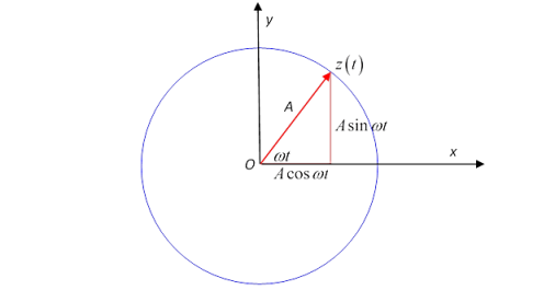
Figure 6: Describing Real Circling Motion in a Complex Way
The angular velocity is ω, the actual velocity in the complex plane is dz(t)/dt.
Let’s differentiate with respect to time:
 (Aeiωt )=
 A(cosωt+isinωt)
=iω Aeiωt
=iωA(cosωt+isinωt)
=iωAcosωt−ωAsinωt.
Now the x and y components of this velocity regarded as a vector. We will See that it is perpendicular to the position vector.
This differential equation has real and imaginary parts on both sides, so the real part on one side must be equal to the real part on the other side, and the same for imaginary parts. That gives
 cosωt=−ωsinωt,
  sinωt=ωcosωt
So differentiating the exponential is consistent with the standard results for trig functions. Differentiating one more time,
 Aeiωt=−ω2Aeiωt
Again going to the picture of a complex numbers as a two-dimensional vector, this is just the acceleration of an object going round in a circle of radius A at angular velocity ω, and is just Aω2 towards the center of the circle, the familiar rω2=v2/r. Thinking physics here, this is the motion of an object subject to a steady central force.
PHASOR REPRESENTATION OF SIMPLE HARMONIC MOTION
We have seen that a uniform circular motion can be associated with one-dimensional SHM. In this association a diameter of the circle is taken as the x-axis, and the SHM appears as the x-component of the motion around the circle. Sometimes the SHM is described as the projection of the circular motion along the diameter. The reason why this is useful is that it gives a clear visual representation of the three characteristics which define any SHM the amplitude, the frequency and the phase.
The amplitude corresponds to the radius of the circle, the frequency to the number of rotations of the object around the circle in unit time and the phase to the angle θ between the x-axis and the line joining the centre of the circle to the position of the rotating object at the time concerned. In fact, this simple geometrical construction is even more useful than we have shown so far.
This new representation is called the phasor model and is illustrated in Figure 7.
Figure 7 has much in common with Figure 8 though a y-axis has been added for later convenience.
Where Figure 8 depicted uniform circular motion. Nonetheless, the main difference is one of terminology in that the displacement vector  of the circular motion will hence forth be referred to as the displacement phasor of the simple harmonic motion. The length of the phasor, A, is called its amplitude while the angle θ between the phasor and the x-axis is called its phase.
In principle we can now describe a given SHM in terms of its associated (rotating) displacement phasor we need not think about circular motion at all. Phasor diagrams similar to Figure 7 can be drawn to represent the displacement, velocity, or acceleration of the oscillating object at any given time that is to give the amplitude and phase of the displacement, velocity, or acceleration at that time.
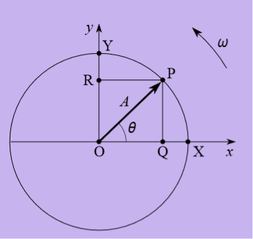
Figure 7: The phasor model for one-dimensional SHM.
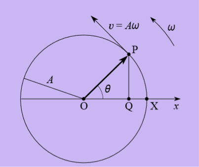
Figure 8: An object in uniform circular motion with an orbit radius A, an angular speed ω and an orbital speed v = Aω.
But what if we just equate the real parts of both sides? That must be a perfectly good equation: it is
 Acosωt=−ω2Acosωt
This is just the x -component of the circling motion, that is, it is the “shadow” of the circling point on the x -axis.
Forgetting for the moment about the circling point, and staring at just this x -axis equation, we see it describes the motion of a point always having acceleration towards the origin (that is, the minus sign ensures the acceleration is in the opposite direction to that of the point itself from the origin) and the magnitude of the acceleration is proportional to the distance of the point from the origin.
In fact, motion of this kind is very common in nature! It is called simple harmonic motion.
Key Takeaways
- Complex number is given by z=a+ib and the complex conjugate is given by, z* =a−ib
- The absolute value, |z|, of z, is the length of the vector (a,b):|z|=

- The absolute value |z| is always a real, non-negative number.
- The SHM is described as the projection of the circular motion along the diameter. This gives a clear visual representation of the three characteristics which define any SHM the amplitude, the frequency and the phase.
We have seen that the total energy of a harmonic oscillator remains constant. Once started, the oscillations continue forever with a constant amplitude (which is determined from the initial conditions) and a constant frequency (which is determined by the inertial and elastic properties of the system). Simple harmonic motions which persist indefinitely without loss of amplitude are called free or undamped.
However, observation of the free oscillations of a real physical system reveals that the energy of the oscillator gradually decreases with time and the oscillator eventually comes to rest. For example, the amplitude of a pendulum oscillating in the air decreases with time and it ultimately stops. The vibrations of a tuning fork die away with the passage of time. This happens because, in actual physical systems, friction (or damping) is always present. Friction resists motion.
The presence of resistance to motion implies that frictional or damping force acts on the system. The damping force acts in opposition to the motion, doing negative work on the system, leading to a dissipation of energy. When a body moves through a medium such as air, water, etc. its energy is dissipated due to friction and appears as heat either in the body itself or in the surrounding medium or both.
There is another mechanism by which an oscillator loses energy. The energy of an oscillator may decrease not only due to friction in the system but also due to radiation. The oscillating body imparts periodic motion to the particles of the medium in which it oscillates, thus producing waves. For example, a tuning fork produces sound waves in the medium which results in a decrease in its energy.
All sounding bodies are subject to dissipative forces, or otherwise, there would be no loss of energy by the body and consequently, no emission of sound energy could occur. Thus, sound waves are produced by radiation from mechanical oscillatory systems. The electromagnetic waves are produced by radiations from oscillating electric and magnetic fields.
The effect of radiation by an oscillating system and of the friction present in the system is that the amplitude of oscillations gradually diminishes with time. The reduction in amplitude (or energy) of an oscillator is called damping and the oscillation are said to be damped.
When the energy of a oscillating system is gradually dissipated by friction and other resistances, the oscillations are said to be damped. The oscillations gradually reduce or change in frequency or intensity or cease and the system rests in its equilibrium position.
Damped oscillations refer to oscillations where the oscillating object loses its energy to the surroundings.
Damping, in physics, restraining of vibratory motion, such as mechanical oscillations, noise, and alternating electric currents, by dissipation of energy. Unless a child keeps pumping a swing, its motion dies down because of damping. Shock absorbers in automobiles and carpet pads are examples of damping devices.
A system may be so damped that it cannot oscillate. Critical damping just prevents oscillation or is just sufficient to allow the object to return to its rest position in the shortest period of time.
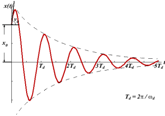
Figure 9: Damped Oscillations
There are many types of mechanical damping. Friction, also called in this context dry, or Coulomb, damping, arises chiefly from the electrostatic forces of attraction between the sliding surfaces and converts mechanical energy of motion, or kinetic energy, into heat. The motion of a oscillating body is also checked by its friction with the gas or liquid through which it moves.
Damped Oscillations
In real systems, there is always a resistance or friction, which leads to a gradual damping of the oscillations. In many cases, the resistance force (denoted by FC) is proportional to the velocity of the body, that is
FC=−cx′.
Then, taking into account the force of resistance, the differential equation for the “mass-spring” system is written as
Mx′′+cx′+kx=0, ⇒ x′′+  x′+
x′+ x=0
x=0
We introduce the following notations:  =2β,
=2β,  =
=  . Here ω0 is the natural frequency of the undamped oscillator (previously, we denoted it as ω), β is the damping coefficient. In the new notations, the differential equation looks like
x′′+2βx′+ x=0.
x=0.
We will seek the solution of this equation as a function
x(t)=Aeλt.
The derivatives are given by
x′(t)=Aλeλt, x′′(t)=Aλ2eλt.
Substituting this into the differential equation, we obtain the algebraic characteristic equation:
Aλ2eλt+2βAλeλt+ Aeλt=0,
⇒λ2+2βλ+ =0.
=0.
The roots of this equation are
D=4β2−4 ,
,

It can be seen that depending on the sign of the radicand β2− , there may be three different types of solutions.
Case 1. Overdamping or Heavy Damping: β>ω0
When resistance to motion is.very strong, the system is said to be heavily damped. Can you name a heavily damped system of practical interest? Springs joining wagons of a train constitute the most important heavily damped system. In your physics laboratory, vibrations of a pendulum in a viscous medium such as thick oil and motion of the coil of a dead beat galvanometer are heavily damped systems.
In this case (the case of strong damping), the radicand is positive: β2> . The roots of the characteristic equation are real and negative. The general solution of the differential equation has the form
x(t)=C1eλ1t+C2eλ2t,
Where the coefficients C1, C2, as usual, depend on the initial conditions.
It follows from this expression that there are no oscillations and the system returns to equilibrium exponentially, i.e. aperiodically (Figure 10).
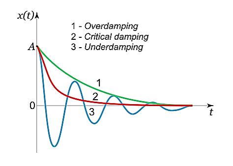
Figure 10: Damping Graph
Case 2. Critical Damping: β=ω0
You may have observed that on hitting an isolated road bump, a car bounces up and down and the occupants feel uncomfortable. To minimise this discomfort, the bouncing caused by the road bumps must be damped very rapidly and the automobile is restored to equilibrium quickly. For this we use critically damped shock absorbers. Critical damping is also useful in recording instruments such as a galvanometer (pointer type as well as suspended coil type) which experience sudden impulses. We require the pointer to move to the correct position in minimum time and stay there without executing oscillations. Similarly, a ballistic galvanometer coil is required to return to zero displacement immediately.
In the limiting case when β=ω0, the roots of the characteristic equation are real and coincide:
λ1=λ2=−β=−ω0.
Here the solution is given by the formula
x(t)=(C1t+C2)
In this mode, the value of x(t) may even increase at the beginning of the process because of the linear factor C1t+C2. But in the end the deflection x(t) decreases rapidly due to the exponential decay with a characteristic time τ=2π/ω0.
Note that in this critical mode the relaxation occurs faster than in the case of the aperiodic damping (Case 1). Indeed, in this mode the relaxation time will be determined by the smaller (in absolute value) root λ1, and will be given by the formula

The function Φ(β/ω0) included in this expression is monotonically increasing. It is always greater than or equal to 1, as shown in Figure 11

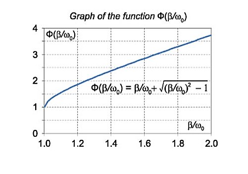
Figure 11: Graph of function Φ( )
)
In the critical case (Case 2) the ratio βω0 is 1, and βω0>1 in the case of the aperiodic damping (Case 1). Therefore for the aperiodic damping mode, we can write
τ= Φ(
Φ( ) >
) > 
Thus, the critical damping mode provides the fastest possible return of the system to equilibrium. This is often used, for example, in door closing mechanisms.
Case 3. Underdamping or Light Damping β<ω0
Here the roots of the characteristic equation are complex conjugate:
λ1,2 =−β±i√
The general solution of the differential equation is oscillatory in nature and can be written as
x(t)=e−βt[C1cos(ω1t)+C2sin(ω1t)]
Where the oscillation frequency ω1 is equal to
ω1= 
The resulting formula can be written in a somewhat different form:
x(t)=Ae−βtcos(ω1t+φ0),
Where φ0 is the initial phase of the oscillations and Acosφ0 is the initial amplitude of the oscillations. We see that classical damped oscillations occur in this mode. Here the oscillation frequency ω1 is less than the harmonic frequency ω0, and the oscillation amplitude decreases exponentially with e−βt.
Key Takeaways
- Damped oscillations refer to oscillations where the oscillating object loses its energy to the surroundings.
- When resistance to motion is.very strong, the system is said to be heavily damped. β>ω0
- The critical damping mode provides the fastest possible return of the system to equilibrium. . β = ω0
- In Case of Underdamping or Light Damping classical damped oscillations occur β<ω0
We know that in the presence of damping the amplitude of oscillation decreases with the passage of time. This means that energy is dissipated in overcoming resistance to motion. We know that, the total energy of a harmonic oscillator is made up of kinetic and potential components. We can still use the same definition and write
E(t) = K.E. + P.E.
=  m (
m ( )2+
)2+  kx2
kx2
Where ( ) denotes instantaneous velocity. For a weakly damped harmonic oscillator, the instantaneous displacement is given by
x(t) = a0 exp(-bt) cos (ωdt +ϕ)
By differentiating it with respect to time, we get instantaneous velocity:
 = v = a0 exp(-bt) [bcos (ωdt +ϕ) +ωd sin (ωdt +ϕ)]
Hence, kinetic energy of the oscillator is
K.E. =  m (
m ( )2 =
)2 =  m a02 exp(-2bt) [bcos (ωdt +ϕ) +ωd sin (ωdt +ϕ)]2
=  m a02 exp(-2bt) [b2cos2 (ωdt +ϕ) +ω2d sin2 (ωdt +ϕ) + b ωd 2sin (ωdt +ϕ)]
Similarly, the potential energy of the oscillator is
U =P.E.=  kx2 =
kx2 = 
Since k = 
On substituting for x, we get
U =  =
=  a02 exp(-2bt) [cos (ωdt +ϕ)]2
Hence, the total energy of the oscillator at any time t is given by
E(t) =  m a02 exp(-2bt) [(b2+ ω2o) cos2 (ωdt +ϕ) +ω2d sin2 (ωdt +ϕ) + b ωd 2sin (ωdt +ϕ)]
When damping is small, the amplitude of oscillation does not change much over one oscillation. So we may take the factor exp (-2bt) as essentially constant. Further, since < sin2 (ωdt +ϕ) > = < cos2 (ωdt +ϕ) > =  and <sin (ωdt +ϕ)> = 0, the energy of a weakly damped oscillator when averaged-over one cycle is given by
<E> = <  m a02 exp(-2bt) [(b2+ ω2o) cos2 (ωdt +ϕ) +ω2d sin2 (ωdt +ϕ) + b ωd 2sin (ωdt +ϕ)]>
<E> =  m a02 exp(-2bt) [
 +
+  ]
]
<E> =  m a02
m a02  exp(-2bt)
E0 = m a02
m a02  is the total energy of an undamped oscillator. Hence, we can write <E> = Eo exp (- 2bt)
This shows that the average energy of a weakly damped oscillator decreases exponentially with time. This is illustrated in Figure 11. You will also observe that the rate of decay of energy depends on the value of b; larger the value of b, faster will be the decay.
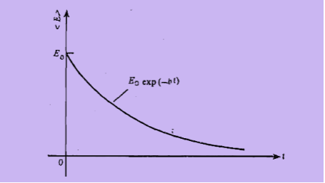
Figure 12: Energy decay in a damped harmonic oscillator
Key Takeaways
- In the presence of damping the amplitude of oscillation decreases with the passage of time. This means that energy is dissipated in overcoming resistance to motion.
- The total energy of a harmonic oscillator is made up of kinetic and potential components.
- E0 =
 m a02
m a02  is the total energy of an undamped oscillator.
 - The average energy <E> = Eo exp (- 2bt) of a weakly damped oscillator decreases exponentially with time.
The energy loss rate of a weakly damped (i.e., ν ) harmonic oscillator is conveniently characterized in terms of a parameter, Qf, which is known as the quality factor. This quantity is defined to be 2π times the energy stored in the oscillator, divided by the energy lost in a single oscillation period. If the oscillator is weakly damped then the energy lost per period is relatively small, and Qf is therefore much larger than unity. Roughly speaking, Qf is the number of oscillations that the oscillator typically completes, after being set in motion, before its amplitude decays to a negligible value. Let us find an expression for Qf.
As we have seen, the motion of a weakly damped harmonic oscillator is specified by
 (1)
(1)
It follows that
 | (2) |
The energy lost during a single oscillation period is


![$\displaystyle = m \nu a^{2}\int_{\phi/\omega_1}^{(2\pi+\phi)/\omega_1}{\rm e}...
...{2} \cos(\omega_1 t-\phi) + \omega_1 \sin(\omega_1 t-\phi)\right]^{ 2} dt.$](https://glossaread-contain.s3.ap-south-1.amazonaws.com/epub/1642993836_1954207.png) (3)
(3)
In the weakly damped limit, ν , the exponential factor is approximately unity in the interval t= ϕ/ω1 to (2π+ ϕ)/ ω1 , so that
 (4)
(4)
Where θ = ω1t- ϕ . Thus,
 (5)
(5)
because, as is readily demonstrated,
  |
| (6) |
  |
| (7) |
The energy stored in the oscillator (at t=0 ) is [cf., Equation (16)]
 (8)
(8)
Hence, we obtain
 (9)
(9)
Yet another way of expressing the damping effect is by means of the rate of decay of energy.
We note that the average energy of a weakly damped oscillator decays to Eoe-1 in time t =  =
=  seconds. If ωd is its angular frequency, then in this time the oscillator will vibrate through ωd m/
  radians. The number of radians through which a weakly damped system oscillates as its average energy decays to Eoe-1 is a measure of the quality factor Q.
You will note that Q is only a number and has no dimensions. In general,  is small so that Q is very large. A tuning fork has Q of a thousand or so, whereas a rubber band exhibits a much lower (-10) Q. This is due to the internal friction generated by the coiling of the long chain of molecules in a rubber band. An undamped oscillator ' (
 = 0) has an infinite quality factor.
For a weakly damped mechanical oscillator, the quality factor can be expressed in term; of the spring factor and damping constant. For weak damping,
ωd  ωd -
ωd - 
Q = 
That is, the quality factor of a weakly damped oscillator is directly proportional to the square root of k and inversely proportional to .
.
In a more physically meaningful form
Q =  =
= 


= 


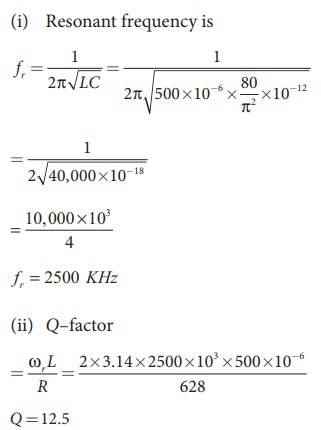
Example: A 500 μH inductor, 80/π2 pF capacitor and a 628 Ω resistor are connected to form a series RLC circuit. Calculate the resonant frequency and Q-factor of this circuit at resonance.
Solution
L=500×10-6H; C = 80/π2 ×10−12 F; R = 628Ω
Key Takeaways
- The energy loss rate of a weakly damped (i.e., ν
 ) harmonic oscillator is conveniently characterized in terms of a parameter, Qf, which is known as the quality factor
 - Qf is the number of oscillations that the oscillator typically completes, after being set in motion, before its amplitude decays to a negligible value.
- It is given by Q =


MECHANICAL OSCILLATORS
The simple harmonic oscillator describes many physical systems throughout the world, but early studies of physics usually only consider ideal situations that do not involve friction.
In the real world, however, frictional forces – such as air resistance – will slow, or dampen, the motion of an object. Sometimes, these dampening forces are strong enough to return an object to equilibrium over time.
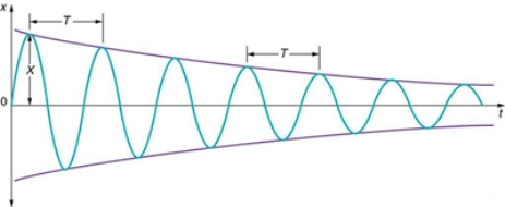
Figure 13: The position against time of our object moving in simple harmonic motion.
Illustrating the position against time of our object moving in simple harmonic motion. We see that for small damping, the amplitude of our motion slowly decreases over time.
The simplest and most commonly seen case occurs when the frictional force is proportional to an object’s velocity. Note that other cases exist which may lead to nonlinear equations which go beyond the scope of this example.
Consider an object of mass m attached to a spring of constant k. Let the damping force be proportional to the mass’ velocity by a proportionality constant, b, called the vicious damping coefficient. We can describe this situation using Newton’s second law, which leads to a second order, linear, homogeneous, ordinary differential equation. We simply add a term describing the damping force to our already familiar equation describing a simple harmonic oscillator to describe the general case of damped harmonic motion.
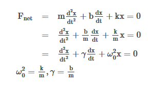
This notation uses d2x/dt2, the acceleration of our object, dx/dt, the velocity of our object, ω0, undamped angular frequency of oscillation, and  , which we can call the damping ratio.
We solve this differential equation for our equation of motion of the system, x(t). We assume a solution in the form of an exponential, where a is a constant value which we will solve for.
x(t)=eat
Plugging this into the differential equation we find that there are three results for a, which will dictate the motion of our system. We can solve for a by using the quadratic equation.
Fnet=a2x+γax+ x = 0 =
a=
The physical situation has three possible results depending on the value of a, which depends on the value of what is under our radical. This expression can be positive, negative, or equal to zero which will result in overdamping, underdamping, and critical damping, respectively.
 >
> is the Over Damped case. In this case, the system returns to equilibrium by exponentially decaying towards zero. The system will not pass the equilibrium position more than once.
 is the Under Damped case. In this case, the system oscillates as it slowly returns to equilibrium and the amplitude decreases over time. Figure 13 depicts an underdamped case.
 is the Critically Damped case. In this case, the system returns to equilibrium very quickly without oscillating and without passing the equilibrium position at all.
ELECTRICAL OSCILLATORS
Electric oscillations can be excited in a circuit containing resistance R, inductance L and capacitance C. The series RLC-circuit is shown in Figure 14
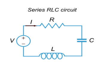
Figure 14: Series RLC circuit
We derive the differential equation describing the current change in a series RLC circuit.
The voltages VR,VC,VL, respectively, on the resistor R, capacitor C and inductor L are given by
VR(t)=RI(t), VC(t)=
 VL(t)=L
  .
.
It follows from the Kirchhoff’s voltage law (KVL) that
VR(t)+VC(t)+VL(t)=E(t),
Where E(t) is the electromotive force (emf) of the power supply.
In the case of constant emf E, we obtain the following differential equation after substituting the expressions for VR, VC,VL and differentiation:
 +
+ I(t) =0
If we denote 2β= ,
,  =
=  , the equation can be written as
 +
+ I(t) =0
This differential equation coincides with the equation describing the damped oscillations of a mass on a spring. Hence, damped oscillations can also occur in series RLC-circuits with certain values of the parameters.
The second order differential equation describing the damped oscillations in a series RLC-circuit we got above can be written as
 +
+ I(t) =0
The corresponding characteristic equation has the form
λ2+ λ+
λ+ =0.
=0.
Its roots are calculated by the formulas:
λ 1,2 =  =
=  =
= 
Where the value of β = is called the damping coefficient, and ω0 is the resonant frequency of the circuit.
Depending on the values of R,L,C there may be three options.
Case 1. Overdamping: R2>
In this case, both roots of the characteristic equation λ1 and λ2 and real, distinct and negative. The general solution of the differential equation is given by
I(t)=C1 +C2
+C2
In this mode, the current decreases monotonically approaching zero
Case 2. Critical Damping: R2= 
This mode can be called boundary or critical. Here, both roots of the characteristic equation are equal, real and negative. The general solution is expressed by the function
I(t)=(C1t+C2)e−βt=)=(C1t+C2)exp(− t)
t)
At the beginning of the process, the current may even increase, but then it quickly decreases exponentially.
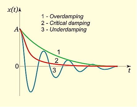
Figure 15: Damping graph
Case 3. Underdamping: R2< 
In this case, the roots of the characteristic equation are complex conjugate, which leads to damped oscillations in the circuit. The change of current is given by
I(t)=e−βt(Acosωt+Bsinωt),
Where the value of β=  is as above the damping factor, ω =
  is the frequency of oscillation, A,B are constants of integration, depending on initial conditions. Note that the frequency ω of damped oscillations is less than the resonant frequency ω0 of the circuit. The typical shape of the curve I(t) in this mode is also shown in Figure above.
Key Takeaways
- In the real world, however, frictional forces – such as air resistance – will slow, or dampen, the motion of an object.
- Sometimes, these dampening forces are strong enough to return an object to equilibrium over time.
 is damping ratio. For mechanical system
  >
> is the Over Damped case.
  is the Under Damped case.
 is the Critically Damped case.
 - For Electric oscillator depending on the values of R,L,C there may be three options. Overdamping: R2>
 , Critical Damping: R2=
  and Underdamping: R2<
Mechanical Impedance can be calculated as
The force required to produce unit velocity is called the mechanical impedance of the oscillator.
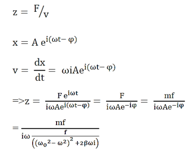
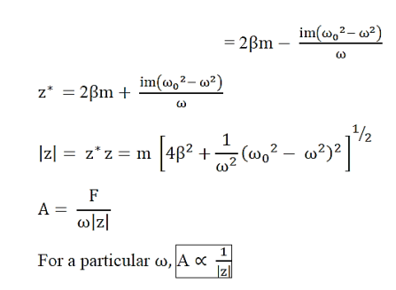
In case of electrical oscillator the impedance Z is given as follow
If the resonant circuit includes a generator with periodically varying emf, the forced oscillations arise in the system. If the emf E of the source varies according to the law
E(t)=E0cosωt
Then the differential equation of forced oscillations in series RLC-circuit can be written as
 +
+ q(t) =
 E0cosωt
Where q the charge of the capacitor ,2β= ,
,  =
=  , the equation can be written as
 +
+ q(t) =
  E0cosωt
This equation is analogous to the equation of forced oscillations of a spring pendulum, discussed on the page Mechanical Oscillations. Its general solution is the sum of two components: the general solution of the associated homogeneous equation and a particular solution of the nonhomogeneous equation. The first component describes the decaying transient process, after which the behavior of the system depends only on the external driving force. The forced oscillations will occur according to the law
Upon solving these we get the following results
The amplitude of the current I0

And the phase shift θ are given by

The quantity

Is called the impedance, or impedance of the circuit. It consists of an ohmic resistance R and a reactance ωL−1/ωC.
Example:: Find the impedance of a series RLC circuit if the inductive reactance, capacitive reactance and resistance are 184 Ω, 144 Ω and 30 Ω respectively. Also calculate the phase angle between voltage and current.
Solution
XL = 184 Ω; XC = 144 Ω
R = 30 Ω
(i ) The impedance is
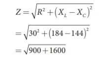
Impedance, Z = 50 Ω
(ii) Phase angle is
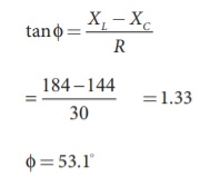
φ = 53.1
Key Takeaways
- Mechanical Impedance can be calculated as the force required to produce unit velocity is called the mechanical impedance of the oscillator. It is given by

- In case of electrical oscillator the impedance Z is given as

- It consists of an ohmic resistance R and a reactance ωL−1/ωC.
FORCED OSCILLATION
The oscillation of a oscillator is said to be forced oscillator or driven oscillation if the oscillator is subjected to external periodic force.
If an external periodic sinusoidal force Fcosωt acts on a damped oscillator, its equation of motion is written as,
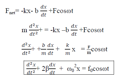 …………(1)
Where β= b/2m,  = k/m and f0 = F/m , and β and
  respectively called as damping coefficient, natural frequency.
Equation (1) is also represented as

 = f0cosωt
Equation (1) represents the general equation of forced oscillation.
Equation (1) is a non-homogenous differential equation with constant co-efficient. For weak damping ( >β 2) , the general equation contains,
x(t) = xc(t) + xp(t)
Where xc(t) is called complementary solution and its value is
 …………(2)
Now xp(t) is called the particular integral part.
Let us choose
xp(t) = P cos (ωt-δ)
 (t)= -Pωsin(ωt-δ)
 (t)=-Pω2cos(ωt-δ) ……………(3)
Putting xp(t) ,  (t),
(t),  (t) in equation (1) we get


Now, comparing the coefficient of cos(ωt-δ) and sin (ωt-δ) on both sides,
( -ω2)P = f0cosδ ……………(4)
2βPω = f0sinδ ……………(5)
Squaring and adding eqn (4) & (5)
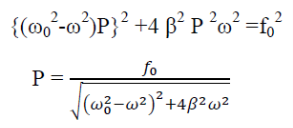 ……….(6)
Now dividing equation (5) by (6)


This is steady state solution. Now
x(t) = xc(t) + xp(t)

STEADY STATE BEHAVIOUR
Frequency:-The Oscillator oscillates with the same frequency as that of the periodic force.
ω0 and ω are very close to each other then beats will be produced and these beats are transient as it lasts as long as the steady state lasts. The duration between transient beats is determined by the damping coefficient β.
PHASE: The phase difference δ between the oscillator and the driving force or between the displacement and driving is

This shows that there is a delay between the action of the driving force and response of the oscillator.
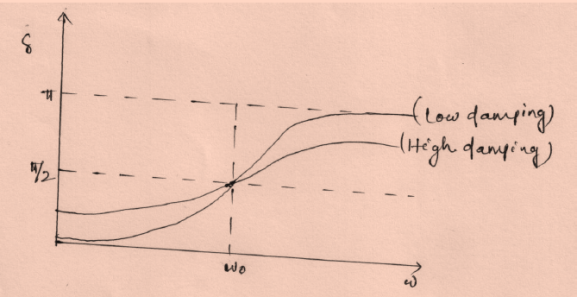
Figure 16: Phase variation
(In the above figure fQ= ω0 and fp= ω)
At ω=ω0, φ =π/2, the displacement of the oscillator lags behind the driving force by π/2.
At ω<<ω0 then δ=0→ δ=0
For ω>> ω0 then δ =-2p/ ω → -0= π
AMPLITUDE: The amplitude of driven oscillator, in the steady state , is given by

It depends upon ( -ω2). If it is very small, then the amplitude of forced oscillation increases.
Case-1: At very high driving force i.e ω>>ω0 and damping is small (β is small) or (β→0)
A = 
A =  =
= 
Amplitude is inversely proportional to the mass of the oscillator & hence the motion is mass controlled motion.
Case-2: At very low driving force (ω<<ω0) and damping is small ( β→0),
i.e.  -ω2 =
-ω2 = 
A = 
A =  =
= 
So, when the low driving force is applied to oscillator, the amplitude remains almost constant for low damping. The amplitude of the forced oscillator in the region ω<<ω0 and β< ω0 is inversely proportional to the stiffness constant (k) and hence motion is called the stiffness controlled motion.
Case:-3 (Resistance controlled motion)
When angular frequency of driving force=natural frequency of oscillator i.e.(ω=ω0)
A =  =
= 
A=f/bω=f/bω0
Key Takeaways
- The oscillation of a oscillator is said to be forced oscillator or driven oscillation if the oscillator is subjected to external periodic force.
- The Oscillator oscillates with the same frequency as that of the periodic force. ω0 and ω are very close to each other, then beats will be produced.
- The phenomena of producing oscillatory motion in a system by the influence of an external periodic force having the same frequency as that of natural frequency of the system is called Resonance.
In order to maintain the steady state oscillations of the system the driving force must replace the energy lost in each cycle because of the presence of the resistance.
We shall now derive the most important result that: ‘in the steady state the amplitude and phase of a driven oscillator adjust themselves so that the average power supplied by the driving force just equals that being dissipated by the frictional force’.
The instantaneous power P supplied is equal to the product of the instantaneous driving force and the instantaneous velocity; that is,
i). Power absorption:
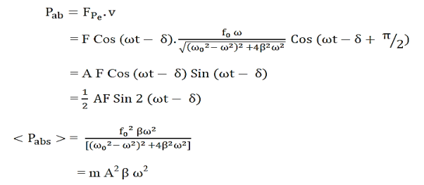
Power absorbed is maximum when ω=ω0

Ii). Power dissipation:
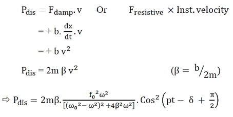

Thus in the steady state of forced vibration, the average rate of power supplied by the forcing system is equal to the average of work done by the forced system against the damping force.
Key Takeaways
- The instantaneous power P supplied is equal to the product of the instantaneous driving force and the instantaneous velocity.
- Power absorption is given by <Pabs> = m
 A2 ω2
A2 ω2 - Power dissipation is given by <Pdis> = m
 A2 ω2
A2 ω2
References
1. H. J. Pain, “The physics of vibrations and waves”, Wiley, 2006
2. I. G. Main, “Vibrations and waves in physics’, 3rd Edn, Cambridge University Press, 2018.