UNIT 4
WAVE OPTICS
Huygens' Principle
In 1678 Huygens proposed a model where each point on a wavefront may be regarded as a source of waves expanding from that point.
Every point on a wavefront is a source of wavelets that spread out in the forward direction at the same speed as the wave itself. The new wavefront is a line tangent to all of the wavelets.
So Huygens’s Principle states that every point on a wavefront is a source of wavelets, which spread forward at the same speed.
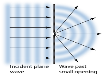
Figure 1: Huygens' Principle
The expanding waves may be demonstrated in a ripple tank by sending plane waves toward a barrier with a small opening. If waves approaching a beach strike a barrier with a small opening, the waves may be seen to expand from the opening.
Huygens-Fresnel Theory:
According to Huygens’s wave theory of light, each progressive wave produces secondary waves, the envelope of which forms the secondary wave front.
In figure 2 (a). S is a source of monochromatic light and MN is a small aperture. XY is the screen placed in the path of light. AB is the illuminated portion of the screen and above A and below B is the region of the geometrical shadow. Considering MN as the primary wave front. According to Huygens’s construction, if secondary wave fronts are drawn, one would expect encroachment of light in the geometrical shadow. Thus, the shadows formed by small obstacles are not sharp. This bending of light round the edges of an obstacle or the encroachment of light within the geometrical shadow is known as diffraction. Similarly, if an opaque obstacle MN is placed in the path of light [Figure 2 (b)], there should be illumination in the geometrical shadow region AB also. But the illumination in the geometrical shadow of an obstacle is not commonly observed because the light sources are not point sources and secondly the obstacles used are of very large size compared to the wavelength of light. If a shadow of an obstacle is cast by an extended source, say a frosted electric bulb, light from every point on the surface of the bulb forms its own diffraction pattern (bright and dark diffraction bands) and these overlap such that no single pattern can be identified. The term diffraction is referred to such problems in which one considers the resultant effect produced by a limited portion of a wave front.
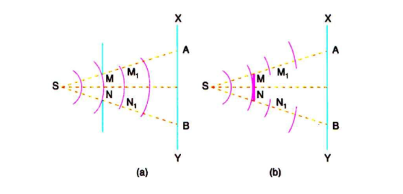
Figure 2: Huygens’s wave theory of light,
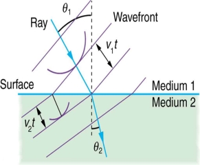
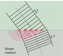
Huygens' principle provides a convenient way to visualize refraction. If points on the wavefront at the boundary of a different medium serve as sources for the propagating light, one can see why the direction of the light propagation changes.
The law of refraction can be explained by applying Huygens’s principle to a wavefront passing from one medium to another (see Figure 3). Each wavelet in the figure was emitted when the wavefront crossed the interface between the media. Since the speed of light is smaller in the second medium, the waves do not travel as far in a given time, and the new wavefront changes direction as shown. This explains why a ray changes direction to become closer to the perpendicular when light slows down.
 |  |
(a) | (b) |
Figure 3: Law of refraction by Huygens’s principle
If we pass light through smaller openings, often called slits, we can use Huygens’s principle to see that light bends as sound does. The bending of a wave around the edges of an opening or an obstacle is called diffraction.
Diffraction is a wave characteristic and occurs for all types of waves. If diffraction is observed for some phenomenon, it is evidence that the phenomenon is a wave. Thus the horizontal diffraction of the laser beam after it passes through slits is evidence that light is a wave.
Diffraction phenomena are part of our common experience. The luminous border that surrounds the profile of a mountain just before the sun rises behind it, the light streaks that one sees while looking at a strong source of light with half shut eyes and the coloured spectra (arranged in the form of a cross) that one sees while viewing a distant source of light through a fine piece of cloth are all examples of diffraction effects. Augustine Jean Fresnel in 1815, combined in a striking manner Huygens’ wavelet with the principle of interference and could satisfactorily explain the bending of light round obstacles and also the rectilinear propagation of light.
Key takeaways
- Huygens’s Principle states that every point on a wavefront is a source of wavelets, which spread forward at the same speed.
- According to Huygens’s wave theory of light, each progressive wave produces secondary waves, the envelope of which forms the secondary wave front.
- Huygens' principle provides a convenient way to visualize refraction.
- Huygens’s principle to see that light bends as sound does. The bending of a wave around the edges of an opening or an obstacle is called diffraction.
The principle of superposition says:
When two or more waves cross at a point, the displacement at that point is equal to the sum of the displacements of the individual waves.
The individual wave displacements may be positive or negative. If the displacements are vectors, then the sum is calculated by vector addition.
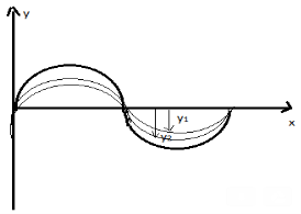
Figure 4: Principle of superposition
Superposition is an important idea that can explain phenomena including interference, diffraction and standing waves. It works for any type of wave (sound waves, water surface waves, electromagnetic waves...) but only works under certain conditions, which we describe below.
When the waves pass beyond a point of intersection, they separate out again and are unaffected.
The principle of superposition can be applied to any type of wave providing that:
- The waves being superposed are of the same type (e.g. All are electromagnetic waves)
- The medium that the waves are propagating through behaves linearly, i.e. when part of the medium has twice the displacement then it has twice the restoring force. This is usually true when the amplitudes are relatively small. For example, for waves on water, it is a good approximation for small ripples on a pond whose amplitude is much smaller than their wavelength.
If the waves are also coherent - i.e. if they all have the same frequency and a constant phase difference - then the superposition resembles another wave with the same frequency.
Considering two waves, travelling simultaneously along the same stretched string in opposite directions as shown in the figure above. We can see images of waveforms in the string at each instant of time. It is observed that the net displacement of any element of the string at a given time is the algebraic sum of the displacements due to each wave.
Let us say two waves are travelling alone and the displacements of any element of these two waves can be represented by y1(x, t) and y2(x, t). When these two waves overlap, the resultant displacement can be given as y(x,t).
Mathematically, y (x, t) = y1(x, t) + y2(x, t)
As per the principle of superposition, we can add the overlapped waves algebraically to produce a resultant wave. Let us say the wave functions of the moving waves are
y1 = f1(x–vt),
y2 = f2(x–vt)
……….
yn = fn (x–vt)
Then the wave function describing the disturbance in the medium can be described as
y = f1(x – vt)+ f2(x – vt)+ …+ fn(x – vt)
Or, y= 
Let us consider a wave travelling along a stretched string given by,
y1(x,t) = A sin (kx – ωt)
And another wave, shifted from the first by a phase φ, given as
y2(x, t) = A sin (kx – ωt + ϕ)
From the equations we can see that both the waves have the same angular frequency, same angular wave number k, hence the same wavelength and the same amplitude A.
Now, applying the superposition principle, the resultant wave is the algebraic sum of the two constituent waves and has displacement
y(x, t) = A sin (kx – ωt) + A sin (kx – ωt + ϕ)
As, sin A + sin B = 2sin (A+B)/2 .cos (A−B)/2
The above equation can be written as,
y(x, t) = [2A cos ϕ /2 ] sin (kx − ωt + ϕ /2)
The resultant wave is a sinusoidal wave, travelling in the positive X direction, where the phase angle is half of the phase difference of the individual waves and the amplitude as [2cos ϕ /2] times the amplitudes of the original waves.
Hence, the superposition of waves can lead to the following three effects:
- Whenever two waves having the same frequency travel with the same speed along the same direction in a specific medium, then they superpose and create an effect known as the interference of waves.
- In a situation where two waves having similar frequencies move with the same speed along opposite directions in a specific medium, then they superpose to produce stationary waves.
- Finally, when two waves having slightly varying frequencies travel with the same speed along the same direction in a specific medium, they superpose to produce beats.
THEORY OF INTERFERENCE FRINGES
INTERFERENCE
Interference in light waves occurs whenever two or more waves overlap at a given point.
TYPES OF INTERFERENCE
Interference of light waves can be either constructive interference or destructive interference.
- Constructive Interference: Constructive interference takes place when the crest of one wave falls on the crest of another wave such that the amplitude is maximum. These waves will have the same displacement and are in the same phase.
- Destructive Interference: In destructive interference the crest of one wave falls on the trough of another wave such that the amplitude is minimum. The displacement and phase of these waves are not the same.
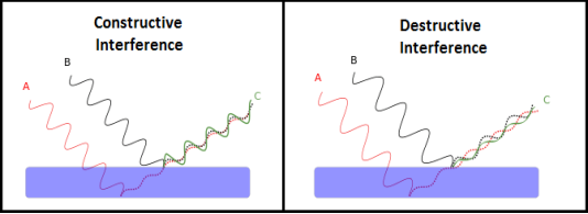
Figure 5: Types of interference
We know that the superposition of two mechanical waves can be constructive or destructive. In constructive interference, the amplitude of the resultant wave at a given position or time is greater than that of either individual wave, whereas in destructive interference, the resultant amplitude is less than that of either individual wave.
Light waves also interfere with each other. Fundamentally, all interference associated with light waves arises when the electromagnetic fields that constitute the individual waves combine.
If two light bulbs are placed side by side, no interference effects are observed because the light waves from one bulb are emitted independently of those from the other bulb. The emissions from the two light bulbs do not maintain a constant phase relationship with each other over time. Light waves from an ordinary source such as a light bulb undergo random phase changes in time intervals less than a nanosecond.
Therefore, the conditions for constructive interference, destructive interference, or some intermediate state are maintained only for such short time intervals. Because the eye cannot follow such rapid changes, no interference effects are observed. Such light sources are said to be incoherent.
Two sources are said to be coherent when the waves emitted from them have the same frequency and constant phase difference.
Interference from such waves happen all the time, the randomly phased light waves constantly produce bright and dark fringes at every point. But, we cannot see them since they occur randomly. A point that has a dark fringe at one moment may have a bright fringe at the next moment. This cancels out the effect of the interference effect, and we see only an average brightness value. The interference is not said to be sustained since we cannot observe it.
Definition:- A predictable correlation of the amplitude and phase at any one point with other point is called coherence.
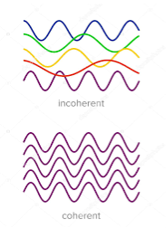
Figure 6: Incoherence and coherence
COHERENT SOURCES
Two waves are said to be coherent, the waves must have
In case of convectional light, the property of coherence exhibits between a source and its virtual source where as in case of laser the property coherence exists between any two of more light waves.
There are two types of coherence
i) Temporal coherence
Ii) Spatial coherence
TEMPORAL COHERENCE (OR LONGITUDINAL COHERENCE):-
The predictable correlation of amplitude and phase at one point on the wave train w .r. t another point on the same wave train, then the wave is said to be temporal coherence
To understand this, let us consider two points P1 and P2 on the same wave train, which is continuous as in shown in figure.

Figure 7: Wave train
Suppose the phase and amplitude at any one point is known, then we can easily calculate the amplitude and phase for any other point on the same wave train by using the wave equation
y= a sin ( (ct-x))
Where ‘a’ is the amplitude of the wave and ‘x’ is the displacement of the wave at any instant of time‘t’.
SPATIAL COHERENCE (OR TRANSVERSE COHERENCE)
The predictable correlation of amplitude and phase at one point on the wave train w. r .t another point on a second wave, then the waves are said to be spatial coherence (or transverse coherence)
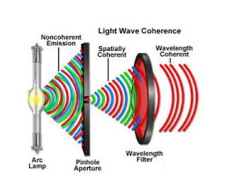
Figure 8: Spatial coherence
CONDITIONS FOR SUSTAINED INTERFERENCE
In a sustained interference pattern, the position of maximum and minimum intensity regions remains constant with time. To obtain the sustained interference, the following conditions are required:
- The sources must be coherent, that is, they must maintain a constant phase with respect to each other.
- The two light sources must emit continuous waves of the same wavelength and having the same time period.
- The distance between the two sources of light must be small. This gives large fringe width so that the fringes are separately visible.
- The sources should be monochromatic, that is, of a single wavelength.
- The two light sources must emit waves in nearly the same direction.
- Light source must be a point source.
- The distance between the two sources and screen must be large. This gives again large fringe width so that the fringes are separately visible.
The phenomenon of interference may be grouped into two categories:
- Division of Wavefront
- Division of Amplitude
Division of Wavefront
Under this category, the coherent sources are obtained by dividing the wavefront, originating from a common source, by employing mirrors, biprisms or lenses. This class of interference requires essentially a point source or a narrow slit source. The instruments used to obtain interference by division of wavefront are the Fresnel biprism, Fresnel mirrors, Lloyd's mirror, lasers, etc.
Some of the standard arrangements used to observe two-wave interference by division of the wavefront are shown in Figure.
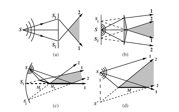
Figure 9: Two-wave interference; (a) Young’s two-slit arrangement, (b) Fresnel’s
Biprism, (c) Fresnel’s two mirrors, (d) Loyd’s mirror
In Figure 9(a) The narrow slits S1 and S2 in Young’s double slit arrangement intercept portions of the spherical wavefront and act as real mutually coherent point sources, diffracting light in the forward direction. Interference among the diffracted waves can be observed anywhere in the region of overlap (shaded portion) behind the plane of the slits. Historically, the interference produced in Young’s double slit experiment was not accepted as a conclusive proof of the wave nature of light because it was thought that the fringes in Young’s experiment could arise due to some unexplained interaction of light with the edges of the slits.
In Figure 9(b) Fresnel’s biprisms arrangement, however, established the wave nature of light beyond any doubt. Fresnel’s biprism consists of two small angle (a few degrees) prisms in a manner that the incident spherical wavefront is split by the two prisms. The split wavefronts travel in different directions, eventually overlap and produce interference. S1 and S2 act as virtual but mutually coherent point sources.
Figure 9(c) shows the two-mirror arrangement, also devised by Fresnel. Here, the portions of the spherical wavefront reflected by the two mirrors overlap to produce interference. The source images S1 and S2, formed by the two mirrors, are virtual but mutually coherent.
In Figure 9(d) shows Lloyd’s single mirror arrangement, interference is produced by the portion of the wavefront reflected by the mirror and the portion which propagates directly to the region of superposition. In this case, the point source S and its virtual image S’ act as mutually coherent point sources.
Division of Amplitude
In this method, the amplitude of the incident beam is divided into two or more parts either by partial reflection or refraction. Thus we have coherent beams produced by division of amplitude. These beams travel different paths and are finally brought together to produce interference. The effects resulting from the superposition of two beams are referred to as two beam interference and those resulting from superposition of more than two beams are referred to as multiple beam interference. The interference in thin films, Newton's rings, and Michelson's interferometer are examples of two beam interference and Fabry-Perot's interferometer is an example of multiple beam interference.
In case of division by wavefront, we considered two-wave interference when different portions of the wavefront are made to propagate in different directions and then recombined. Now, we discuss two-wave interference when a quasi-monochromatic wave is incident on a thin transparent film as shown in Figure. Here we will discuss interference by division of amplitude.
The wave is partly reflected and partly transmitted at each interface. Amplitudes of successively reflected and transmitted waves diminish rapidly for films of low reflectivity. The amplitude transmission coefficient for passage of the wave from the medium of refractive index n1 to the medium of refractive index n2 is t and t’ is the corresponding amplitude transmission coefficient for passage in the reverse direction.
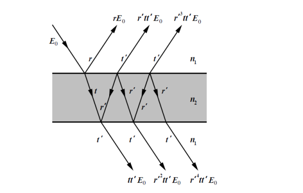
Figure 10: Reflection and transmission across a thin film.
The amplitude reflection coefficients for the external and internal reflections are r and r’=−r, respectively. For sufficiently small r (r2 <1), only two waves need to be considered in reflection as well as in transmission, leading to two-wave interference. The amplitudes of the first two waves in reflection are comparable, but those in transmission differ considerably.
As a result, interference fringes in reflected light have higher visibility than those in transmitted light.
Key takeaways
- The principle of superposition says that when two or more waves cross at a point, the displacement at that point is equal to the sum of the displacements of the individual waves.
- Interference in light waves occurs whenever two or more waves overlap at a given point.
- Interference of light waves can be either constructive interference or destructive interference.
- A predictable correlation of the amplitude and phase at any one point with other point is called coherence. There are two types of coherence; Temporal coherence and Spatial coherence
- The phenomenon of interference may be grouped into two categories: Division of Wavefront and Division of Amplitude
- The instruments used to obtain interference by division of wavefront are the Fresnel biprism, Fresnel mirrors, Lloyd's mirror, lasers, etc.
- The interference by division of amplitude is seen in thin films, Newton's rings, and Michelson's interferometer (examples of two beam interference) and Fabry-Perot's interferometer (example of multiple beam interference).
In 1801 Thomas performed double slit experiment. He gave evidence for the wave theory of light from double slit interference experiment.
Suppose monochromatic light of wavelength λ is allowed to pass through a slit S and two parallel slits S1 and S2 are placed at equidistant from S.
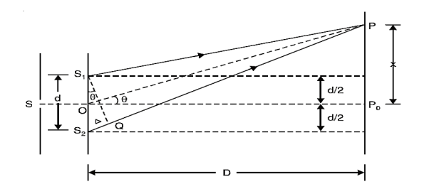
Figure 11: Young’s double slit experiment
The slits S1 and S2 act as coherent sources. Both these slits are of same width, they will emit waves or disturbances of equal amplitudes.
These disturbances are superimposed at P on the screen with a phase difference
 ...............(1)
Where Δ = S2P – S1P is the path difference.
Let us consider y1 is the displacement due to the waves coming from S1 and y2 is displacements due to the waves coming from S2,
Thus we have
 ...............(2)
Where a is the amplitude of both the waves. According to the principle of superposition, the resultant displacement y is given by
 ...............(3)
Where
 ...............(4)
And A is the amplitude of the resultant displacement. Thus,
 ...............(5)
The intensity I of the light at P is proportional to the square of the resultant amplitude.
 ............... (6)
Thus, we can write the equation (5) as
 ............... (7)
Where I0 is the intensity on the screen associated with light from one of the two slits, the other slit being temporarily covered.
For maximum intensity, δ = 0, 2π, 4π,... Or, path difference Δ = 0, λ, 2λ... ;
And for minimum intensity δ = π, 3π, 5π,... Or, Δ =  ,
,  ,
,  …
…
The point P0 on the screen is equidistant from S1 and S2. At P0, Δ = 0 and δ = 0. We have maximum intensity at P0.
From S1 we drop a perpendicular S1Q on S2P and suppose ∠ S2S1Q = θ,
Then Δ = d sin θ and δ =2π λ d sin θ,
Where d = S1S2 = separation between the coherent sources. Thus, the conditions for maxima and minima are
Maxima
 ............... (8)
Minima
 ............... (9)
Suppose the point P is at a distance x from P0 and D is the distance of the screen from the coherent sources. Then
 ............... (10)
D is the distance between slits and screen which is usually very large compared to d or x. Then, we can write
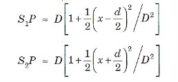 ............... (11)
The path difference Δ becomes
 ............... (12)
Where ∠POP0 = θ and  = tan θ.
The conditions for bright and dark fringes are
Bright fringes x =  , m = 0, +1, +2, ............... (13)
Dark fringes x =(  , m = 0, +1, +2, ............... (14)
At P0, m = 0, i.e., zeroth order bright fringe is formed at P0.
The distance between any two consecutive bright or dark fringes is known as fringe width and it is given by
β =(  -
-  =
=  ............... (15)
Thus, alternately dark and bright parallel fringes are formed on both sides of P0. The width of the bright fringe is equal to the width of the dark fringe.
The intensity at P is given by Eqn. (6). Since the amplitude a decreases with the increasing distance S1P, the intensity decreases with increasing x, and the intensity decreases with increasing D.
The intensity at bright points is 4I0 and at dark point it is zero. Here, the energy is transferred from the points of minimum intensity to the points of maximum intensity. The average value of cos2(δ/2) is 1/2. Therefore, the average intensity of the interference pattern is < I > = 2I0. Now, with two independent sources, each beam acts separately and contributes I0 and so without interference we would have a uniform intensity of 2I0.
Key Takeaways
- In 1801 Thomas performed double slit interference experiment. He gave evidence for the wave theory of light by this experiment.
- The intensity I of the light at P is given by

- The conditions for bright and dark fringes are given as : Bright fringes x =
 , m = 0, +1, +2, and Dark fringes x =(
  , m = 0, +1, +2,
 - The distance between any two consecutive bright or dark fringes is known as fringe width and it is given by β =(
 -
-  =
= 
Newton’s Rings are the circular interference pattern first discovered by physicist Sir Isaac Newton in 1704. It is cosists of concentric bright and dark rings with the point of contact of lens and the glass plate as centre,
The fringes obtained by interference of light waves by using the following arrangement
When a Plano convex lens with large radius of curvature is placed on a plane glass plate such that its curved surface faces the glass plate, a wedge air film (of gradually increasing thickness) is formed between the lens and the glass plate. The thickness of the air film is zero at the point of contact and gradually increases away from the point of contact.
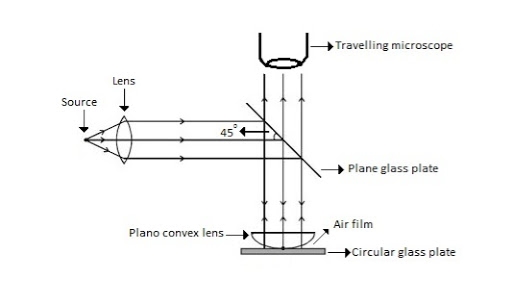
Figure 12: Newton Ring Assembly
If monochromatic (means light with single wavelength) light is allowed to fall normally on the lens from a source 'S', then two reflected rays R1 (reflected from upper surface of the film) and R2 (reflected from lower surface of the air film) interfere to produce circular interference pattern. This interference pattern has concentric alternate bright and dark rings around the point of contact. This pattern is observed through traveling microscope.
MATHEMATICAL ANALYSIS OF NEWTON’S RING
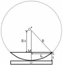
Figure 13: Mathematical analysis of newton’s ring
(OL)2 =(O’M)2-(ML)2 ……….(1)
R2=(R-t)2 +rn2
R2=R2 +t2-2Rt +rn2
Radius is large as compared to the thickness
So t2 is neglected as t2<< R2
R2=R2 +-2Rt +rn2
2Rt =rn2
Thickness of the film t =rn2 /2R ……….(2)
THEORY OF FRINGES:
The effective path difference between the two reflected rays R1 and R2 for a wedge shaped film from equation
∆ = 2μtcos(r+θ) +λ/2 ……….(3)
If the light is incident normally on the lens,
r = 0 and near to point of contact θ is small;
Therefore near point of contact, (r+θ) approaches to 0 and cos(r+θ)=cos0=1
Therefore
∆ = 2μt+λ/2 ……….(4)
Also At point of contact t = 0 therefore the effective path difference ∆ = λ/2
Which is odd multiple of λ/2 Therefore the Central fringe is dark.
BRIGHT FRINGE : CONDITION OF MAXIMA
For the condition of maxima the effective path difference
∆ = ±nλ
Using equation (4) ∆ = 2μt+λ/2 we have
2μt+λ/2= ±nλ
2μt = ± (2n-1)λ /2 ……….(5)
DIAMETER OF BRIGHT RINGS
We know by equation (2) t =rn2 /2R substitute in equation (5) we have
2μ (rn2 /2R) = ± (2n-1)λ /2
rn2 = ± (2n-1)λR /2μ
We know diameter D=2r and for nth fringe Dn=2rn
So we have Dn2=± 2(2n-1)λR /μ
Dn=
The medium enclosed between the lens and glass plate is if air therefore,  =1. The diameter of nth order bright fringe will be
D= n=0,1,2,3,4……. ……….(6)
The diameter of bright ring is proportional to square root of odd natural numbers
DARK FRINGE : CONDITION FOR MINIMA
For the condition of minima, The effective path difference
∆ =± (2n+1)λ /2
2μt+λ/2 =± (2n+1)λ /2
2μt= ±nλ ……….(7)
It is clear that for particular dark or bright fringe t should be constant.
Every fringe is the locus of points having equal thickness. Hence the fringes are circular in shape.
DIAMETER OF DARK RINGS
We know by equation (2) t =rn2 /2R substitute in equation (7) we have
2μ (rn2 /2R ) = nλ
rn2 = nλR/ μ
We know diameter D=2r and for nth fringe Dn=2rn
So we have Dn2= 4nλR/ μ
Dn= 
The medium enclosed between the lens and glass plate is if air therefore,  =1. The diameter of nth order bright fringe will be
Dn=  n=0,1,2,3,4……. ……….(8)
The diameter of dark ring is proportional to square root of natural numbers.
SPACING BETWEEN FRINGES
The Newton’s rings are not equally spaced because the diameter of ring does not increase in the same proportion as the order of ring and rings get closer and closer as ‘n’ increases.
For example the diameter of dark ring is given by Dn=  where n=0,1,2,3,4…….
D3 - D2 = -
-  = (
= ( -
- )
) = 0.635
D7 – D6 = -
-  = (
= ( -
- )
) = 0.392
D10– D9 = -
-  = (
= ( -
- )
) = 0.324
From above result we conclude that the fringe width reduces with increase in n.
APPLICATION OF NEWTON’S RING
- Determination of Wavelength of Light
The diameter of the nth order ring is calculated by subtracting the left and right side position of the microscope. As we know that the square of diameter of nth dark ring is

Therefore the square of diameter of (n+p)th ring is

Subtracting both the above equation
 ………...(9)
Therefore
 .............(10)
2. Determination of Refractive Index of liquid
In order to determine the refractive index of liquid the Newton’s ring experiment is first performed for the air medium and the difference in the square of the diameter of (n+p)th and nth dark ring is found as discussed above.
 ………….(11)
After this few drops of liquid of μ refractive index is placed on the glass plate. The plano-convex lens is then placed on the glass plate, as a result a film of liquid is formed between the lens and the plate.
The difference in the square of the diameter of (n+p)th and nth dark ring is again calculated in the same manner for the liquid medium.
 …..….(12)
Dividing equation 2.29 by 2.30, we get
 …….….(13)
3. Newton’s ring with white light
If the monochromatic source is replaced by the white light, dark and bright fringes are not produced. Because the diameter of the rings depends upon wavelength and it is proportional to the square root of wavelength.
If If the monochromatic source is replaced by the white light superposition of rings take place due to different wavelength. Few coloured rings are seen around dark centre later illumination is seen in the field of view. As shown in below figure.
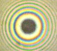
Figure 14: Newton’s ring with white light
Example: In a Newton’s rings experiment the diameter of the 15th ring was found to be 0.59 cm and that of the 5th ring is 0.336 cm. If the radius of curvature of the lens is 100 cm, find the wave length of the light.
Solution:
The given data are
Diameter of Newton’s 15th ring (D15) = 0.59 cm = 0.59×10⁻² m
Diameter of Newton’s 5th ring (D5) = 0.336 cm = 0.336 × 10⁻² m
Radius of curvature of lens (R) = 100 cm = 1 m
Wave length of light (λ) = ?
Here m is difference between rings = 15-5=10
λ = D2n+m - D2n / 4mR
λ = (0.59×10⁻² )2- (0.336 × 10⁻²)2 / 4 x 10 x 1
λ = 0.3481 x10⁻⁴ – 0.112896 x10⁻⁴ / 40
λ =0.00588 x 10⁻⁴ m
λ =5880 x 10-10 m
λ =5880Å
Key takeaways
- Newton’s Rings consists of concentric bright and dark rings with the point of contact of the lens and the glass plate as centre.
- The diameter of the bright ring is proportional to the square root of odd natural numbers D=
 n=0,1,2,3,4
 - The diameter of the dark ring is proportional to the square root of natural numbers Dn=
 n=0,1,2,3,4
 - The Newton’s rings are not equally spaced because the diameter of the ring does not increase in the same proportion as the order of ring and rings get closer and closer as ‘n’ increases.
- Determination of Wavelength of Light

- Determination of Refractive Index of liquid
s
- If the monochromatic source is replaced by the white light, dark and bright fringes are not produced.
INTERFEROMETERS
Interferometry is a word used to study and exploit interference of light in optical devices in which two or more beams originate from the same source and after passing through different paths, they interfere with each other. The interference pattern can be analyzed to get information about the objects or phenomenon being studied. This idea involves the principle of division of amplitude.
An interferometer is designed to make the use of two-beam interference (Michelson Interferometer) and multiple-beam interference (Fabry-Perot Interferometer) of light.
There are two types of interferometers:
(1) Wavefront division interferometers in which the different portions of the same wavefront of a coherent beam of light is used to produce interference (Young's double slit, Lloyd's mirror, Fresnel Biprism, etc.) and
(2) Amplitude division interferometers in which a beam splitter is used to divide the initial coherent beam into two parts.
Basic Principle of Interferometers
When a beam of light is incident on a beam splitter or half-transparent mirror (a glass plate partially coated with sliver acts as a partially reflective surface), the incident light beam splits into two beams; one is directed towards a fixed mirror and the other is transmitted towards another movable mirror. The two beams reflected from these mirrors are subsequently recombined and produce interference pattern due to phase or path difference between them. An optical device that works on the above said principle is called an interferometer.
It is a scientific tool working on the principle of interference of light waves for making precise measurements with extraordinary accuracy such as the surface irregularities of the optical elements like a lens, mirrors, and so on, to measure the thickness of a thin wafer in terms of the wavelength of light, to study spectrum lines and for the determination of refractive indices of transparent materials as well as gases. In astronomy, interferometers are used to measure the distances between stars and the diameters of stars.
The Michelson Interferometer
The Michelson interferometer, first designed by Albert Michelson in 1881, played a vital role in the development of modem physics. The interferometer was used to establish experimental evidence for the validity of the special theory of relativity, to detect and measure hyperfine structure in line spectra, to provide a substitute standardization of a meter in terms of wavelengths of light, and to measure the wavelengths of the two main lines of the sodium spectrum and the refractive index of air, etc.
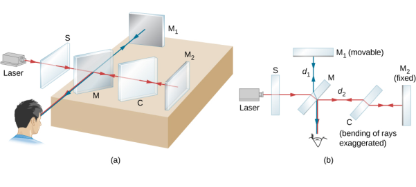
Figure 15: Michelson Interferometer Experiment
Principle
When a beam of light is incident on a beam splitter, it splits up into two beams. One is directed towards a fixed mirror and the other is transmitted towards another movable mirror. The two beams are reflected from the mirrors and are subsequently recombined to produce an interference pattern due to phase or path difference between them.
Construction:
A schematic diagram of the Michelson interferometer is shown in Figure 16. It consists of an extended light source S, a partially coated glass plate G1 called a beam splitter, two highly polished plane mirrors M1and M2, a compensating glass plate G2, and a telescope T. The glass plate G1 is placed at an angle of 45° to the directions of AM1 and AM2 which are perpendicular to each other. The mirror is mounted on a fine pitch screw having a least count of about 10-5 cm. The mirror M1 can be moved parallel to itself by this vernier arrangement. The mirrors M1 and M2 are provided with level fixing screws at their back and with the help of these screws, the mirrors can be made exactly perpendicular to each other or any other desired position.
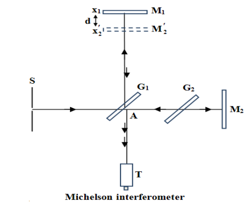
Figure 16: Michelson interferometer
Working
A light beam from the source S falls on the beam splitter G1. It splits into two perpendicular beams AM1 and AM2 of equal intensity. The light beam SA is partially reflected at the back of the glass plate G1 to produce the beam AM1 and it is partially refracted through G1 to produce the beam AM2. The two beams are then reflected along their original path by two separate mirrors M1 and M2 which are located at different distances from the beam splitter. The reflected beam M1 will be transmitted through G1 while the reflected beam M1A suffers reflection at the back of G1 and both reach the telescope T.
Thus, the telescope receives two reflected beams which are originally derived from the same source so that these are mutually coherent. Hence, the two beams M1A T and M2AT will interfere and produces interference fringes in the field of view of the telescope. This process is known as interference by the division of amplitude.
It should be noted that the beam reflected the mirror M1 passes thrice through G1 while the beam AM2 passes only once through G1. Therefore, a compensating plate G2 of the same thickness as G1 is placed exactly parallel to it to equalize the two paths of the light rays when white light is used as a light source.
When one looks into the beam splitter from the telescope, there appears both the mirror M1 and a virtual image M2’ of M2 formed in G1 which are separated by a distance d = x1  x2. Thus, the two interfering beams reflected by the mirrors M1 and M2 appears as reflected from M1 and M2. Hence, the Michelson interferometer is equivalent to a thin air film enclosed between M1 and M2’, see Figure 16.
The path difference between the reflected beams depends on the separation between M1and M2’ and the inclination of M1 and M2’ respectively. Therefore. The interference fringes may be straight, circular, and parabolic is formed.
Circular fringes:
If the two mirrors M1 and M2 are exactly perpendicular, the reflecting surfaces M1 and M2’ are parallel, so that air film between M1 and M2’ is of constant thickness. Hence, it produces circular fringes of equal inclination corresponding to the different values of θ, sees Figure 17. These fringes are called Haidinger's fringes.
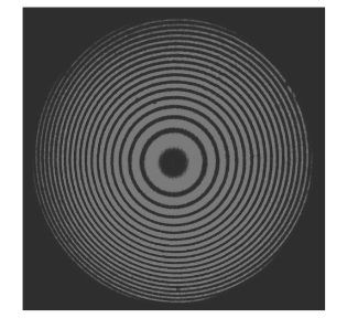
Figure 17: The circular fringe interference pattern produced by a Michelson interferometer
To view these fringes with monochromatic light, the mirrors must be almost perfectly perpendicular to each other. The conditions for constructive and destructive interference pattern can be understood from Figure 18
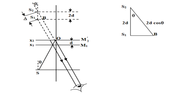
Figure 18: Virtual images from the two mirrors created by the light source and the beam splitter in the Michelson interferometer
Let S1 and S2 be the virtual images of a source S, see Figure 18. If the distance between M1 and M2’ is d, then the distance between the virtual images S1 and S2 will be 2d. The geometrical path difference  between the virtual images S1 and S2 can be obtained from the
  S1S2B (see Figure 18)
 = S2B = 2dcosθ …….... (1)
Where, d = x1  x2 and θ is the angle that the ray from virtual source makes with the normal S2S1. When viewed obliquely into the interferometer, the line OS2 makes an angle θ with the axis. If the light beam reflected from mirror M2 undergoes an abrupt phase change of π or path difference of λ/2, then the optical path deference is:
 = 2dcosθ + λ/2 ……... (2)
The condition for destructive interference (dark fringes) is:
2dcosθ + λ/2= (2m +1) λ/2
Or 2dcosθ = mλ., m = 0, ±1, ±2, ... The order of interference ……... (3)
When viewed along the axis θ = 0,
Then we have:
2d = mλ, m = 0, ±1, ±2,
The condition for constructive interference (bright fringes) is:
2dcosθ + λ/2= mλ m = 1, ±1, +2, ... ……... (4)
2dcosθ = (2m +1) λ/2 m = 0, ±1, ±2, ...
For the given values of m and λ, the above conditions are satisfied by the reflected light from the mirrors M1 and M2’. The reflected light rays form a circular interference pattern.
Expanding the cosine function, it can be shown that the radii of bright fringes are proportional to the square root of integers.
The formation of circular fringes for different conditions is shown in Figure 19.
• When M1 and M2’are separated by a few centimeters, the fringe system has a general appearance as shown in Figure 19(a). If M1is moved towards M2, the distance d decreases, and from Equation (4), as dcosθ is constant, the order of the fringes m decreases, and the fringe radius decreases. Thus, the rings shrink and vanish at the center.
For a ring disappearing each time, 2d decreases by λ or d by λ/2.
2d = m λ since cosθ = 1
• When M1 approaches M2’ r, the rings are more widely spaced as shown in Figure 19 (b).
• When M1 coincides with M2, the distance d = 0, so that path difference becomes zero and the field of view becomes dark or the central fringe spreads out to give a dark field of view as shown in Figure 19 (c).
• If the mirror M1 is moved further, the distance between M1 and M2 again increases to give widely spaced rings (Figure 19 (d)), and finally when the distance is large in centimeters, we get rings with smaller radius (Figure 19 (e)).

Figure 19: Shape of circular fringes by varying the movable mirror M1
Localized fringes: If the two mirrors M1 and M2 are not perfectly perpendicular, i.e M1 and M2 are not exactly parallel, but they are inclined with a considerable distance d as shown in Figure 20(a), the fringes are not exactly straight but it appears as shown in Figure 20(a), This is due to the variation of the path difference with the angle between M1 and M2’. The fringes are curved and are always convex towards the thin edge of the wedge-shaped film. These fringes are called localized fringes.
When the separation between M1 and M2’ decreases, the fringes will move to the left across the field of the telescope, and new fringes crossing the centre of the telescope if d changes by λ/2. If M1 and M2’ are exactly cross with each other, fringes become straight as shown in Figure 20(b), where a wedge-shaped air film is formed. Further movement of M1, as shown in Figure 20(c), the fringes are again curved but in opposite direction. When the distance between M1 and M2’; is too large, the fringes cannot be observed. We conclude that due to the variation of path difference between the reflected light from the mirrors M1 and M2 by changing the distance, the fringe pattern observed contains fringes of equal thickness.
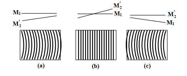
Figure 20: The localized fringe interference pattern–(a) and (c) are depictions of curved fringes, and (b) shows straight, parallel fringes due to wedge-shaped air thin film
White light source
Presently, in most interferometers, sodium vapour lamps, lasers, etc. are used as a light source. The reason for using the monochromatic light beam from these sources is that it has a long coherence length and one can obtain easy interference fringes regardless of the path difference between the two interfering light beams. But at the same time, some stray reflections will give spurious interference fringes, and hence it leads to incorrect results.
To avoid spurious interference fringes, filters can be used. In the case of monochromatic light, maximum contrast fringes can be obtained with precisely defined focus. Therefore, the white light source will be required in the interferometers. Normally, if white light is used as a source. No fringes will be observed for large path difference. However, for small path differences of the order of few wavelengths, coloured fringes are observed.
For observing white light interference, the mirrors are tilted slightly as for localized fringes discussed above and the position of M1 is such that it intersects M2’. At the same time, two important conditions need to be satisfied.
• The position of the zero-order interference fringe must be independent of wavelength, i.e., a dark fringe at the centre of the interference pattern.
• The spacing of the interference fringes must be independent of wavelength.
Overall, the position of interference fringes is independent of order number and wavelength. Generally, in a white light interferometer, only the first condition is satisfied. The white light interference pattern contains a central dark fringe and coloured fringes on either side of the dark fringe. When M1 and M2’coincide, the path difference between the light beams are zero and hence the central fringe is dark in white light fringes. After 8 to 10 fringes from the central dark fringe, so many colours are present at a given point so that it appears white. The white light fringe pattern is shown in Figure 21.
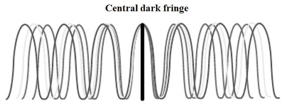
Figure 21: The formation of white light fringes with a dark fringe at the center
Applications
(i) Determination of wavelength of light:
For the determination of the wavelength of light, first, the Michelson interferometer is set for circular fringes with a central bright spot. The mirror M2 is kept fixed and when the mirror M1 is moved, each fringe gets displaced to itself in the field of view of the telescope. If the mirror is moved over a distance d, let m fringes cross the field of view of the telescope, then we have,
2d = mλ ……...... (5)
The wavelength of the light source
λ =2d/m ……...... (6)
By measuring the values of d and m, the wavelength λ can be determined.
(ii) Determination of refractive index of the thin film:
Consider a thin film of thickness t whose refractive index μm is to be measured will be introduced in one of the paths of interferometer beams, say in the path of beam going towards mirror M2. The thin film causes an additional path difference between the two interfering beams. If m be the number of fringes cross the centre of the field of view, then we have,
2(μm— 1)t = mλ
If the reflective index μm and the wavelength λ are known, we can determine the thickness of the thin film
t =
Or
If the thickness of the thin film t and the wavelength λ are known, then the refractive index μm of the thin film can be determined.
μm =  +1 ……...... (7)
(iii) Resolution of spectral lines:
When a source produces two nearby wavelengths, say λ1 and λ2, then it gives two sets of the interference pattern. When the mirror is advanced, the two sets get in step or out of step alternatively. When a bright fringe of λ1 falls on a bright fringe of λ2, there will be a maximum intensity in the field of view of the telescope. On the other hand, when the bright fringe of λ1 falls on the dark fringe of λ2, there will be a. Minimum intensity in the field of view of the telescope. If the distance corresponding to the change from maximum intensity to the minimum intensity is measured as d, then
 = λ2 - λ1 =
  ……...... (8)
If λ= (λ1 + λ2)/2, then the spectral resolution is given by the ratio λ / .
.
Key Takeaways
- Michelson Interferometer Experiment is based on the principle that when a beam of light is incident on a beam splitter, it splits up into two beams. One is directed towards a fixed mirror and the other is transmitted towards another movable mirror.
- The two beams are reflected from the mirrors and are subsequently recombined to produce an interference pattern due to phase or path difference between them.
- The condition for destructive interference (dark fringes) is:
2dcosθ = mλ., m = 0, ±1, ±2, ... The order of interference
- The condition for constructive interference (bright fringes) is:
2dcosθ = (2m +1) λ/2 m = 0, ±1, ±2, ...
- We conclude that due to the variation of path difference between the reflected light from the mirrors M1 and M2 by changing the distance, the fringe pattern observed contains fringes of equal thickness.
- Determination of wavelength of light by using λ =2d/m
- Determination of refractive index of the thin film μm =
 +1
+1 - Resolution of spectral lines is given by the ratio λ /
 . Where
 = λ2 - λ1 =
  and λ= (λ1 + λ2)/2
The Mach–Zehnder interferometer was developed by the physicists Ludwig Mach and Ludwig Zehnder. The Mach–Zehnder interferometer is a particularly simple device for demonstrating interference by division of amplitude.
The Mach–Zehnder interferometer consists of two beam splitters and two totally reflecting mirrors. One beam splitters is for splitting the incident beam and the other for combining the split-beams. Mirrors M1 and M2 direct the beams appropriately. The two waves within the apparatus travel along separate paths. A difference between the optical paths can be introduced by a slight tilt of one of the beam splitters. Since the two paths are separated, the interferometer is relatively difficult to align. These two waves are combined by the second beam splitter.
In Mach–Zehnder interferometer BS1 and BS2 are beam splitters, M1 and M2 are mirrors, TC is test chamber, D is detector. The centers of the beam splitters and mirrors lie on the corners of a parallelogram as shown in figure.
One arm of the interferometer contains the test chamber and compensating elements (not shown in the figure) are kept in the other arm to equalize the optical path lengths.
An object interposed in one beam will alter the optical path length difference, thereby changing the fringe pattern.
One beam passes through the optically flat windows of the test chamber, while the other beam traverses appropriate compensator plates. The beam within the chamber will propagate through regions having a spatially varying index of refraction. The resulting distortions in the wavefront generate the fringe contours
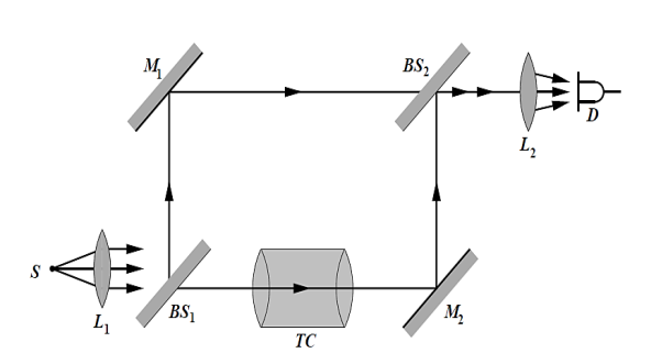
Figure 22: Mach–Zehnder interferometer
The refractive index changes associated with the density changes in the test chamber can be accurately determined in terms of the fringe displacements. The contours of the fringes determine local density changes within the test chamber under different experimental conditions. The fringes can be localized at any convenient region in the test chamber by appropriately tilting one of the mirrors.
The interferometer finds countless applications. It has even been used, in a somewhat altered yet conceptually similar form, to obtain electron interference fringes. A common application of the device is to observe the density variations in gas-flow patterns within research chambers (wind tunnels, shock tubes, etc.). This interferometer is particularly useful for plasma diagnostics and gas flow studies (in a wind tunnel, for example).
Key Takeaways
- The Mach–Zehnder interferometer is a particularly simple device for demonstrating interference by division of amplitude.
- The Mach–Zehnder interferometer consists of two beam splitters and two totally reflecting mirrors.
- An object interposed in one beam will alter the optical path length difference, thereby changing the fringe pattern.
- The refractive index changes associated with the density changes in the test chamber can be accurately determined in terms of the fringe displacements.
- The contours of the fringes determine local density changes within the test chamber.
DIFFRACTION: FRAUNHOFFER DIFFRACTION DUE SINGLE SLIT
Diffraction
When the light falls on the obstacle whose size is comparable with the wavelength of light then the light bends around the obstacle and enters in the geometrical shadow. This bending of light is called diffraction.
FRAUNHOFFER DIFFRACTION AT SINGLE SLIT
The adjacent figure represents a narrow slit AB of width ‘e’. Let a plane wavefront of monochromatic light of wavelength ' ' is incident on the slit. Let the diffracted light be focused by means of a convex lens on a screen. According to Huygen Fresnel, every point of the wavefront in the plane of the slit is a source of secondary wavelets. The secondary wavelets traveling normally to the slit i.e., along OP0 are brought to focus at -+
AzP0 by the lens. Thus P0 is a bright central image. The secondary wavelets traveling at an angle ' ' are focused at a point P1 on the screen.
The intensity at the point P1 is either minimum or maximum and depends upon the path difference between the secondary waves originating from the corresponding points of the wavefront.
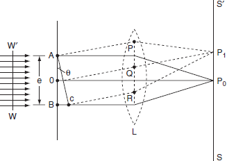
Figure 23: Fraunhoffer diffraction at single slit
Theory:
In order to find out the intensity at P1, draw a perpendicular AC on BR.
The path difference between secondary wavelets from A and B in direction θ is BC i.e,

So, the phase difference,


Let us consider that the width of the slit is divided into ‘n’ equal parts and the amplitude of the wave from each part is ‘a’.
So, the phase difference between two consecutive points
 ........... (1)
Then the resultant amplitude R is calculated by using the method of vector addition of amplitudes
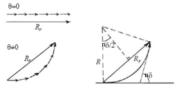
Figure 24: Mathematical analysis of Fraunhoffer diffraction at single slit
The resultant amplitude of n number of waves having same amplitude 'a' and having common phase difference of ' ' is
' is
 ................... (2)
Substituting the value of  in equation (2)
R = a  ................... (3)
Substituting =
=  .esinθ in equation (3)


As  is small value; sin
R = n
And na = A
Therefore
R =A ................... (4)
Therefore, the Intensity is given by
I =R2 = A2  ................... (5)
Case (i): Principal Maximum:
Eqn (4) takes maximum value for
 = 0
= 0
 =
=  .esinθ = 0
Sinθ = 0 or θ=0
The condition
The condition θ=0 means that this maximum is formed by the secondary wavelets which travel normally to the slit along OP0 and focus at P0. This maximum is known as “Principal maximum”.
Intensity of Principal maxima


Therefore
Imax = R2max = A2
Case (ii): Minimum Intensity positions:
Equation (3) takes minimum values for sin The values of '
 ' which satisfy sin
 are
are


 where
where  ………...(6)
In the above equation (6) n = 0 is not applicable because corresponds to principal maximum. Therefore, the positions according to equation (6) are on either side of the principal maximum.
Case (iii): Secondary maximum:
In addition to principal maximum at  = 0, there are weak secondary maxima between minima positions. The positions of these weak secondary maxima can be obtained with the rule of finding maxima and minima of a given function in calculus. So, differentiating equation (5) and equating to zero, we have
 =
=  (A2
(A2  ) =0
) =0
 = 2A2
= 2A2  (
(  )(
)( =0
=0
A2  0;
0;  =0
=0
Because  =0 correspond to minima positions
 =0
=0
 ………... (7)
The values of ' ' satisfying the equation (7) are obtained graphically by plotting the curves
  and
and  on the same graph.
The points of intersection of the two curves gives the values of  which satisfy equation (7).
The points of intersections are

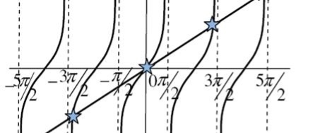
Figure 25: Variation of intensity
But  , gives principal maximum, substituting the values of
  in equation (5), we get


And so on.
From the above expressions, Imax, I1, I2,I3… it is evident that most of the incident light is concentrated at the principal maximum.
INTENSITY DISTRIBUTION GRAPH
A graph showing the variation of intensity with ' ' is as shown in the adjacent figure
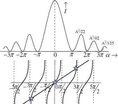
Figure 26: Intensity Distribution Graph
FRAUNHOFER DIFFRACTION AT CIRCULAR APERTURE
Airy in 1835 solved the problem of diffraction at a circular aperture.
When diffraction due to a circular aperture takes place, it forms an intensity pattern. An intensity pattern is formed because of the distribution of amplitude of waves.
An intensity pattern consists of a bright central band surrounded by concentric circular bands of rapidly decreasing intensity. This pattern is known as Airy pattern. The 1st maximum is roughly 1.75% of the central intensity. 84% of the light arrives within the central peak called the airy disc.
Let us consider a circular aperture of diameter AB= d is shown in in figure below. A plane wave front WW' is incident normally on this aperture. Every point on the plane wave front in the aperture acts as a source of secondary wavelets. The secondary wavelets spread out in all directions as diffracted rays in the aperture.
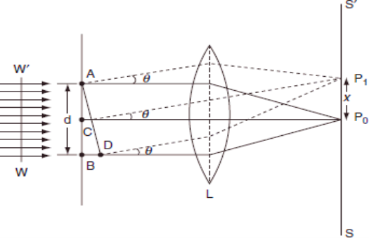
Figure 27: Fraunhofer diffraction at circular aperture
Place a convex lens (L) between the aperture and the screen. The screen is at the focal plane of the convex lens. The diffracted secondary wavelets are converged on the screen SS' through a convex lens L. These diffracted rays traveling normal to the plane of aperture [i.e., along CP0] are get converged at P0.
All these waves coming from circular aperture travel same distance to reach P0 and there is no path difference between these rays. Hence a bright spot is formed at P0 known as Airy's disc. P0 corresponds to the central maximum.
Now consider the secondary waves traveling at an angle  with respect to the direction of CP0. All these secondary waves travel in the form of a cone and hence, they form a diffracted ring on the screen. The radius of that ring is x and its center is at P0.
Now consider a point P1 on the ring, the intensity of light at P1 depends on the path difference between the waves at A and B to reach P1.
The path difference is given by
BD = ABsin = dsin
The diffraction due to a circular aperture is similar to the diffraction due to a single slit.
Hence, the intensity at P1 depends on the path difference dsin .
.
If the path difference is an integral multiple of  . Then intensity at P1 is minimum. On the other hand, if the path difference is in odd multiples of images, then the intensity is maximum. i.e.,
For minima
Dsin = n
= n ………….(1)
For maxima
Dsin = (2n-1)
 ………….(2)
Where n = 1, 2, 3... Etc. n = 0 corresponds to central maximum.
The Airy disc is surrounded by alternate bright and dark concentric rings, called the Airy's rings. The intensity of the dark ring is zero and the intensity of the bright ring decreases as we go radially from P0 on the screen. If the collecting lens (L) is very near to the circular aperture or the screen is at a large distance from the lens, then
Sin
 ………….(3)
Where, f is the focal length of the lens.
Also from the condition for first secondary minimum [using equation (1)]
Sin
 ………….(4)
Equations (3) and (4) are equal


So x =  ………….(5)
But according to Airy, the exact value of x is
x =  ………….(6)
Using equation (6) the radius of Airy's disc can be obtained. Also from this equation we know that the radius of Airy's disc is inversely proportional to the diameter of the aperture. Hence by decreasing the diameter of aperture, the size of Airy's disc increases.
Key Takeaways
- The intensity in case of Fraunhoffer diffraction at single slit at the point P1 is either minimum or maximum and depends upon the path difference between the secondary waves originating from the corresponding points of the wavefront.
- Intensity is given by I =R2 = A2

A set of large number of parallel slits of same width and separated by opaque spaces is known as diffraction grating.
Diffraction gratings are much more effective than prisms for dispersing light of different wavelengths so they are used almost exclusively in instruments designed to detect and identify characteristic spectral lines. There is nothing mysterious about these devices.
Fraunhofer used the first grating consisting of a large number of parallel wires placed side by side very closely at regular separation. Now the gratings are constructed by ruling the equidistance parallel lines on a transparent material such as glass with fine diamond point. The ruled lines are opaque to light while the space between the two lines is transparent to light and act as a slit.
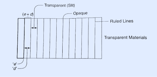
Figure 28: Plane Transmission Grating
Let ‘e’ be the width of line and ‘d’ be the width of the slit.
Then (e + d) is known as grating element.
If N is the number of lines per inch on the grating then
(𝑒+𝑑)=1𝑖𝑐ℎ=2.54𝑐𝑚
(𝑒+𝑑)=2.54𝑐𝑚/𝑁
Commercial gratings are produced by taking the cost of actual grating on a transparent film like that of cellulose acetate. Solution of cellulose acetate is poured on a ruled surface and allowed to dry to form a thin film, detachable from the surface. This film of grating is kept between the two glass plates.
Example: A parallel beam of monochromatic light of wavelength 500nm is inclined normally on a plane diffraction grating 4000 per centimetre. Calculate the angle of diffraction for first order principal maximum.
Solution:
Given: number of lines per cm =4000
Grating element e+b = 1/4000 cm = 2.5 x 10⁻⁶m
λ=500 nm
Order n =1
(e+b) sinθ =nλ
Sinθ = nλ / (e+b)
Sinθ = 1 x 500 x 10-9 / 2.5 x 10⁻⁶
Sinθ =0.2
θ =sin-1 0.2
θ = 11.5o
RESOLVING POWER OF DIFFRACTION GRATING
It is defined as the capacity of a grating to form separate diffraction maxima of two wavelengths which are very close to each other
It is measured by λ/dλ where dλ is the smallest difference in two wavelengths which are just resolvable by grating and λ is the wavelength of either of them or mean wavelength.
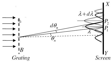
Figure 29: Resolving Power of Diffraction Grating
Let AB represent the surface of a plane transmission grating having grating element (e+d) and N total number of slits.
Let a beam of light having two wavelengths by λ and dλ is normally incident on the grating. Let P1 is nth primary maximum of a spectral line of wavelength λ at an angle of diffraction  and P2 is the nth primary maximum of wavelength λ+dλ at diffracting angle θ+dθ.
According to Rayleigh criterion, the two wavelengths will be resolved if the principal maximum λ+dλ of nth order in a direction θ+dθ falls over the first minimum of nth order in the same direction θ+dθ.
Let us consider the first minimum of l of nth order in the direction θ+dθ as below.
The principal maximum of  in the θ direction is given by
(e+d)sinθ =nλ ………………(1)
The equation of minima is
N(e+d)sinθ = mλ ………………(2)
Where m takes all integers except 0, N, 2N, …, nN, because for these values of m, the condition for maxima is satisfied.
Thus first minimum adjacent to nth principal maximum in the direction θ+dθ can be obtained by substituting the value of ‘m’ as (nN+1).
Therefore, the first minimum in the direction of θ+dθ is given by
N(e+d)sin(θ+dθ) = (nN+1)λ
(e+d)sin(θ+dθ) = (n+ )λ ………………(3)
The principal maximum of λ+dλ in direction θ+dθ is given by
(e+d)sin(θ+dθ) = n(λ+dλ) ………………(4)
Dividing eqn(3) by equation (4), we get
(n+ )λ = n(λ+dλ)
nλ + = nλ + ndλ
 = ndλ
= ndλ
 = nN
= nN
Resolving Power =  = nN ………………(5)
Thus the resolving power is directly proportional to
(i) The order of the spectrum ‘n’
(ii) The total number of lines on the grating ‘N
Example: A grating has 1100 lines ruled on it. What is difference between the two wavelengths that just appear resolved in the first order spectrum in the region of wavelength λ = 660 nm?
Solution:
N = 1100 nm
λ = 660 x 10-9 m
n = 1
R = λ /dλ =Nn
dλ = λ /Nn
dλ = 660 x 10-9 / 1100 x 10-9 x 1
dλ = 0.6 x 10⁻⁹ m
Key Takeaways
- A set of a large number of parallel slits of the same width and separated by opaque spaces is known as a diffraction grating.
- Resolving power of diffraction is defined as the capacity of a grating to form separate diffraction maxima of two wavelengths that are very close to each other
- Resolving Power =
 = nN
= nN
NUMERICAL PROBLEM
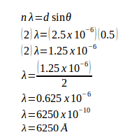
Example: A grating containing 4000 slits per centimetre is illuminated with a monochromatic light and produces the second-order bright line at a 30° angle. What is the wavelength of the light used? (1 Å = 10-10 m)
Solution:
The distance between slits (d) = 1 / (4000 slits / cm) = 0.00025 cm = 2.5 x 10⁻⁴ cm = 2.5 x 10⁻⁶ meters
Order (n) = 2
Sin 30o = 0.5
1 Å = 10-10 m
Wavelength of the light (λ) =?
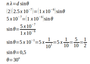
Example: A monochromatic light with a wavelength of 2.5x10⁻⁷ m strikes a grating containing 10,000 slits/cm. Determine the angular positions of the second-order bright line.
Solution:
Given
The distance between slits (d) = 1 / (10,000 slits / cm) = 0.0001 cm = 1 x 10⁻⁴ cm = 1 x 10⁻⁶ m
Order (n) = 2
Wavelength (λ) = 2.5 x 10⁻⁷ m
Angle (θ)
Example: A monochromatic light with wavelength of 500 nm (1 nm = 10-9 m) strikes a grating and produces the second-order bright line at an 30° angle. Determine the number of slits per centimetre.
Solution:
Wavelength (λ) = 500.10-9 m = 5.10-7 m
θ = 30o
n = 2
Distance between slits:
d sin θ = n λ
d (sin 30o) = (2)(5.10-7)
d (0.5) = 10.10-7
d = (10.10-7) / 0.5
d = 20.10-7
d = 2.10-6 m
Number of slits per centimetre:
x = 1 / d
x = 1 / 2.10-6 m
x = 0.5.106 / 1 m
x = 0.5.106 / 102 cm
x = 0.5.104 cm
x = 5.103 /cm
x = 5000 /cm
Example: A monochromatic light with wavelength of 500 nm (1 nano = 10-9) strikes a grating and produces the fourth-order bright line at an 30° angle. Determine the number of slits per centimetre.
Solution:
Wavelength (λ) = 500.10-9 m = 5.10-7 m
θ = 30o
n = 4
Distance between slits:
d sin θ = n λ
d (sin 30o) = (4)(5.10-7)
d (0.5) = 20.10-7
d = (20.10-7) / 0.5
d = 40.10-7
d = 4.10-6 m
Number of slits per centimetre:
x = 1 / 4.10-6 m
x = 0.25.106 / m
x = 0.25.106 / 102 cm
x = 0.25.104 / cm
x = 25.102 per cm
x = 2500 per cm
Reference Books
- Fundamentals of optics-Jenkins and White. McGraw Hill Publication
- A Text Book of Optics Subrahmanyam, BrijIal, S. Chand Publication
- Optics by Ajay Ghatak
- Engineering physics - Avadhanalu and Kshirsagar, S.Chand Publication