Unit - 6
Spillway and Energy Dissipation Devices
- It is an arrangement provided at the crest of dam to expel the excess water rises above the full reservoir level.
- This is necessary otherwise water will go on rising even above HFL and will start flowing from top of dam which may affect stability of dam.
- Therefore it is very essential to provides spillway to dispose surplus water on downstream side.
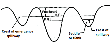
Fig 1: Location of spillway
Definition: The passage provided for disposal of surplus flood water on the downstream side without affecting stability of dam are called as spillways.
Location of Spillway
Spillway are located at
1. In the body of damn.
2. At one end of the dam.
3. Away from the body of dam independently.
Generally in gravity dam spillways are provided in the body of dam.
Separate spillway is provided in case of earthen dam.
Factors Affecting Spillway Capacity
The various factors which affect spillway capacity are as follows:
1. Inflow.
2. Capacity of outlet.
3. Possible damage.
4.Available storage capacity.
5. Gates of spillway.
6. Site condition.
7. Type of dam and its purpose.
8. Height of the crest of spillway.
9. Solid material brought by river its nature and amount.
10. Geological condition.
Types of Spillways based on operation
1. Emergency spillway
2. Service spillway
3. Axillary spillway
1. Emergency Spillway:
- It is provided with an earthen dam. In such spillway part of the length of earthen dam is kept weak above FTL/FRL (Full tank/Reservoir level).
- When abnormal high intensity flood occurs the weaker portion gets washed and flood water flows through that portion which acts as additional spillway and thus avoids possibility of failure of the dam.
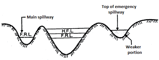
Fig 2: Emergency spillway
The various conditions which may lead to emergency are:
a) When there is mal functioning of spillway gate.
b) When actual flood exceeds the design flood etc.
2. Service Spillways or main spillway
The service spillways are masonry or concrete structure provided with necessary component. It is necessary for all dams and in most dam it is the only spillway designed to pass design flood.
3. Auxiliary spillway
This type of spillway is provided so as to supplement the main spillway. It operates only when the design floods in the main spillway is more or exceed.
Key Takeaways:
The passage provided for disposal of surplus flood water on the downstream side without affecting stability of dam are called as spillways.
Types of Spillways based on gates
1. Gated spillway
2. Un-gated spillway or uncontrolled spillway
1. Gated spillway
Gate are provided over the crest of spillway. It store more water and efficiently and effectively control the outflow from upstream and downstream side.
2. Un-gated spillway or uncontrolled spillway
In such type, no gates are provided over the crest to control the flow and hence it does not need any operation of gate. Surplus flow of water cannot be controlled by un-gated spillway.
Classification of Spillway Based on Features
1. Ogee Spillway
2. Bar Spillway
3. Straight drop spillway or free overfall spillway
4. Side channel spillway.
5. Chute or open channel or trough spillway
6. Shaft spillway or moving glory spillway
7. Siphon spillway
(i) Saddle siphon spillway
(ii) Volute siphon spillway
8. Tunnel spillway
9. Stepped spillway
10. Saddle spillway
- Ogee Spillway
The shape of spillway is ogee or S shaped. The main difference between free overfall spillway and ogee spillway is that case of free overfall spillway water flowing over the crest of spillway drops vertically as freeset where in ogee shaped spillway water is guided smoothly over the crest and is made to guide over the downstream face of the spillway.
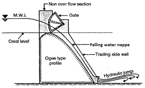
Fig 3: Ogee-spillway
2. Bar Spillway
- It consists of rectangular masonry concrete bar with crest width1 to 1.5 m. It is low height spillway, founded on concrete block, rest on hard rock foundation sometime precast concrete blocks are used for coping of the crest.
- The top of crest is at FRL.
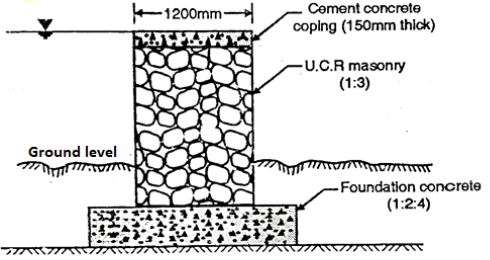
Fig 4: Bar channel Spillway
3. Straight drop spillway or free overfall spillway or Vertical drop Spillway
Definition: The spillway in which the flow drops freely from the crest is called as straight drop spillway or free overfall spillway. Such type of spillway is not suitable for high drops.
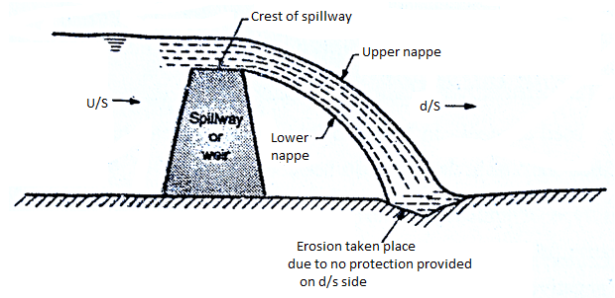
Fig 5: Straight drop spillway without protection on downstream side
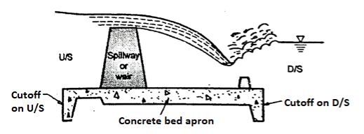
Fig 6: Straight drop spillway provided protection on downstream side
Three provisions or Methods to avoid erosion on the d/s side
1. An artificial pool can be created by constructing a low auxiliary dam downstream of the main structure.
2. By excavating a basin which is then provided with a concrete apron.
3. Floor blocks and an end sill can be provided as shown in Fig., to help in the establishment of the jump and thus reduces the d/s scour.
If tailwater depths are sufficient, then a hydraulic jump forms when jet falls freely from the crest, in such case, a long flat concrete apron may be provided.
4. Side channel spillway
When it is not possible to use overfall spillway especially in embankment dams, then side channel spillway is more suitable. In such type of spillway, water flow after passing over the crest is further conveyed in the side channel which running parallel to the crest as shown in Fig.
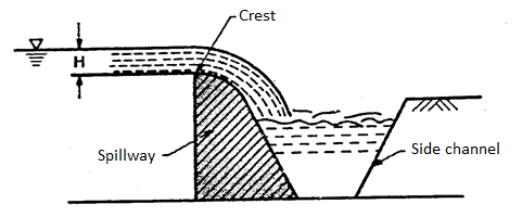
Fig 7: Side channel spillway
This type of channel is preferred under following situations:
(i) It is adopted in case of a long overflow crest provided to limit the surcharge head.
(ii) It is adopted or preferred when the control structure is to be joined to a narrow discharge channel.
(iii) It is preferred when the abutments are very steep.
5. Chute Spillway or Trough Spillway
- In case of concrete gravity dams, when the spillway is located within the dam body in the same valley, then an ogee spillway is more suitable.
- However in case of earthen dam or rock fill dams, a separate spillway and but away from main valley is generally constructed in a saddle or in a flank.
- Even in case of gravity dam, if the main valley is narrow, then a separate spillway is required to be provided.
- In such situation, a separate spillway like chute spillway or trough spillway is the best option because this type of spillway is a simplest type, lighter and suitable for any type of foundation. In addition to this, it can be easily constructed and provided independently with low cost. Chute spillway or trough spillway can easily be provided on earth fill dam and rock fill dam. Chute spillway is sometimes termed as a waste weir.
6. Shaft spillway or morning glory spillway
This type of spillway consists of a vertical flaring funnel act as the crest of the spillway and its bottom end connected to the shaft either vertical or inclined which is further connected at its lower and to the a horizontal tunnel extending through or around the dam as shown in Fig. The water flow passes though tunnel is taken to the downstream river channel.
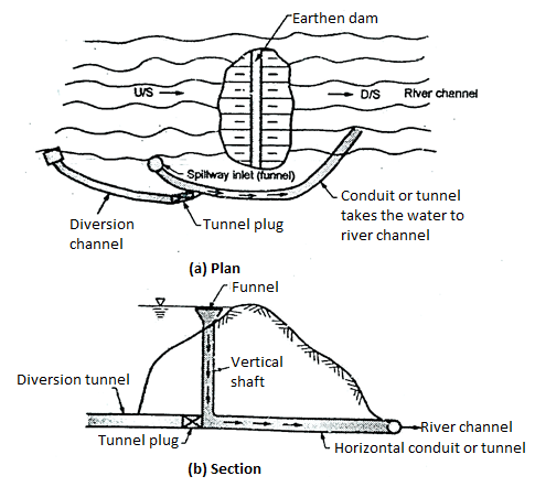
Fig 8: Shaft spillway
7. Siphon spillway
- This type of a spillway is more suitable when the discharge to be carried is not large and available space is small or limited.
- The siphon spillway automatically maintain the water surface elevation in the dam within the limited range by siphonic action.
- It consist of a closed U-shaped inverted conduit provided with the inlet, short upper leg and throat portion. Siphon spillway taken the water from upstream side of dam to the downstream side of the dam by the principle of siphonic action. Fig. Shows siphon discharging freely.
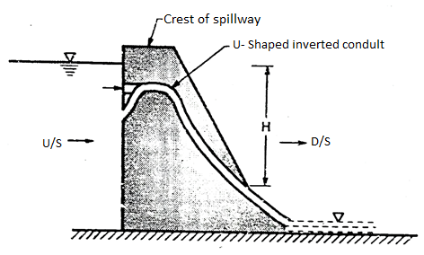
Fig 9: Siphon spillway
8. Tunnel spillway
- Definition: The tunnel spillway in which discharge of water can be conveyed by a closed channel around or under the dam. It is also called as conduit spillway.
- The closed channel can be in the form of the vertical shaft or inclined shaft or in the form of a horizontal tunnel.
- This type of spillway is designed so as to flow partly full because full flow due to siphonic action which may develop the negative pressure. In order to maintain free flow, the ratio of area of flow to the total conduit area is often limited to about 75 %. So as to avoid also unsteady flow through spillway, air vents are also provided at various critical points and junction.
9. Stepped spillway
- This type of spillway has been used for over 3000 years. Now a days new construction material like RCC gabions and design technique have increased the interest of stepped spillways and chutes. The steps in spillway produce considerable energy dissipation along chute.
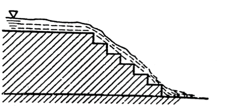
Fig 10: Stepped Spillway
10. Saddle spillway
- There may be one or more natural depressions or saddles providing spillway in some basins formed by a dam.
- A site which has a saddle is very desirable and economical, if the saddle is suitable for locating the spillway.
- Fig. shows saddle spillway. This type of spillway are constructed when any of the above type of spillway is not possible. It is usually necessary for the saddle to be on firm rock.
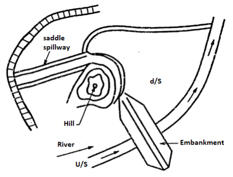
Fig 11: Saddle spillway
Key Takeaways:
- Even in case of gravity dam, if the main valley is narrow, then a separate spillway is required to be provided.
The various essential requirement of spillways are:
1. It must have adequate discharge capacity.
2. It should be provided with some device for energy dissipation.
3. Its discharge should be such that it should not cause flooding on downstream side.
4. It must be safe.
5. It's surface must be erosion resistant.
6. It should be so located that it should not erode downstream toe of dam.
- Spillways are structural elements construct to provide safe release of floodwater from the dam towards a downstream region.
- Throughout regards to provide adequate power, the spillway should be pneumatically s well as structurally stable as well as positioned in a quiet manner that perhaps the discharge does not trigger unacceptable flooding downstream at just the toe of the dam resulting in the collapse of the dam as well as other appurtenant structures.
- Uncontrolled degradation of beds as well as deposit materials caused by poor construction of spillways and energy dissipation system has triggered not just to significant safety issues but also high maintenance expenses are associated yearly during the monsoon while the spillway has been in service.
- The bonding layer of spillways shall be resistant to erosion in order to endure the high speed flow produce by the decrease in the surface of the water from its reservoir stage upstream to that same drain water downstream of the dam.
Ogee spillway or overflow spillway is the most common type of spillway provided on gravity dam profile of ogee spillway is S shaped or ogee overflow or ogee spillway are classified high and low spillway depends upon of the height of the spillway (P) crest measured from the river bed to the design head (H).
Technical terms
(i) Head (H)
(ii) Design head (Hd)
(iii) Head due to velocity of approach (Ha)
(iv) Total energy head (He)
(i) Head (H)
Definition: The distance measured vertically from the water surface in upstream to the crest axis is called as head (H).
(ii) Design head (Hd)
Definition: The value of head for which the ogee profile is designed, is called as design head (Hd).
(iii) Head due to velocity of approach (Ha)
Head due to velocity of approach is the velocity head given by following expression
 where Va = Velocity of approach
(iv) Total energy head (He)
When the actual head is added in the head due to velocity approach, then it gives total energy head (He).
He = H + Ha
If H = H₂
Then He = Hd + Ha, design head and Ha = head due to velocity where H₂ approach.
- When water flows from crest and if the difference in upstream and downstream water level is more. This causes very high velocity.
- This high velocity has a very high kinetic energy which can cause dangerous course of the channel bed causing failure of spillway.
- Therefore it is essential to reduce this kinetic energy of flow and this is done by energy dissipaters.
- Thus energy dissipaters is a structure constructed near toe of spillway to reduce the high energy of flow.
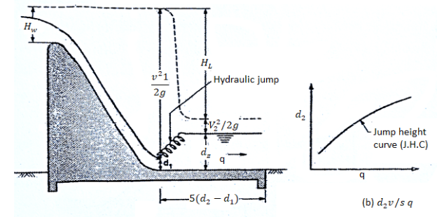
Fig 12: Hydraulic jump type energy dissipater
The different types of energy dissipaters are:
1. Hydraulic jump type.
2. Bucket type.
- 'Hydraulic jump is the jump of water take place when flow changes from super critical to sub critical.'
- Definition: When super critical flow strikes against sub critical a sudden rise in surface of the former takes place which is called as hydraulic jump, which is accompanied by large scale turbulence and thus destroys most of energy of super critical flow.
- Due to heavy turbulence it is essential to produce hard floor.
- For hydraulic jump sloping glacis are preferred to a horizontal bed and jump is made to occur on the glacis only.
- In bucket type energy dissipaters flow of water is directed into air and thus fall occurred away from toe of dam. These are suitable under any conditions of tail water provided good hard rock is available. These are more economical than hydraulic jump type.
- The energy is destroyed by a creation of jet and impact of water on the bed of river and scouring takes place which is small and away from toe.
Energy Dissipation through buckets:
Types of buckets
Buckets are mainly classified into three types:
Types of buckets
1. Solid roller bucket
2. Slotted roller bucket
3. Ski-jump bucket
- Solid roller bucket
- This type of bucket consist of a concave circular apron of large radius and a deflector lip.
- When water flows over the solid roller bucket, then complete sheet of water leaving the bucket is jumped upward by the bucket lip and two elliptical rollers are developed.
- Two elliptical rollers moves in clockwise direction and anticlockwise direction.
- Definition: The bucket rollers developed on the surface of roller moves in anticlockwise direction known as bucket roller or surface roller.
- Definition: The other bucket rollers developed on the ground surface moves in the clockwise direction called as ground rollers.
2. Slotted roller bucket
- A slotted roller bucket consists of concave circular apron having large radius; like solid circular bucket, only difference is that it has slotted deflector lip.
- In such type of bucket also two rollers are developed as developed in solid roller bucket. But in this type water leaves lip of the bucket at a flatter angle and only a part of it get jumped upwards.
- In this case, less violent ground roller occurs which makes the smoother flow on d/s side.
- The slotted roller buckets are suitable only for a limited range of tail water depth because excessive large jet of water leaving lip get depressed and drive to the river bed which will scour the bed.
3. Ski-jump bucket
- When tail water depth is less, then in such case a ski-jump bucket can be used. In such bucket the lip of the bucket is shaped in such way that the complete sheet of water flowing he bucket is jumped or deflected as a free jet. This free jet further falls back into the river at a safe distance away from the spillway.
- Ski-jump bucket dissipates the energy by air resistance, breaking up of the jet into bubbles and impact of falling jet.
- Various agencies have developed the various types of stilling basin and the designs of stilling basin have been innovated on the basis of long experience in dam construction field and experiment on various model with a basic view of protection and economy.
- Stilling basins are concrete apron provided with auxiliary devices like chute blocks, battle walls sills, dentated sills etc. All these devices can useful in dissipating the energy of water flow by offering resistance to flow and thus stabilize the flow within shorter length of the basin and hence achieve the economy.
Definition of stilling basin
A structure built with the auxiliary devices on the downstream side which dissipates the energy of water flow by offering resistance is called stilling basin.
Types of Stilling Basin:
- Chute blocks
- Chute blocks are the row of small projections look like the teeth of saw. These blocks are provided at the entrance of the stilling basin.
- When the flow over the spillway comes towards the stilling basin then chute blocks lifts some part of flow and hence produces a shorter length of the jump which is not possible without chute blocks. Chute blocks also help in stabilising the flow and finally improve the jump performance.
2. Battle Piers or friction blocks
- Battle piers are the blocks which are located within the basin across the basin floor.
- Theses piers break the flow of water and dissipate energy developed by impact. These piers are suitable for low spillway or weirs and unsuitable for large spillway due to cavitations.
3. End sills and dentated sills
- Various Agencies has standardised stilling basin for different ranges of Froude numbers.
- At the end of the stilling basin, sill or sometimes dentated sills is generally provided, which diffuses the residual portion of high velocity jet flowing at the end of basin.
4. Stilling basin Type I, II and IV(IS:4997-1968)
- I.S.I. Standardised the basin in four types. Type I and II are used for Froude number less than 4.5 with horizontal apron and type II and IV are used for Froude number more than 4.5 with sloping apron.
5. Hydraulic jump type stilling basin with horizontal apron
- Hydraulic jump type stilling basin with horizontal apron is more suitable and provides best solution for energy dissipation, when the tail water rating curve nearly follows the hydraulic jump curves.
- Hydraulic jump type stilling basins are recommended for spillway having weak bed conditions, end weirs and barrages on sand and gravel.
Design of stilling basin:
- Stilling basin type I
F < 4.5 and this type of basin is generally encountered on weirs and barrages. The various factors involved in the design of stilling base type I are as follows:
The various factors involved in the design of stilling base type I
(i) Elevation of basin floor
(ii) Basin length and depth
(iii) Basin appurtenances for basin type
(a) Chute blocks
(b) Basin blocks
(c) End sill or Dentated sill
i) Elevation of basin floor
 = Head loss in hydraulic jump


S = spacing
By knowing the value, we can determine the following formula
 =
= 
Ii) Basin length and depth
Let,  = Length of the basin can be obtained from the curve as shown in fig
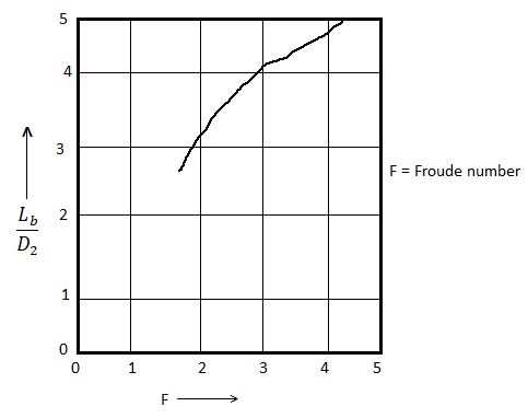
Fig 13: Recommended length of stilling basin
- End sill is provided to the basin. Note that the basin floor level should be taken raised above the level required from the consideration of sequent depth.
- Because of site condition, the rise of the floor becomes critical, then in such cases, chute blocks and basin blocks are provided.
- If the velocity of flow at the location of basin blocks is more than 15 m/s, basin blocks should not be used and floor or basin should be kept at a depth equal to D₂ below the tail water level. The tail water depth should not be more than 10% of D₂.
Iii) Basin appurtenances for basin type I
a) Chute blocks
Height of chute block should be equal to 2 on the glacis slope and its top length should also equal to 2
 width of the chute block should be equal to
  and its spacing equal to 2.5
b) Basin blocks
The height of basin block in the form of  can be determined from the curve obtained by the graph of Froude number. The width and spacing of the basin block should be equal to its height.
c) End sill or Dentated sill
Recommended height of end sill will be 0.2 
2. Stilling basin type II
(i) Elevation of basin floor
(ii) Basin length and depth
(iii) Basin appurtenances for basin type
(a) Chute blocks
(b) Basin blocks
(c) End sill or Dentated sill
i) Elevation of basin floor
Same procedure of stilling basin type I used to determine elevation of basin floor.
Ii) Basin length and depth
The length of the basin determined from curve of graph of Froude number.
The basin should be provided with end sill and chute blocks. If the velocity of the flow at the location of the basic block is more than 15m/sec, basin block are not recommended to provide and in such situation the floor of the basin should be at a depth equal to D2 below tail water level.
Iii) Basin Appurtenances
a) Chute block
The height, spacing and width of chute blocks should be equal to D1.
Not that width and spacing can be changed so as to eliminate the frictional block.
b) Basin block
The height of basin block in terms of D1 can be obtained from the curve of graph of Froude number.
c) End sill
Recommendation of end sill is as same as type I.
3. U.S.B.R. Stilling Basin II
- U.S.B.R. Recommended for basin II for large structure like dam spillway, large canal structure etc. When Froude number is more than 4.5 then U.S.B.R. Stilling basin II are provided.
4. U.S.B.R. Stilling Basin IV
- Note that only rectangular cross section of a basin is applicable in such type II.
- IF there is formation of oscillating within range of Froude number i.e. 2.5 to 4.5, then they can be controlled by providing large chute blocks.
Key Takeaways:
- Spillways are structural elements construct to provide safe release of floodwater from the dam towards a downstream region.
References:
- Tech-max publication
- Techno max publication
- Foundation engineering by Dr. B.C. Punmia, Laxmi Publication.
- Geotechnical engineering by p. Purushottam Raj, Tata MC Grawhill