Unit - 6
Soil hydraulic and seepage analysis
- In 1856 Darcy studied and demonstrated experimentally, the velocity of laminar flow through homogeneous soil mass, which states that, "The rate of flow or the discharge per unit time is proportional to the hydraulic gradient."
q= K.i.A
V=q/A
V i, V=Ki
Where,
q= discharge per unit time
A= total c/s area of soil mass, perpendicular to the direction of flow
i =hydraulic gradient K Darcy's coefficient of permeability
v =velocity of flow, or average discharge velocity
- If a soil sample of length 1 and cross-sectional area A, is subjected differential head of water hA-hB, the hydraulic gradient i will be equal to (hA-hB)/L and
We have,
q=KA (hA-hB)/L
When hydraulic gradient i = 1, then k=v
Key Takeaways:
Darcy’s law states that, "The rate of flow or the discharge per unit time is proportional to the hydraulic gradient."
Constant head method as per IS2720:
- It is based on measuring the volume of water flowing through a soil sample of known cross sectional area A and length L in time t under a constant head h of water.
- The arrangement is shown in Fig.
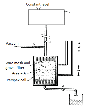
Fig: Constant head permeability test
- The soil sample is enclosed in a perspex cylindrical tube. A number of manometer points are provided of the side of the cylinder. These can be used in pairs.
- One such pair is shown in the figure.
- Water is allowed to flow through the soil at a constant head 'h' as indicated by the level difference in manometer tubes.
- The quantity of water or volume of water V collected in time t is measured, from which discharge q is calculated. The coefficient of permeability is then calculated as,
K= =
=
Where q=v/t=discharge in m3/s
V=volume of water collected in m3 in time t sec
A=cross sectional area of specimen in m
h =level difference between the manometer tubes in m.
L =distance between manometer points in m
- Vacuum is used at the start of the test to ensure that all entrapped air from soil sample is removed keeping valves A and B closed.
- Then the valve C is closed. Valve A is used to control the flow so that a constant head flow is achieved as indicated by constant level difference 'h' between the manometer tubes.
- This test can be used for highly pervious soils where falling head test cannot be used due to very rapid fall in head, which cannot be measured.
- This test cannot be used for soil with very little permeability or highly impervious soils like clay as rate of collection of water may be very low, sometimes even days, so that the rate of evaporation may be higher.
- This will give wrong results as much of the volume of collected water will evaporate.
Key Takeaways:
Constant head method is based on measuring the volume of water flowing through a soil sample of known cross sectional area A and length L in time t under a constant head h of water.
Falling Head Method as per IS 2720:
- This test is used to determine the permeability of fine-grained soils with very low permeability.
- Due to low permeability, the collected water will evaporate and will lead to wrong results in constant head test. Hence, this: test is used.
- The arrangement is shown in Fig.
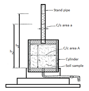
Fig: Falling head permeability test
- A cylinder containing the soil sample is placed on a base, i.e., a perforated disc, fitted with a fine gauze. The cylinder has a rubber stopper at top in which a graduated stand pipe is fitted.
- The test is conducted by filling the standpipe with de-aired water. It is allowed to flow through the soil sample.
- During the test, the water level in the stand pipe continuously drops and the height of the water in stand pipe is measured at several time intervals and it is then recorded. Any one pair of measurements can be used to calculate the coefficient of permeability from the following formula:
K = 
Where, a =area of c/s of stand pipe.
A =area of soil sample.
L = length of soil specimen
And h1, h2=heights of water measured in the stand pipe at time t1 and t2
If t2-t1 then
K = 2.3
- Several pairs of readings are used in this way and average of 4-5 values gives the average coefficient of permeability.
Key Takeaways:
This test is used to determine the permeability of fine-grained soils with very low permeability. Due to low permeability, the collected water will evaporate and will lead to wrong results in constant head test. Hence, this: test is used.
Field test for determination of permeability:
Pumping in test as per IS5529 Part-1:
- In pumping in test, an individualstrata through which hole is drilled, is considered so as to find the value of 'K’.
- Advantage pumping-in-test over the pumping out test:
- Pumping-in-test is more economic than pumping out test.
- It gives more reliable values than pumping-out-test.
- It gives the value of 'K' of strata very close to the hole but pumping-out-test gives the value of K for large area surrounded by the hole.
Generally, there are the types of pumping-in-test
- Open end test
- Packer test
Types of pumping-in-tests:
- Open-end test
- Packer tests:
a. Single packer test
b. Double packer test
1. Open-end test:
- In open-end test, a pipe casing is inserted into the hole of bore up to the required depth and then pipe casing is entirely cleaned out.
- Fig. Show the open-end test.
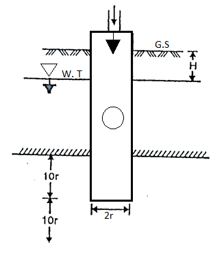
Fig: Open end test (constant discharge)
- At the time of cleaning, the hole is kept under water if it extends below the level of water table, which prevents the possibility of squeezing of the soil into the bottom of the pipe casing at the time of removing the driving tool.
- After cleaning the hole, hole is filled with water by a metering system. When the steady conditions are developed, that time the constant rate of flow or discharge (q) is found
- The coefficient of permeability is then found by the following expression.
K =
Where, K = coefficient of permeability
H = difference of level between the inlet of casing and water table
q = discharge
r= inner radius of pipe casing
- As per the requirements, the discharge 'q' can be increased by pumping-in water under pressure 'p' as shown in Fig. 2.6.6 and then the value of H becomes equal to (H+
 )
) - Note that for better results, the lower end of the pipe must be at a distance not less than 10r from the top and bottom of the strata.
- The open-end test can also carried out above W.T i.e., water table as shown in Fig.
- When this test is carried out above water table, it is very difficult to make up the constant water level in pipe casing and hence some surging of this vel has to be tolerated.
- (k=
 can also used in this case, However, H is equal to the difference of inlet level and the bottom end of the pipe.
 - As per the requirement, discharge can be increased by pumping in water under a pressure 'p' and that time total head becomes equal to (H+
 )
)
2. Packer test:
- The packer tests are carried out in an uncased portion of the pipe casing and it is commonly used for testing the rocks and sometime used for testing of soil provided the bore hole is open without any casing.
- There is the type of packer tests
(a)Single-packer tests
(b) Double-packer tests.
(a)Single-packer tests:
- This test is carried out under the situation when the hole cannot stand without a casing The packer is located as shown in Fig.
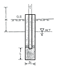
Fig: Single packer test (hole tested below W.T)
- Water is pumped into the hole then it comes out of the sides of uncased. Portion of the hole below the packer. For fel depth of casing: stratum should have perforations in its portions for testing. Lower end of the casing is closed by plug.
- Discharge 'q' found at steady condition. The value of K is determined by the following expressions. If L2 10r, then
K=
If 10r > L >r, then
K =
Where, K =coefficient of permeability
H = difference of water level at the entrance and the ground water table for the hole tested below W.T i.e., water table
r = inner radius of hole
 =are hyperbolic sine
- In Fig., if the hole is taken above the W.T i.e., water table for testing a H becomes equal to the difference of levels of water of the entry and middle of the test position.
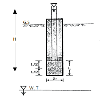
Fig: Single packer test (hole tested above W.T)
- In case of open-end tests, the value of H becomes equal to (H+
 )
) - Packer is removed after the completion of test. If again test to be performed, this hole is made deeper and a packer is placed.
(b)Double-packer-test:
- This test is performed under the situation that if the hole can stand without provision of casing.
- In this test, the hole is drilled to the final depth and then filed with water, surged as hailed out.
- Double-packer or two packers are used in this test and these two packers are fixed in the pipe as shown in Fig.
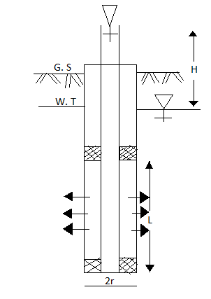
Fig: Double packer test (test section below W.T)
- The bottom of the pipe fixed with packers is closed by plug.
- In Fig. The section is below the water table (W.T) and in fig. The test section is above water table (W.T)
- The value of coefficient of permeability is determined by using following equations
- If L > 10r, then
K=
Or if 10r > L > r, then
K=
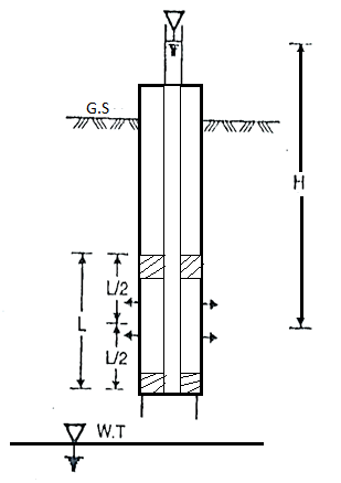
Fig: Double Packer test (test section above W.T)
Key Takeaways:
Types of pumping-in-tests are as follows:
1.Open-end test
2. Packer tests: Single packer test, Double packer test
Pumping out test as per IS5529 Part1:
- For determination of coefficient of permeability, the laboratory tests like constant head permeability and fall head permeability do not give the most accurate and correct results. The samples used in test are mostly disturbed and do not represents the true in-situ structure. Hence for getting good and correct results, the field tests are being carried out.
- In this test, the water is pumped out from the wells which is especially drilled for this purpose. This test is generally used in practice so as to measure the coefficient of permeability of soil for large engineering projects. For homogenous deposits and coarse-grained deposits this method is more suitable and useful because it is difficult to obtain undisturbed samples for this kind of deposits. This test is more expensive and hence used for bigger engineering projects.
- Ground water occurs in previous deposits known as aquifers which can be easily pumped out.
Unconfined aquifer
- If an aquifer does not have an aquiclude al top and the water table is in the aquifer itself, then it is called as unconfined aquifer.
Confined aquifer
- If the aquifer is confined between the aquicludes, one at its top and the other at its bottom them it is called as confined aquifer.
- The value of K i.e., coefficient of permeability of the soil can be determined by using equations for confined aquifer and unconfined aquifer separately.
(a) To find coefficient of permeability 'K' by using equations for unconfined aquifer:
- A tube well is drilled in case of unconfined aquifer till it reaches the underlying impervious strata.
- Perforated tube is used for the well so as the allow the water to enter in the well.
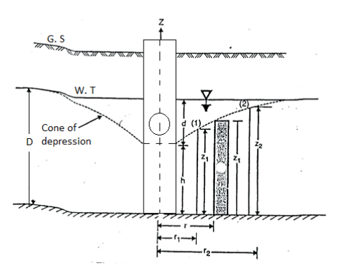
Fig: ‘K’ unconfined aquifer
- The complete tube is surrounded by strainer (screen) so as the identity the flow of soil particles into the well, water from the well is pumped out of the tube till a steady state is obtained. At the steady state, the discharge (4) becomes constant and water level in the tube remains unchanged. Because of pumping, the water near the well forms an inverted cone termed as the cone of depression and maximum depression of the water table is termed as draw-down (d),
Dupuit's Assumptions:
Derivation of 'K' can be obtained by following Dupuit's assumptions.
- Darcy's law is valid and flow is assumed to be laminar.
- Soil material is homogeneous as isotropic i.e., having equal elastic properties in all directions.
- The flow is assumed to be steady.
- The well penetrates the whole thickness of aquifer.
- Coefficient of permeability is assumed to be constant.
- The flow of water towards the well is horizontal and radial.
- The slope of the hydraulic gradient (i) line is small
i = 
8. Consider a flow through a cylindrical surface having height 'h' and at a radius distance 'r' from the centre of well.
q= KiA
K =coefficient of permeability
i = hydraulic gradient= dz/dr
A = total cross-sectional area of soil = 2 rz
rz
q=K )
) (2
(2
 =
= zdz
zdz
Integrating the above expression (2.9.1) for observation well I and 2, we get
 =
=
 k =
k = 
- Note that, there is a rapid drop in head near to the test well. Slope of the hydraulic gradient is steep hence, the assumption '7' is not satisfied.
- Wells I and2 should be drilled at considerable distance for observation so as to obtain accurate measurements. Rl is radial distance of the well should be at least equal to the thickness of aquifer having depth 'D'.
- The radius of influence varies between 150 m to 300m
- By Sichardt, R can be obtained as
R = 3000d √K
Where, R = radius of influence in m
K = coefficient of permeability 'm'/sec.
d=drawdown in 'm'
- By Kozeny, R can be obtained as
R = { )(
)( )1/2}1/2
Where, t= time required to establish steady conditions
n = porosity
- Equations (ii), can be written as
K =
Where, rw= radius of test well
R= radius of influence
D =depth of aquifer measured below the water table
h =depth of water in the well
Equation (iii) gives an approximate value of 'K' i.e., coefficient of permeability because the following reasons:
- Slope water surface near the well is steep.
- Dupuit's assumption is justified.
- Value of radius of influence (R) is approximate.
(b)To find 'K' by using equation for confined aquifer
- Let b thickness in confined aquifer lying between the two aquicludes. The water pressure is shown by the piezometric surface which is the above the top of the aquifer in confined aquifer. Note that piezometric surface and water table level is same for a confined aquifer.
- The piezometric surface (P.S) is horizontal in the beginning and once the pumping is started from the well, piezometric surface is depressed and finally a cone of depression is formed.
- Note that assumption which are used in case of unconfined aquifer are also used in case of confined aquifer for the purposed of derivation to find 'K’.
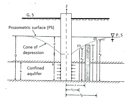
Fig: ‘K’ by confined aquifer
Let q discharge through cylindrical surface at a radial distance 'r' from the centre and z= height.
q=KiA ...by Darcy's law
q=K ( )(2
)(2 …...∴i=dz/dr and A=2
 rb
rb
 =
= (dz)
(dz)
Integrating the above equation, we get
∴K= 
Key Takeaways:
In this test, the water is pumped out from the wells which is especially drilled for this purpose. This test is generally used in practice so as to measure the coefficient of permeability of soil for large engineering projects.
Permeability depends on many factors. Following are the main factors that affect permeability:
Grain size:
- Grain size of the soil, or the effective size Dio is one of the factors which affect permeability. Allen Hazen gave the relation.
K = C(D10)2
Where, K Coefficient of permeability in cm/s and D10 is the effective grain size of the soil, C= constant (between 100 to 150)
- The permeability of coarse-grained soil is more than that of fine-grained soil
Properties of pore fluid:
- Permeability is directly proportional to the unit weight of pore fluid and inversely proportional to the viscosity of the pore fluid.
Temperature:
- Since viscosity of the pore fluid decreases with the temperature, permeability increases with temperature, as unit weight of the pore fluid does not change much with change in temperature.
Void ratio:
- Increase in void ratio increases the area available for flow, hence the permeability increases for critical conditions.
K e2
e2
Stratification of soil:
- Stratified soils are those, which are formed by layer upon layer of earth or dust deposited upon one another.
- If the flow is parallel to the layers or stratification, the permeability is maximum while the flow in perpendicular direction to the stratification occurs with minimum permeability.
Entrapped air and organic impurities:
- Organic impurities and entrapped air obstruct the flow and coefficient of permeability is reduced due to their presence.
Adsorbed water:
- Adsorbed water means a thin, microscopic film of water surrounding individual soil grains.
- This water is not free to move and hence reduces the effective pore space and thus decreases the coefficient of permeability.
Degree of saturation:
- The permeability of partially saturated soil is less than that of fully saturated soil.
Shape of particles:
- Permeability is inversely proportional to the specific surface e.g., the angular particles have more specific surface as compare to rounded particles. Therefore, the soil having angular particles is less permeable than soil of rounded particles.
Structure of soil mass:
- For same void ratio the permeability is more for flocculant structure as compare dispended structure.
Key Takeaways:
Factors affecting permeability are as follows:
- Grain size
- Properties of pore fluid
- Temperature
- Void ratio
- Stratification of soil
- Entrapped air and organic impurities
Natural pressure
The strain transmitted via way of means of the fluid that fills the voids among debris of a soil or rock mass; e.g., that a part of the entire regular strain in a saturated soil because of the presence of interstitial water. Synonym of: pore pressure, pore-water pressure, impartial pressure.
It is the strain or strain transmitted thru the pore fluid. It is likewise termed as pore strain and is denoted through u. In saturated soil, pores of the soil mass are full of water. When the saturated soil mass is loaded, the burden isn't always transmitted thru the grains. The load is transferred to the pore water. As water is incompressible, a strain is advanced within side the pore water.
Effective Pressure
Simply put, the impartial strain aircraft is the place inside a constructing wherein there's no distinction in strain among the internal and the outside. Its region inside a constructing is absolutely depending on the quantity of air leakage that takes place all through the structure.
Karl Terzaghi changed into the primary to understand the significance of powerful strain. It is the strain transmitted via grain to grain on the factor of touch via soil mass. It is likewise referred to as inter-granular strain. It is denoted via way of means of σ’.
When soil mass is loaded. The load is transferred to the soil profits via their factor of touch. If on the factor of touch, the carried out load is more than the resistance of the grains, then there could be compression within side the soil mass. This compression is in part because of the elastic compression of the grains on the factors of touch and in part because of relative sliding among particles. This load in keeping with unit region of soil mass accountable for deformation of the soil mass is called as powerful strain.
In many sensible cases, the character of the go with the drift thru soil is such that the rate and gradient range during the medium.
For those problems, calculation of go with the drift is normally made by use of graphs known as go with the drift nets.
The idea of go with the drift internet is primarily based totally on Laplace’s equation of continuity, which describes the consistent go with the drift circumstance for a given factor within side the soil mass.
In this newsletter we are able to talk approximately the Laplace equation for figuring out two-dimensional float of soil elements. Consider a soil detail of infinitesimally small length of dx and dz in X- and Z-directions, respectively, thru which the float is taking place, Consider unit duration of the soil detail within side the Y-direction.
Let vx be the velocity of flow at the entry in the X-direction and vz the velocity of flow at entry in the Z-direction. Then the velocity at the exit in the X-direction will be –

And the velocity at the exit in the Z-direction will be –

Quantity of water entering the element in the X-direction is given by –

Quantity of water entering the element in the Z-direction is given by –

Similarly, quantity of water leaving the soil element in the X-direction is –

Quantity of water leaving the soil element in the Z-direction is –

Assuming that the flow is steady and incompressible, the quantity of water entering the soil element is equal to the quantity of water leaving the soil element

Rearranging the terms, we have –

Dividing throughout with dz x dx, we have –

Let h be the total head at any point. Then the component of hydraulic gradient in the X-direction will be –
ix = – ∂h/∂x
The negative sign is to indicate that the head decreases in the direction of flow. Similarly, the component of hydraulic gradient in the Z-direction will be –
iz = ∂h/∂z
By Darcy’s law, we know that –
vx = kx .ix = – kx . ∂h/∂x
Similarly
vz = kz .iz = – kz . ∂h/∂x
Substituting these values in Eq. (10.19), we have –

Assuming that the soil mass is homogeneous, permeability will be same throughout in a given direction. Hence –

If the soil is isotropic, then kx = kz = k. Then, we have –

This is the Laplace equation for two-dimensional flow.
Various strategies of acquiring go with the drift nets are:
- Graphical method
- Electrical go with the drift Analogy method.
- Sand Model
- Capillary go with the drift Model.
- Solution of Laplace equation/Analytical method
1. Hydraulic models:
a. Streamlines may be traced through injecting a dye in a seepage version or Hele shaw apparatus.
b. They through drawing equipotential strains the waft internet is completed.
2. Analytical Method: a. It is most effective carried out to issues with easy and perfect limitations conditions. b. The equation corresponding curve ǿ and Ѱ are first received and the identical are plotted to provide the waft internet sample for the waft of fluid among the given boundary shape.
Analytical approach of acquiring a float internet for a float of water in a soil mass is a mathematical method to an equation this is acquired with the aid of using the float situations. It may be utilized in exceptionally easy instances of float, wherein the boundary situations are acknowledged and may be expressed with the aid of using equations. Let’s don't forget a soil mass that's absolutely saturated with the aid of using water flowing via it. We count on speed of flowing water in x and z instructions are Vx and Vz respectively.
3. Electrical Analogy Method:
This approach primarily based totally at the reality that the waft of fluids and waft of strength via a conductor are analogue. These structures are comparable within side the recognize that electric powered ability is analogue to the rate ability. The electric powered contemporary is analogue to the rate of waft and the homogeneous conductor is analogue to the homogeneous fluid. This approach most effective for a realistic approach of drawing a waft internet for a specific set of limitations
4. Graphical Method:
This approach calls for a variety of erasing to get the right form of a float internet and additionally devour a plenty of time. A graphical includes drawing steam lines and equipotential traces such that they reduce orthogonally and shape curvilinear squares.
This is the maximum generally used approach of float internet production as it is straightforward and it affords almost correct results. This approach is one of the answers to the Laplace equation. Let us recognize this approach via way of means of drawing a float internet for a hydraulic condition. Let's take a soil mass of a few thickness and it lies upon an impermeable strata. A sheet pile is pushed into the soil as much as a few intensity.
The sheet has water on its one aspect of intensity capital D and on some other aspect small d. We can see there's imbalance of head at the one of a kind aspect of the sheet pile, so water will float from excessive head to low head. But water cannot by skip thru this sheet pile so float will take vicinity thru seepage thru soil below.
Key takeaways:
This is the maximum generally used approach of float internet production as it is straight forward and it affords almost correct results. This approach is one of the answers to the Laplace equation.
A Flow internet is a graphical illustration of glide of water via a soil mass. It is a curvilinear internet fashioned via way of means of the mixture of glide strains and equipotential strains. Properties and alertness of glide internet are defined on this article.
Flow strains constitute the direction of waft alongside which the water will seep thru the soil. Equipotential strains are fashioned with the aid of using connecting the factors of same overall head.
Properties of go with the drift internet are as follows: The attitude of intersection among every go with the drift line and an equipotential line should be 90o because of this that they ought to be orthogonal to every other. Two go with the drift strains or equipotential strains can in no way pass every other. Equal amount of seepage happens in every go with the drift channel.
A go with the drift channel is a area among go with the drift strains. Head loss is the identical among adjoining ability strains. Flow nets are drawn primarily based totally at the boundary situations only. They are impartial of the permeability of soil and the pinnacle inflicting go with the drift. The area shaped among go with the drift strains and equipotential strains is referred to as a go with the drift field. It ought to be in a rectangular form. Either go with the drift strains or equipotential strains are easily drawn curves.
Flow internet is beneficial to decide the subsequent parameters in seepage evaluation of soil: Rate of Seepage loss Seepage Pressure Uplift Pressure Exit Gradient
Rate of Seepage loss (Q)
Using glide internet, the price of seepage loss or seepage amount may be decided the usage of the underneath expression:

Seepage loss price Where,
K= Coefficient of permeability
Seepage Pressure (Ps)
Seepage stress at any factor is decided through the use of the under cited formula:


Uplift Pressure (Pu)
The uplift strain at any factor in the soil mass may be discovered the use of the under mentioned formula. It is likewise known as hydrostatic strain.

Where
 = unit weight of water
 = piezometric head or pressure head = total head-elevation head

Exit Gradient (I exit)
The go out gradient is the hydraulic gradient on the downstream give up of waft line in which seepage water from the soil mass joins with unfastened water on the downstream. Exit gradient may be expressed as:

Where,
 =potential drop
 =lengthoftheflowfield
Key takeaways:
The go out gradient is the hydraulic gradient on the downstream give up of waft line in which seepage water from the soil mass joins with unfastened water on the downstream.
- ABC is a sheet pile driven in pervious layer of depth d, the depth of embedment BC being d' Fig.
- UB and TV are potential boundaries with known heads. BCST and xy are flow line boundaries because these are impervious surface across which water cannot pass.
- Flow lines will emerge at right angles from UB and end at right angles at TV. Because of symmetry flow not will symmetrical, about vertical axis.
Procedural steps:
- Make a scale drawing showing the structure, soil mass, the pervious boundaries and the impervious boundaries.
- Sketch the first trial flow line as f1 f1 Emerging at right angles at UB running round the sheet pile and meeting TV at right angles.
- Sketch the first equipotential line p1 p1so as to make a square figure with the flow line f1 f1 and the boundary BC and ending at right angles to the boundary flow line, Now sketch the second flow line f2 f2 again emerging at right angles with UB making square figure with P, P, going round the sheet pile parallel to the first line f1 f1 and ending at right angles to TV.
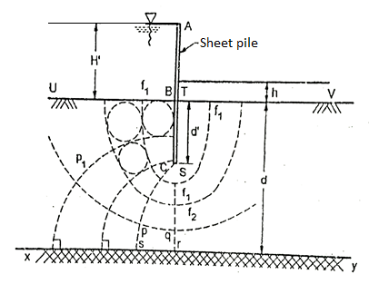
Fig: Flow net for sheet pile
4. Then sketch the next trial potential line, emerging at right angles from BC, making square figures with neighboring flow lines and meeting xy at a right angle. Continue sketching to complete the flow net.
5. Now, check (by drawing circles touching all the sides of the square) the square figures and orthogonality everywhere in the flow net. The first attempt can hardly produce a good flow net. Make a second, third and if required more attempts, till a reasonably good flow net has been sketched.
Key takeaways:
- UB and TV are potential boundaries with known heads. BCST and xy are flow line boundaries because these are impervious surface across which water cannot pass.
- Flow lines will emerge at right angles from UB and end at right angles at TV. Because of symmetry flow not will symmetrical, about vertical axis.
Soil consolidation refers back to the mechanical method with the aid of using which soil modifications quantity steadily in reaction to a extrude in strain. This takes place due to the fact soil is a two-segment material, comprising soil grains and pore fluid, commonly groundwater. When soil saturated with water is subjected to an growth in strain, the excessive volumetric stiffness of water as compared to the soil matrix approach that the water to begin with absorbs all of the extrude in strain without converting quantity, developing extra pore water strain.
As water diffuses far from areas of excessive strain because of seepage, the soil matrix steadily takes up the strain extrude and shrinks in quantity. The theoretical framework of consolidation is consequently carefully associated with the diffusion equation, the idea of powerful pressure, and hydraulic conductivity. In the slender sense, "consolidation" refers strictly to this behind schedule volumetric reaction to strain extrude because of sluggish motion of water. Some guides additionally use "consolidation" within side the huge sense, to consult any method with the aid of using which soil modifications quantity because of a extrude in implemented strain.
This broader definition encompasses the general idea of soil compaction, subsidence, and heave. Some styles of soil, especially the ones wealthy in natural matter, display full-size creep, wherein the soil modifications quantity slowly at regular powerful pressure over an extended time-scale than consolidation because of the diffusion of water. To distinguish among the 2 mechanisms, "number one consolidation" refers to consolidation because of dissipation of extra water strain, while "secondary consolidation" refers back to the creep method. The outcomes of consolidation are maximum conspicuous in which a constructing sits over a layer of soil with low stiffness and occasional permeability, inclusive of marine clay, main to huge agreement over many years. Types of creation challenge in which consolidation regularly poses technical threat encompass land reclamation, the development of embankments, and tunnel and basement excavation in clay. Geotechnical engineers use odometers to quantify the outcomes of consolidation. In an odometer test, a chain of acknowledged pressures are implemented to a skinny disc of soil pattern, and the extrude of pattern thickness with time is recorded. This lets in the consolidation traits of the soil to be quantified in phrases of the coefficient of consolidation (}C_}) and hydraulic conductivity (K).
Consolidation is the manner wherein discount in quantity takes vicinity via way of means of the sluggish expulsion or absorption of water beneath long-time period static loads. When strain is implemented to a soil, it reasons the soil debris to % collectively greater tightly. When this takes place in a soil this is saturated with water, water may be squeezed out of the soil. The value of consolidation may be expected via way of means of many one of a kind methods. In the classical approach evolved via way of means of Terzaghi, soils are examined with an odometer check to decide their compressibility. In maximum theoretical formulations, a logarithmic courting is thought among the quantity of the soil pattern and the powerful strain carried via way of means of the soil debris. The steady of proportionality (extrude in void ratio according to order of value extrude in powerful strain) is referred to as the compression index, given the symbol lambda while calculated in herbal logarithm and }} while calculated in base-10 logarithm
Key takeaways:
Consolidation is the manner wherein discount in quantity takes vicinity via way of means of the sluggish expulsion or absorption of water beneath long-time period static loads. When strain is implemented to a soil, it reasons the soil debris to % collectively greater tightly.
Shear energy parameters, consisting of the concord and the attitude of shear energy, are key parameters to characterise the failure of materials. These parameters may be decided thru at the least triaxial assessments through plotting the Mohr circles related to the imposed shearing strain path (e.g. Traditional triaxial compression) and through regarding the slope (i.e. the attitude of shear energy) and the intercept with the ordinate axis of the tangent line to the circles. From a realistic attitude the shear energy parameters of soils (e.g. Beneath steady extent conditions) may be taken into consideration unbiased of temperature as regards to the temperature versions related to the geothermal operation of electricity geo structures.
Mohr-coulomb energy parameters Stability evaluation of a rock slope calls for evaluation of shear energy parameters, that is, cohesion (c) and perspective of inner friction (ϕ) of the rock mass. Estimates of those parameters are normally now no longer primarily based totally on sizeable area assessments. Mehrotra (1992) finished sizeable block shear assessments to look at the shear energy parameters of rock masses. The following inferences can be drawn from this look at: 1. The rock mass rating (RMR) device may be used to estimate the shear energy parameters c and ϕ of the weathered and saturated rock masses. It became located that the cohesion (c) and the perspective of inner friction (ϕ) growth while RMR growth
The impact of saturation on shear electricity parameters has been located to be significant. For bad saturated (wet) rock masses, a most discount of 70% has been found in cohesion (c), while the discount in attitude of inner friction (ϕ) is of the order of 35% whilst in comparison to the ones for the dry rock masses. Suggests that there may be a non-linear version of the attitude of inner friction with RMR for dry rock masses This take a look at additionally suggests that ϕ values of Bieniawski (1989) are particularly conservative.
Shear power parameters not directly permit figuring out the shaft and base contributions of feature floor resisting load, and via suitable ability formulations. Because the floor is the fabric that absorbs all of the moves via the pile, the choice of feature values for geotechnical parameters shall take account of the following (EN 1997, 2004):
Geological and different historical past information, including information from preceding projects;
Variability of the measured belongings values and different applicable information, for instance from current knowledge
Extent of the sector and laboratory investigation
Type and wide variety of samples
Extent of the area of floor governing the behaviour of the geotechnical shape
Limit nation being considered
Ability of the geotechnical shape to switch masses from susceptible to sturdy zones within side the floor
To attain the layout fee of floor resisting load thru the existing approach, partial elements can be carried out both to the feature floor properties , to the feature resisting masses or to both. Two units of endorsed partial elements for floor parameters are suggested in Table 15.five almost about the EN 1997 (2004).
Key takeaways:
Shear power parameters not directly permit figuring out the shaft and base contributions of feature floor resisting load, and via suitable ability formulations.
Liquefaction is a phenomenon wherein the power and stiffness of a soil is decreased through earthquake shaking or different fast loading. Liquefaction takes place in saturated soils, that is, soils wherein the distance among character debris is absolutely full of water.
Soil liquefaction takes place whilst a saturated or partly saturated soil extensively loses electricity and stiffness in reaction to an implemented strain consisting of shaking for the duration of an earthquake or different unexpected extrude in strain circumstance, wherein fabric this is usually a strong behaves like a liquid. In soil mechanics, the term "liquefied" became first utilized by Allen Hazen in connection with the 1918 failure of the Clavers Dam in California. He defined the mechanism of go with the drift liquefaction of the embankment dam as: If the strain of the water within side the pores is first rate sufficient to hold all of the load, it's going to have the impact of protecting the debris aside and of manufacturing a circumstance this is almost equal to that of quicksand the preliminary motion of a few a part of the fabric may bring about amassing strain, first on one point, after which on another, successively, because the early factors of attention have been liquefied.
The phenomenon is most usually determined in saturated, unfastened (low density or un compacted), sandy soils. This is due to the fact a unfastened sand has a bent to compress whilst a load is implemented. Dense sands, via way of means of contrast, generally tend to amplify in quantity or 'dilate'. If the soil is saturated via way of means of water, a circumstance that frequently exists whilst the soil is beneath the water desk or sea level, then water fills the gaps among soil grains ('pore spaces'). In reaction to soil compressing, the pore water strain will increase and the water tries to go with the drift out from the soil to zones of low strain (normally upward toward the floor). However, if the loading is swiftly implemented and huge sufficient, or is repeated many times (e.g. earthquake shaking, hurricane wave loading) such that the water does now no longer go with the drift out earlier than the following cycle of load is implemented, the water pressures might also additionally construct to the quantity that it exceeds the force (touch stresses) among the grains of soil that maintain them in touch.
These contacts among grains are the approach via way of means of which the burden from homes and overlying soil layers is transferred from the floor to layers of soil or rock at more depths. This lack of soil shape reasons it to lose its electricity (the capacity to switch shear strain), and it is able to be determined to go with the drift like a liquid (hence 'liquefaction'). Although the results of soil liquefaction had been lengthy understood, engineers took extra word after the 1964 Alaska earthquake and 1964 Niigata earthquake. It became a primary component within side the destruction in San Francisco's Marina District for the duration of the 1989 Loma Pieta earthquake, and within side the Port of Kobe for the duration of the 1995 Great Hanshin earthquake.
More these days soil liquefaction became in large part accountable for considerable harm to residential houses within side the jap suburbs and satellite for pc townships of Christchurch, New Zealand for the duration of the 2010 Canterbury earthquake and extra significantly once more following the Christchurch earthquakes that observed in early and mid-2011. On 28 September 2018, an earthquake of 7.five value hit the Central Sulawesi province of Indonesia. Resulting soil liquefaction buried the suburb of Balaroa and Petobo village in three meters deep mud. The authorities of Indonesia is thinking about designating the 2 neighbourhoods of Balaroa and Petobo, which have been absolutely buried below mud, as mass graves The constructing codes in many nations require engineers to bear in mind the results of soil liquefaction within side the layout of latest homes and infrastructure consisting of bridges, embankment dams and preserving structures.
Soil liquefaction takes place whilst the powerful pressure (shear power) of soil is decreased to basically 0. This can be initiated via way of means of both monotonic loading (i.e. a single, surprising incidence of a extrude in pressure – examples consist of an boom in load on an embankment or surprising lack of toe support) or cyclic loading (i.e. repeated modifications in pressure condition – examples consist of wave loading or earthquake shaking). In each instances a soil in a saturated unfastened country, and one that may also generate widespread pore water strain on a extrude in load are the maximum possibly to liquefy. This is due to the fact unfastened soil has the tendency to compress whilst sheared, producing massive extra pore water strain as load is transferred from the soil skeleton to adjoining pore water at some point of un drained loading. As pore water strain rises, a modern lack of power of the soil takes place as powerful pressure is decreased. Liquefaction is much more likely to arise in sandy or non-plastic salty soils, however may also in uncommon instances arise in gravels and clays (see short clay).
A 'waft failure' may also provoke if the power of the soil is decreased under the stresses required to preserve the equilibrium of a slope or footing of a structure. This can arise because of monotonic loading or cyclic loading, and may be surprising and catastrophic. A historic instance is the Aberfan disaster. Casagrande stated this form of phenomena as 'waft liquefaction' even though a country of 0 powerful pressure isn't required for this to arise. 'Cyclic liquefaction' is the country of soil whilst massive shear lines have amassed in reaction to cyclic loading. A traditional reference pressure for the approximate incidence of 0 powerful pressure is 5% double amplitude shear pressure.
This is a soil test-primarily based totally definition, normally carried out thru cyclic triaxial, cyclic direct easy shear, or cyclic torsional shear kind apparatus. These checks are carried out to decide a soil's resistance to liquefaction via way of means of staring at the quantity of cycles of loading at a selected shear pressure amplitude required to induce 'fails'. Failure right here is described via way of means of the aforementioned shear pressure criteria. The term 'cyclic mobility' refers back to the mechanism of modern discount of powerful pressure because of cyclic loading. This may also arise in all soil kinds together with dense soils. However, on accomplishing a country of 0 powerful pressure such soils straight away dilate and regain power. Thus, shear lines are considerably much less than a real country of soil liquefaction
Key takeaways:
Soil liquefaction takes place whilst the powerful pressure (shear power) of soil is decreased to basically 0. This can be initiated via way of means of both monotonic loading
References:
1. Physical and Geotechnical Properties of Soils by Joseph E. Bowles, International Students Edition.
2. Principles of Geotechnical Engineering by Braj M. Das, Cengage Learning.
3. Geotechnical Engineering by P.Purushothma Raj, Tata Mc GrawHill.
4. Geotechnical Engineering by Principles & Practices by Donald. P. Coduto, Pearson Education.
5. Basic and Applied Soil Mechanics by Gopal Ranjan and A. S. R. Rao, New age International.