Unit - 3
Plane Table Surveying
This is the fast method of surveying. In this type of surveying plotting of the plan and field observations can be done parallel. In case of plane table surveying Geometrical conditions of site are manuscript in the map sheet using plane table and alidade after that topographic details are arranged on the map.
Equipment Used in Plane Table Survey
General equipment used for conducting plane table survey are
- Plane table
- Alidade for sighting (telescopic or simple)
- Plumb bob and plumb fork
- Compass
- Spirit level
- Chain
- Ranging rods
- Tripod
- Drawing sheet and drawing tools
- Paper clips or screws
Plane table survey equipment is arranged in 4 steps as follows
- Fixing of Plane Table
Fix the plane table to the tripod stand. Arrange the drawing sheet on the plane table using paper clips or thumb screws. The sheet should be in one position from first to last.
II. Levelling of Plane Table
Plane table can be levelled using spirit level. For small works, eye estimation can be ok.
III. Cantering of Plane Table
The table should be cantered by using plumbing fork from which we can arrange the plotted point exactly over the ground point.
IV. Orientation of Plane Table
Whenever we are using more than one instrument station, orientation is necessary. It can be done by using compass or back sighting. Here the plane table is rotated such that plotted lines in the drawing sheet are parallel to corresponding lines on the ground.
Key takeaways:
The table should be cantered by using plumbing fork from which we can arrange the plotted point exactly over the ground point.
Plane desk surveying is primarily based totally at the precept that traces drawn at some point of plotting constantly lie parallel to the corresponding traces truly gift at the floor i.e the precept of aircraft desk surveying is parallelism.
The regulation of aircraft tabling is parallelism, which means the rays drawn from stations to objects at the paper are parallel to the traces within side the stations to the gadgets at the floor. The relative positions of those gadgets at the floor are represented with their very own plotted positions approximately the paper and lie at the respective rays. The desk is constantly positioned at every of the successive stations parallel into the location it occupied within side the beginning station. Plane tabling is a graphical manner of surveying.
The fieldwork and plotting are finished simultaneously, and this survey doesn’t contain the use of a area book(dimension book). Plane desk survey is particularly appropriate for filling insider info while traversing is finished with the theodolite. Sometimes traversing with a aircraft desk may additionally be finished. However, this survey is suggested for the paintings in which brilliant accuracy isn’t required. As the solving and becoming association of this tool isn't perfect, maximum correct paintings can't be expected.
The only and the maximum usually used aircraft desk is as proven in as in keeping with underneath figure. It is referred to as a traverse desk. It includes a board made from a well-pro wooden set up a mild tripod with appropriate mounting and clamping devices. The board can rotate approximately a vertical axis and may be clamped in any position. The desk is to be leveled with the aid of using adjusting the tripod.
Plane Table Survey Instruments: Alidade or Sight Rule Plumbing Fork with Plumb Bob Spirit Level Trough Compass Drawing Sheet and Miscellaneous Accessories for Drawing. Alidade or Aright Rule An alidade is a straight-facet ruler the usage of a few shape of sighting device. One gain of this ruler is a beveled facet that’s is likewise called the fiducially facet. This gain is graduated and used for drawing no line of sights. Based at the sort of line of sight Provided, there are forms of alidade: Plain Alidade Telescopic
Alidade Plain Alidade : In the case of the apparent alidade, a sight vane at every cease of the ruler is supplied, as proven in as consistent with under discern (Ref. As consistent with above discern also). Among that sight, vanes are supplied with a slim slit, and it serves as eye vane. Another sight vane called element vane is wider and it includes horsehair or a skinny twine in its center
Key takeaways:
The table should be cantered by using plumbing fork from which we can arrange the plotted point exactly over the ground point.
Methods of Plane Table Surveying:
Generally, there are four methods available to perform plane table surveying. They are
- Radiation
- Intersection
- Traversing
- Resection
Radiation
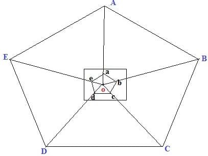
In this method, plane table is located at one point “o” and perform the whole from that point. From point O, sight the points A, B,C,D and E using alidade, locate and plot the points as a,b,c,d and e in the drawing sheet.
Intersection
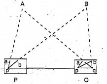
In this method we can locate the point by plotting two rays from two known stations. As shown in figure, P and Q are the known station. First the equipment is placed on P and plot the lines by sighting the stations A, B and Q. Then shift the equipment to station Q and plot the lines by sighting stations A, B and P. Finally, the intersection of A and B rays is the required location of point of intersection.
Traversing
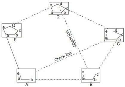
Traversing is the connection of series of straight lines. In case of traversing, plane table is located at one-point A as shown below. From here point sight towards B and measure the distance AB.
Then shift the plane table to point B and sight towards A and measure BA. Average distance of AB and Ba are plotted to scale in drawing sheet. Then Sight the point C from B and measure BC and repeat the same procedure until last point. Conduct some checks at some points. Finally, traverse lines are plotted on drawing sheet.
Resection
Resection is a method of plane table surveying in which location of plane table is not known and it is determined by sighting it to known points or plotted points. It is also called method of orientation and it can be conducted by two field conditions which are:
- The three-point problem
- The two-point problem
Key takeaways:
Resection is a method of plane table surveying in which location of plane table is not known and it is determined by sighting it to known points or plotted points. It is also called method of orientation and it can be conducted by two field conditions which are:
There are following types of Errors in Levelling: -
- Instrumental Errors
- Collimation Error
- Error due to Curvature & Refraction
- Other Errors
1. Instrumental error and Correction
- Collimation error
- Correction: Check before use and equalise sights.
- Under sensitive bubble.
- Errors in staff graduation
- Correction: Check
- Loose tripod head.
- Telescope not parallel to bubble tube
- Correction: Permanent adjustment.
- Telescope not at right angles to the vertical axis
- Correction: Permanent adjustment
2. Error of Collimation
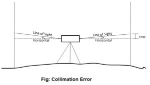
Collimation error occurs when the collimation axis is not truly horizontal when the instrument is level. The effect is illustrated in the sketch below, where the collimation axis is tilted with respect to the horizontal by an angle a.
3. Curvature & Refraction
Curvature of the earth:
The earth appears to “fall away” with distance. The curved shape of the earth means that the level surface through the telescope will depart from the horizontal plane through the telescope as the line-of-sight proceeds to the horizon.
This effect makes actual level rod readings too large by:

Where D is the sight distance in thousands of feet.
Effects of Curvature are:
- Rod reading is too high
- Error increases exponentially with distance
Atmospheric Refraction:
Refraction is largely a function of atmospheric pressure and temperature gradients, which may cause:
The bending to be up or down by extremely variable amounts.
The atmosphere refracts the horizontal line of sight downward, making the level rod reading smaller. The typical effect of refraction is equal to about 14% of the effect of earth curvature.
Combined Effect of Curvature and Refraction in Survey
The combined effect of curvature and refraction is approximately

The formula for computing the combined effect of curvature and refraction is:
C + R = 0.021K2
Where C = correction for curvature
R = correction for refraction
K = sighting distance in thousands of feet
5. Other sources of errors in levelling and their correction:
Type of Error | Correction |
1. Incorrect setting-up of instrument. |
|
2. Movement of staff from position when changing level station. |
|
3. Staff not held vertically. |
|
4. Parallax: Instrument knocked or moved during backsight-foresight reading |
|
5. Ground heating causes chaotic refraction of light |
|
6. Tripod or rod settles between measurements e.g., Bubble off center |
|
Key takeaways:
Collimation error occurs when the collimation axis is not truly horizontal when the instrument is level. The effect is illustrated in the sketch below, where the collimation axis is tilted with respect to the horizontal by an angle a.
Three Point Problem
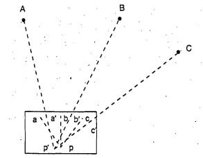
Three points and their positions in the field are known. Plane table is placed at a position from where all the three points are visible. So, by sighting those three points we can locate the point where equipment is located. This can be achieved by following methods
- Tracing method
- Lehmann method
- Analytical methods
- Graphical method
Tracing Method in Plane Table Surveying
Here plane table is located at a point from where three points are visible. The table is oriented with respect to the plotted lines of those three points. Place the tracing paper on the drawing sheet and again sight the three points and plot the radiating lines. The tracing paper is then moved above the drawing sheet until the three radiating lines pass through corresponding points previously plotted on the map and then the position of plane table is marked
Lehmann Method
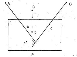
Here the Plane table is located at a point P and sight the station A, B and C and plot the rays Aa, Bb, and Cc. The rays form small triangle are called triangle of error. Another point P1 is chosen to reduce the error and sight the point A from P1 similarly to B and C. Which will give another triangle of error. Repeat this procedure until error becomes 0.
Analytical Methods
There are many analytical methods are developed in three-point problem condition. In this method, from station P A, B and C are sighted and the values of angles and lengths are noted.
Graphical Method
In these angles and lengths are determined and represented it on a graph which determines the location of plane table.
The Two-Point Problem
In the two-point problem, two points are sighted from other point corresponding to the points given in plane table sheet. Here two cases are to be discussed.
Case 1: when the points can be occupied by the plane table
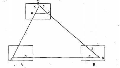
As shown in fig. A and B are the two points corresponding to the points a and b. Now, plane table is located at B and oriented by sighting A. Sight C from B and bx is plotted on the sheet. Then shift the plane table to C, oriented by back sighting B along xb. Then alidade is placed over a and sight station A, then line Aa cuts the line bx at somewhere which is located as point c at station C.
Case2: When the plane table cannot occupy the controlling stations
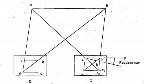
In this case, an auxiliary point D is considered nearer to C. Locate the plane table at D according to the line ab parallel to AB. Then sight the station A and B corresponding to a and b. The rays drawn are intersected at some point which is marked as d. Then sight towards C by placing alidade at d. Mark the distance Dc as c1. Shift the table to C and back sight to D with reference to c1.
Then sight A corresponding to a, the ray drawn is intersects the previously drawn ray from D in c2. From c2 sight B draw a ray which intersects db and marked the intersection as b1. The table is oriented till ab comes in line with P. From P sight and draw rays Aa and Ba. The intersection of these two rays will give the Location of Point C.
Surveying based on Type of Instruments
a) Chain Surveying
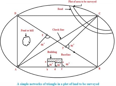
Chain surveying is the basic type of surveying. The principle involved in chain survey is of triangulation. The area to be surveyed is divided into a number of small triangles. Angles of triangles must not be less than 30 degree and greater than 120 degree. Equilateral triangles are known to be ideal triangles. No angular measurements are taken, tie line and check lines control accuracy of the work.
This method is suitable on level ground with little undulations and area to be survey is small.
b) Compass Surveying
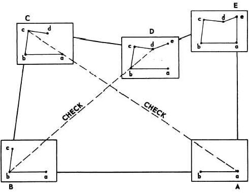
Compass survey uses the principle of traversing. This method does not require the need to create triangles. It uses a prismatic compass for measuring magnetic bearing of line and the distance is measured by chain. A series of connecting lines is prepared using compass and measuring distances using chain. Interior details are located using offset from main survey lines.
They suitable for large area surveying crowded with many details. It can be used to survey a river course.
c) Plane Table Surveying
The principle of plane table survey is parallelism. They are plotted directly on paper with their relative position. The rays are drawn from station to object on ground. The table is placed at each of the successive station parallel to the position of the last station.
They are basically suitable for filling interior detailing and is recommended when great precision is not required.
d) Theodolite Surveying
The theodolite is an instrument used mainly for accurate measurement of the horizontal and vertical angles. They are accurate to measure up to 10″ or 20″ angles.
Theodolite can be used to measure:
- Horizontal angles
- Vertical angles
- Deflection angle
- Magnetic bearing
- Horizontal distance between two points
- Vertical height between two points
- Difference in elevation
Nowadays theodolite is shadowed and replaced by the use of Total Station which can perform the same task with greater ease and accurate results
e) Tachometric Surveying
Tachometry is a branch of surveying in which horizontal and vertical distances are determined by taking angular observations with an instrument called tacheometer. Tacheometer is nothing but a transit theodolite fitted with a stadia diaphragm and an analytic lens. There is no need for chaining in such survey. The principle of Tacheometer is based on property of isosceles triangle, where ratio of the distance of the base from the apex and the length of the base is always same.
Different form of stadia diaphragms commonly used:

f) Photographic Surveying
Photographic survey is based on technique of taking photographs from different angle to prepare topographic details with relative high speed.
There are two types of photographic surveying
i). Terrestrial or ground photogrammetry
In terrestrial photogrammetry maps are prepared from ground photographs from different points on the earth surface for measurement purpose.
Ii). Aerial photogrammetry
In aerial photogrammetry maps are produced from air from an airplane or helicopter.
Photogrammetry encompasses two major area of specialization.
- Metrical photogrammetry
- Interpretive photogrammetry
Metrical photogrammetry is of principal interest to surveyors as it is applied to determine distances, elevations, areas, volume, etc. to compile topographic maps made from measurements on photographs.
Intuitive photogrammetry involves objects from their photographic image and their significance. Critical factors considered in identifying object of shape, sizes, patterns, shadow.
Key takeaways:
Three points and their positions in the field are known. Plane table is placed at a position from where all the three points are visible.
References:
1. Duggal, S.K. Surveying Vol. I and II, Tata McGraw Hill, 2004.
2. Punmia, B.C. Surveying Vol. I and II, Standard Publishers, 1994.
3. Arora, K. R. Surveying Vol. I and II, Standard Book House, 1996
4 N.N Basak. Surveying and levelling