Unit - 4
Leveling
Leveling may be defined as the art of determining the relative height or elevates of points or objects on the earth’s surface.
Instruments used for leveling:
Level
Leveling Staff
Level: The purpose of a level is to provide a horizontal line of sight.
Parts:
A telescope to provide line of sight
A level tube to make the line of sight horizontal
Leveling head to bring the bubble in its centre of run
A tripod to support the instrument
Dumpy level:
The telescope is fixed with the support and therefore, can neither be rotated about the longitudinal axis, or can it be removed from its support. A long bubble tube is attached at the top of the telescope. The levelling head generally consists of two parallel plates with either three-foot screw of four-foot screws. The upper plate is known as tribrach and the lower plate is known as trivet which can be screwed on a tripod.
Leveling staff:
- A levelling Staff is a straight rectangular rod having graduations, the foot of the staff representing zero reading.
- One is Folding type of 4m Levelling Staff:
- It consists of two wooden pieces each of 2m of length with the joint assembly. The thickness and width of staff are respectively 18m and 75mm. The folding joint is of the detachable type with locking device at the back.
- Hence the stand can be made into two parts for easy handling. When two pieces are locked together, the two pieces form a straight rigid levelling staff of length equal to 4m.
- When the level is set up correctly and levelled the line of collimation will be horizontal telescope is rotated about is its vertical axis the it will revolve in a horizontal plane known as the plane of collimation and therefore, all staff’s readings taken with the will be the vertical measurements made downwards from this plane.
- To find by how much amount the line of sight is above the bench mark and to ascertain by how much amount the next point is below or above the line sight.
- Height of instrument= Elevation of B.M + Back sight Elevation of pt B = Height of instrument – Foresight
- There are two methods of working out the reduced levels of the point from the staff readings taken in the field:
- 1. Height of Instrument or Collimation Method.
- 2. Rise and Fall Method.
1. Height of Instrument or Collimation Method.
- It helps in finding the elevation of the plane of collimation i.e. (H.I.) for every setting of the instrument and then getting the reduced levels of the points with reference to the respective plan of collimation
- To start with, the H.L is calculated by adding the back sight of the R.L. Of the starting point. The reduced levels of the intermediate point and the first change point are then obtained by subtracting the respective readings from the H.I. When the instrument is shifted, a new plane of collimation is set up and the height of which is calculated by adding back sight reading to the R.L. Of the first change point.
Key takeaways:
It helps in finding the elevation of the plane of collimation i.e. (H.I.) for every setting of the instrument and then getting the reduced levels of the points with reference to the respective plan of collimation
Simple Leveling
It is a easy and primary shape of leveling wherein the leveling tool is positioned among the factors which elevation is to be find. Leveling rods are positioned at that factors and sighted them via leveling tool. It is completed handiest while the factors are closer to every different with none obstacles
Differential Leveling
Differential leveling is completed while the distance among factors is more. In this process, range of inter stations are placed and tool is shifted to every station and discovered the elevation of inter station factors. Finally distinction among authentic factors is determined Fly Leveling The levelling operation wherein handiest BS and FS readings are taken and no intermediate points of interest are discovered is known as fly levelling. It is completed for connecting the benchmark to the start line of any project. In such levelling, no horizontal distances are required to be measured.
Profile Leveling
Profile leveling is commonly followed to locate elevation of factors alongside a line including for road, rails or rivers etc. In this case, readings of intermediate stations are taken and decreased degree of every station is found. From this cross phase of the alignment is drawn.
Reciprocal Leveling
When it isn't always viable to find the leveling tool in among the inter seen factors, reciprocal leveling is performed. This case seems in case of ponds or rivers etc. in case of reciprocal leveling, tool is set closer to 1st station and sighted in the direction of second station. Trigonometric Leveling The system of leveling wherein the elevation of factor or the distinction among factors is measured from the observed horizontal distances and vertical angles within side the field .In this method, trigonometric members of the family are used to locate the elevation of a factor from attitude and horizontal distance
Barometric Leveling
Barometer is a device used to degree atmosphere at any altitude. So, on this technique of leveling, atmospheric stress at distinctive factors is observed, primarily based totally on which the vertical difference among factors is determined. It is a rough estimation and used rarely. Stadia Leveling It is a changed shape of trigonometric leveling wherein Tachometer precept is used to decide the elevation of point. In this case the road of sight is willing from the horizontal. It is greater correct and appropriate for surveying in hilly terrains.
Differential Levelling
Establishing elevations is the most essential activity of the field engineer. Elevations are needed to set slope stakes, grade stakes, footings, anchor bolts, slabs, decks, sidewalks, curbs, etc.
Differential levelling is a very simple process based on the measurement of vertical distances from a horizontal line. Elevations are transferred from one point to another through the process of using a levelling instrument to read a rod held vertically on, first, a point of known elevation and, then, on the point of unknown elevation. Simple addition and subtraction are used to calculate the unknown elevations.

A back-sight reading is taken on a rod held on a point of known elevation. That elevation is transferred vertically to the line of sight by reading the rod and then adding the known elevation and the back sight reading. The elevation of the line of sight is the height of instrument (HI), the line of sight is horizontal; therefore, the line-of-sight elevation can then be transferred down to the unknown elevation point by turning the telescope to the foresight and reading the rod. The elevation of the foresight station is found by subtracting the rod reading from the height of instrument. The difference in elevation from the back sight station to the foresight station is determined by subtracting the foresight rod reading from the back sight rod reading.
Reciprocal levelling
If the level is placed exactly midway between two points and staff reading are taken to determine the difference of level then an error is automatically eliminated but here in the case of a river or valley, it is not possible to set up the level midway between two points on the opposite bank so, the method of reciprocal levelling is adopted.
In reciprocal levelling, the level is set up on both bank of the river or valley and two sets of staff reading is taken by holding the staff on both banks in this case it is found that error is completely eliminated and true difference of level is equal to the mean of the two apparent differences of level.
Procedure:
1. Suppose A and B are two points on an opposite bank of a river. The level is set up very near A and after proper temporary adjustment staff reading are taken at A and B. Suppose reading a1 and b1
2.Level is shifted and set up very near B and after proper adjustment, staff reading is taken as A and B. Suppose the reading are a2 and b2
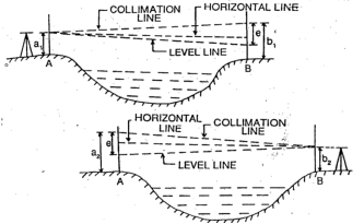
Let,
h= true difference of level between A and B
e= combine error due to curvature, refraction and collimation
(Error is +ve and –ve, here error is assumed +ve)
First case:
Correct staff reading A=a1
Correct staff reading B=b1 – e
True difference of level between A and B
h= a1 – (b1-e) ……………………………………………………..eq.1
Second case:
Correct staff reading B=b2
Correct staff reading a=a2 – e
True difference of level between A and B
h= (a2 - e) – b2 ……………………………………………………..eq.2
From (1) and (2)
2h= a1 – (b1-e) + (a2 - e) – b2
2h= a1 – b1 + e + a2 – e – b2
2h= (a1 – b1) + (a2 – b2)
h= [(a1 – b1) + (a2 – b2)] / 2
Key takeaways:
When it isn't always viable to find the leveling tool in among the inter seen factors, reciprocal leveling is performed. This case seems in case of ponds or rivers etc
The transient adjustment of a dumpy degree is composed of (1) Setting , (2) Leveling and (3) Focusing . During Setting, the tripod stand is installation at a handy top having its head horizontal (via eye estimation).
In a nicely adjusted dumpy level, preferred members of the family amongst essential strains are 1. Axis of the extent tube is perpendicular to the Vertical axis 2. Horizontal pass hair have to lie in a aircraft perpendicular to the Vertical axis, in order that it will lie in a Horizontal aircraft while the device is nicely leveled. 3. The Line of sight is parallel to the axis of the extent tube. 4. The optical axis, the axis of the goal lens and the road of sight have to coincide.
The modifications to be made at each putting of the device are referred to as temporary modifications. The following 3 modifications are required for the device on every occasion set over a brand new factor earlier than taking a reading: (i) Setting (ii) Levelling and (iii) Focusing. Setting Tripod stand is about at the floor firmly in order that its pinnacle is at a handy height. Then the extent is constant on its pinnacle. By turning tripod legs radially or circumferentially, the device is about leveled. Some gadgets are furnished with a much less touchy round bubble on tribrach for this purpose. Levelling Leveling of the device is completed to make the vertical axis of the device clearly vertical The system of correct levelling with 3 levelling screw is as given below: i. Loosen the clamp and flip the telescope till the bubble axis is parallel to the road joining any screws. Ii. Turn the 2 screws inward or outward similarly and concurrently until bubble is centered. Iii. Turn the telescope via way of means of 90° in order that it lies over the 1/3 screw and degree the device via way of means of running the 1/3 screw.
Turn again the telescope to its original function and test the bubble. Repeat steps (ii) to (iv) until bubble is focused for each positions of the telescope. v. Rotate the tool via way of means of 180°. Check the levelling. Focussing Focussing is essential to put off parallax at the same time as taking studying at the personnel. The following steps are required in focusing: Focusing the eyepiece: For this, preserve a sheet of white paper in the front of telescope and rotate eyepiece in or out until the move hairs are visible sharp and distinct. Focusing the objective:For this telescope is directed in the direction of the personnel and the focusing screw is became until the studying seems clean and sharp.
The everlasting modifications of various stage are made to set up the constant relationships among its essential lines. It suggests the rectification of instrumental errors In a dumpy stage, there are most effective modifications because the telescope is rigidly constant to the spindle. 1. The axis of the bubble tube ought to be perpendicular to the vertical axis 2. The line of collimation ought to be parallel to the axis of the bubble tube.
First Adjustment: To make the axis of the bubble tube perpendicular to the vertical axis. Object: The item of this adjustment is to make certain that if the tool is as soon as leveled up, the bubble stays within side the centre of its run for all positions of the telescope. Necessity: The adjustment is made most effective for the benefit of taking readings quickly. Since it's miles necessary that the bubble must be valuable whilst taking any reading, an awful lot time is wasted if this adjustment isn't made as if so the bubble needs to be added in centre whenever for every pointing of telescope.
Test: (i) Set-up the extent on corporation floor and degree it cautiously through tripod-legs and foot-screws. The bubble will now be valuable in positions at proper angles to every other, one being parallel to a pair of foot-screw and the alternative over the 0.33 foot-screw. (ii) Bring the telescope over a couple of foot-screws or over the 0.33 foot-screw and flip it thru a hundred and eighty within side the horizontal plane. If the bubble nevertheless stays valuable, the adjustment is correct. Permanent Adjustments of A Level 16 Adjustment: (i) If the bubble does now no longer stay within side the centre, notice down the deviations of the bubble from the centre, say it's miles ‘2n’ department over the bubble 1/2 of manner returned i.e., ‘n’ divisions through elevating or decreasing stop of the bubble tube by using capstan headed need to and the ultimate 1/2 of with the pair of foot-screws below the telescope at its present position. (ii) Turn the telescope thru 90° in order that it lies over the unmarried foot- screw under the telescope or parallel to a couple of this screw or pair of foot -screws and convey the bubble within side the centre of its run by using this screw pair of foot-screws. (iii) Rotate the telescope and spot if the bubble stays valuable for all positions of the telescope. If now no longer repeat the entire manner till the adjustment is correct.
Second Adjustment: To make the Line of collimation parallel to the axis of the bubble tube Object: The item of this adjustment is to set the road of collimation parallel to the bubble axis so that once the bubble is centered, the road of collimation need to grow to be precisely horizontal and now no longer continue to be willing as in any other case it might be. Necessity: The complete characteristic of a degree is to supply a horizontal line of collimation, that's possible simplest if the above circumstance is satisfied. Test and Adjustments: The collimation mistakes can be examined with the aid of using any of the subsequent 3 techniques after which the important changes are made (deal with Two-Peg Method) .
Key takeaways:
The transient adjustment of a dumpy degree is composed of (1) Setting, (2) Leveling and (3) Focusing. During Setting, the tripod stand is installation at a handy top having its head horizontal (via eye estimation).
There are two Methods of Levelling:
1. Height of collimation method
2. Rise and fall method
1. Height of Collimation method:
- In this method, the reduced level of collimation plane or height of instrument is determined for each set up of dumpy level and then reduced levels (R.L.) of the other points are found out with respect to the plane of collimation or height of instrument.
Level page of the field book
Staff Station | B. S | I.S | F. S | H.I (Collimation plane level) | R. L | Remarks |
B.M |
|
|
|
|
|
|
1 |
|
|
|
|
|
|
2 |
|
|
|
|
|
|
3 |
|
|
|
|
|
|
Procedure:
- Step 1: To prepare the format of level page before levelling work start:
For entering the readings of reduced level of different sights, the following format of level page is commonly used into practice.
- Step 2: To find the height of instrument (H.I.) or R.L. Of plane of collimation:
Keep the levelling staff on bench mark (B.M.) and take reading and find the reduced level of collimation plane or height of instrument by adding back sight reading to the R.L. Of bench mark.
Note that, Height of instrument is equal to R.L. Of collimation plane.
Height of instrument (H.I.) = R.L. Of bench mark + B.S. Reading.
- Step 3: To find R.L. Of intermediate points or change points:
Reduced level of intermediate points can be found out as follows:
R.L. Of intermediate points =Height of instrument - Intermediate sight reading
=H. I-. I.S. Reading
R.L. Of change point =Height of instrument - Fore sight reading
= H.I. - F.S. Reading
Note: When levelling work is to be stopped or change point is to be taken, then foresight reading is taken.
- Step 4: To find new height of instrument or new plane of collimation:
The instrument is shifted and set up and levelled at new position so that reading on levelling staff would be clear and distinct. Then take back sight reading on change point (C.P.) and find the R.L. Of new collimation plane or new height of instrument. Refer to Fig.
R.L. Of new height of instrument =R.L. Of change point + B.S.
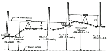
Fig: H.I Reading method
- Step 5: To find reduced levels of the remaining points:
Find the reduced levels of the remaining points from new set up of instrument with respect to new height of instrument or new R.L. Of collimation plane.
- Step 6: To finish the levelling work:
Repeat the above procedure till all the levelling work is over.
- Step 7: To find arithmetical check:
After completion of levelling work, arithmetical check is found out. From this check. Accuracy of the field work of levelling can be cross-checked. This check can be taken at each level page.
- Arithmetical check:
Sum of backsights - sum of foresights =Last R.L. - First R.L.
In short,  . -
. -  .= Last R.L. - First R.L.
- Note: It is noted that the arithmetical check can be taken at each level page.
The Rise and Fall method:
- In this method, instead of H.I. Column in the format of level page, two columns of rise and fall are introduced for calculation of R.L's. Difference of levels between consecutive points is found by comparing the staff readings on the two points for the same setting the instrument.
Rise and fall method is stepwise explained as follows:
- Step 1: Prepare the format of level page before levelling work start, as shown below:
Level Page of field book
Staff Station | B. S | I.S | F. S | Rise | Fall | R. L | Remark |
B.M |
|
|
|
|
|
|
|
A |
|
|
|
|
|
|
|
B |
|
|
|
|
|
|
|
C |
|
|
|
|
|
|
|
. |
|
|
|
|
|
|
|
. |
|
|
|
|
|
|
|
- Step 2: The difference in staff readings between the consecutive points is found out.
- Step 3:
- If the staff reading of second point in level page is higher than the first, then it indicates fall which is then to be subtracted from R.L.of previous point.
- If the staff reading of second point in level page is lower than the first one, then it indicates rise which is further to be added to the R.L. Of previous point.
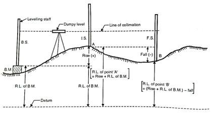
Fig: Rise and fall method
- Step 4: Repeat the same procedure till the levelling work is over.
- Step 5: After completion of levelling work, the arithmetical check is found out, which shows accuracy and cross check of the field work in levelling. Note that, the check can be taken at each level page and on R.L., of every intermediate points.
- Arithmetical check:
Sum of backsights - sum of foresights = Sum of all rise- sum of all= Last R.L. - First R.L.
In short, Σ B.S. -  . = Rise-fall=Last R.L – First R.L
- Note: It is noted that arithmetical check can be taken on R.L. Of intermediate points.
- In this method calculation work is more, therefore it is tedious but there is check on every point; hence it is accurate method rather than H.I. Method.
Key takeaways:
In this method calculation work is more, therefore it is tedious but there is check on every point; hence it is accurate method rather than H.I. Method.
Height of Instrument method:
Staff Station | B. S | I.S | F. S | H.I (Collimation plane level) | R. L | Remarks |
B.M |
|
|
|
|
|
|
1 |
|
|
|
|
|
|
2 |
|
|
|
|
|
|
3 |
|
|
|
|
|
|
Arithmetic Check:
ΣBS –ΣFS = LRL-FRL
Rise and Fall Method:
Staff Station | B. S | I.S | F. S | Rise | Fall | R. L | Remark |
B.M |
|
|
|
|
|
|
|
A |
|
|
|
|
|
|
|
B |
|
|
|
|
|
|
|
C |
|
|
|
|
|
|
|
. |
|
|
|
|
|
|
|
. |
|
|
|
|
|
|
|
Arithmetic Check:
ΣBS-ΣFS =LRL-FRL=
Missing records arise in survey studies due to the fact an detail within side the goal populace isn't always covered at the survey's sampling frame (non coverage), due to the fact a sampled detail does now no longer take part within side the survey (overall non response) and due to the fact a responding sampled detail fails to offer perfect responses to at least one or more
Missing facts arise in survey studies due to the fact an detail within side the goal populace isn't covered at the survey's sampling frame (non coverage), due to the fact a sampled detail does now no longer take part within side the survey (general non response) and due to the fact a responding sampled detail fails to offer desirable responses to 1 or greater of the survey items (object non response).
A type of techniques had been evolved to try to atone for lacking survey facts in a preferred reason manner that allows the survey's facts report to be analyzed without regard for the lacking facts. Weighting changes are frequently used to atone for non coverage and general non response. Imputation techniques that assign values for lacking responses are used to atone for object non responses. This paper describes the numerous weighting and imputation techniques which have been evolved, and discusses their advantages and limitations.
Key takeaways:
Missing records arise in survey studies due to the fact an detail within side the goal populace isn't always covered at the survey's sampling frame (non coverage), due to the fact a sampled detail does now no longer take part within side the survey (overall non response) and due to the fact a responding sampled detail fails to offer perfect responses to at least one or more
Curvature of the earth:
The earth appears to “fall away” with distance. The curved shape of the earth means that the level surface through the telescope will depart from the horizontal plane through the telescope as the line-of-sight proceeds to the horizon.
This effect makes actual level rod readings too large by:

Where D is the sight distance in thousands of feet
Effects of Curvature are:
- Rod reading is too high
- Error increases exponentially with distance
Atmospheric Refraction:
Refraction is largely a function of atmospheric pressure and temperature gradients, which may cause:
The bending to be up or down by extremely variable amounts.
The atmosphere refracts the horizontal line of sight downward, making the level rod reading smaller. The typical effect of refraction is equal to about 14% of the effect of earth curvature.
Combined Effect of Curvature and Refraction in Survey
The combined effect of curvature and refraction is approximately

The formula for computing the combined effect of curvature and refraction is:
C + R = 0.021K2
Where C = correction for curvature
R = correction for refraction
K = sighting distance in thousands of feet
3. Other sources of errors in levelling and their correction:
Type of Error | Correction |
1. Incorrect setting-up of instrument. |
|
2. Movement of staff from position when changing level station. |
|
3. Staff not held vertically. |
|
4. Parallax: Instrument knocked or moved during backsight-foresight reading |
|
5. Ground heating causes chaotic refraction of light |
|
6. Tripod or rod settles between measurements e.g., Bubble off center |
|
If the level is placed exactly midway between two points and staff reading are taken to determine the difference of level then an error is automatically eliminated but here in the case of a river or valley, it is not possible to set up the level midway between two points on the opposite bank so, the method of reciprocal levelling is adopted.
In reciprocal levelling, the level is set up on both bank of the river or valley and two sets of staff reading is taken by holding the staff on both banks in this case it is found that error is completely eliminated and true difference of level is equal to the mean of the two apparent differences of level.
Procedure:
1. Suppose A and B are two points on an opposite bank of a river. The level is set up very near A and after proper temporary adjustment staff reading are taken at A and B. Suppose reading a1 and b1
2. Level is shifted and set up very near B and after proper adjustment, staff reading is taken as A and B. Suppose the reading are a2 and b2
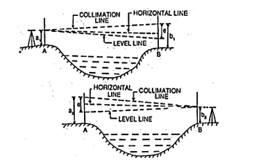
Let,
h= true difference of level between A and B
e= combine error due to curvature, refraction and collimation
(Error is +ve and –ve, here error is assumed +ve)
First case:
Correct staff reading A=a1
Correct staff reading B=b1 – e
True difference of level between A and B
h= a1 – (b1-e) ……………………………………………………..eq.1
Second case:
Correct staff reading B=b2
Correct staff reading a=a2 – e
True difference of level between A and B
h= (a2 - e) – b2 ……………………………………………………..eq.2
From (1) and (2)
2h= a1 – (b1-e) + (a2 - e) – b2
2h= a1 – b1 + e + a2 – e – b2
2h= (a1 – b1) + (a2 – b2)
h= [(a1 – b1) + (a2 – b2)] / 2
Levelling
Levelling may be defined as the art of determining the relative height or elevates of points or objects on the earth’s surface.
Instruments used for levelling:
Level
Levelling Staff
Level: The purpose of a level is to provide a horizontal line of sight.
Parts:
A telescope to provide line of sight
A level tube to make the line of sight horizontal
Levelling head to bring the bubble in its centre of run
A tripod to support the instrument
Dumpy level:
The telescope is fixed with the support and therefore, can neither be rotated about the longitudinal axis, or can it be removed from its support. A long bubble tube is attached at the top of the telescope. The levelling head generally consists of two parallel plates with either three-foot screw of four-foot screws. The upper plate is known as tribrach and the lower plate is known as trivet which can be screwed on a tripod.
Levelling staff:
- A levelling Staff is a straight rectangular rod having graduations, the foot of the staff representing zero reading.
- One is Folding type of 4m Levelling Staff:
- It consists of two wooden pieces each of 2m of length with the joint assembly. The thickness and width of staff are respectively 18m and 75mm. The folding joint is of the detachable type with locking device at the back.
- Hence the stand can be made into two parts for easy handling. When two pieces are locked together, the two pieces form a straight rigid levelling staff of length equal to 4m.
Distance of visible horizon
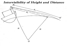
The maximum distance on ground that is visible to a person at certain height is called distance of visible horizon.
If there is no effect of refraction: -


 h=in meter, d=in km
Key takeaways:
Levelling may be defined as the art of determining the relative height or elevates of points or objects on the earth’s surface.
- Contouring in surveying is the dedication of elevation of numerous factors at the floor and solving those factors of equal horizontal positions within side the contour map.
- To exercising vertical, manage levelling paintings is accomplished and concurrently to exercising horizontal manage chain survey or compass survey or aircraft desk survey is to be accomplished.
- If the theodolite is used, each horizontal and vertical controls may be performed from the equal instrument.
- Based at the units used one could classify the contouring in unique groups.
Characteristic of Contour:
- The contour lines have the following characteristics
- All points on a contour line have the same elevation or R.L's. Fig. Shows the contour lines of equal elevation.
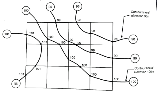
Fig: Contour lines of same elevation
- Two contour lines of different elevations cannot cross each other. However, in case of overhanging cliff two contour lines of different elevations can intersect. For such case, refer the Fig.
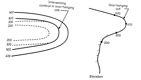
Fig: Intersecting contours in overhanging cliff
- Steeps slope:
(i)When contour lines come close together then it indicates steep slope. Fig. Shows steep slope along X-X.
(ii) Uniform slope: if contour lines are equally spaced, uniform slope is indicated.
(iii) A series of straight, parallel and equally spaced contours represent a plane surface.
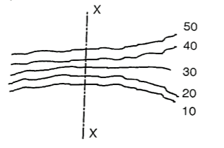
Fig: Steep slope along X-X
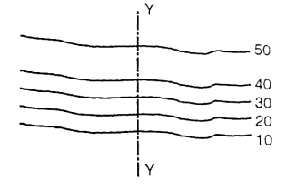
Fig: A gentle slope along Y-Y
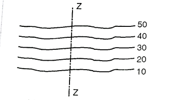
Fig: Uniform slope along Z-Z
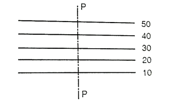
Fig: Plane surface slope along P-P
- Hill: Closed contour lines with higher values inside indicate hill. See Fig.
Depression: Closed contour lines with lower values inside indicate a depression.
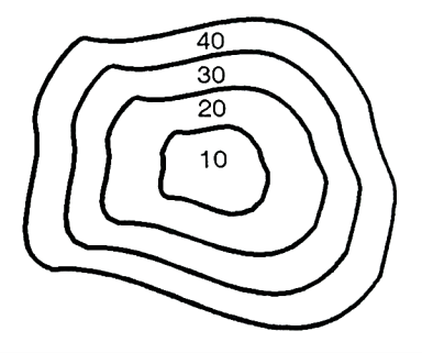
Fig: shows depression
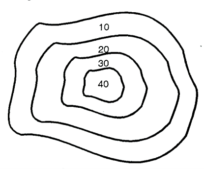
Fig: Shows a hill
Ridge line:
Fig. Indicates a ridge line. Contour lines cross ridge at right angles. For ridge line the higher elevation contour is inside the loop or band.
Valley line
Fig. Indicates a valley line. Contour lines also cross the valley lines at right angles. Valley line is indicated by higher elevation contours outside the loop.
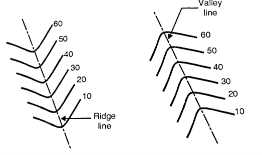
Fig: Ridge and valley line
Key takeaways:
- Contouring in surveying is the dedication of elevation of numerous factors at the floor and solving those factors of equal horizontal positions within side the contour map.
Methods of Contour Surveying
There are two methods of contour surveying:
- Direct method
- Indirect method
Direct method:
- In the direct method, the contour to be plotted is actually traced on the ground.
- These points are plotted on ground and contours are marked through them. This method is followed where great accuracy is required.
Procedure:
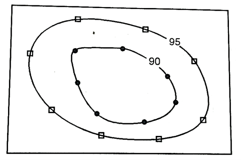
Fig: Direct method
- Consider an area as shown in Fig. Which is to be surveyed for contouring.
(a)The work is started from B.M. And level is setup at the centre of the area.
(b) Suppose it is required to find out the contour of 90.000 m then the staff should be moved to various positions on plot where the reading on staff should give R.L. Of 90.000 m. On ground. When all the points are located, they are marked on ground directly.
(c) Similar process is followed for locating the contour of 95.000 m and other contours.
Indirect method:
- In this method spot levels are taken at regular interval along predetermined lines on the ground. The work is then plotted on plan and then the required contour lines are drawn by the process of interpolation.
- The indirect method is less tedious and speedy as compared to direct method.
- The methods followed in indirect method of contouring are:
(a) By cross-section:
- This method is suitable for roads, railways and canal survey. Consider X, Y, Z as the centre line of the road or railway or canal route as shown in Fig. Cross sections are set at every 10 m on the centre line whereas the other dimension to complete a rectangle may be 5 m.
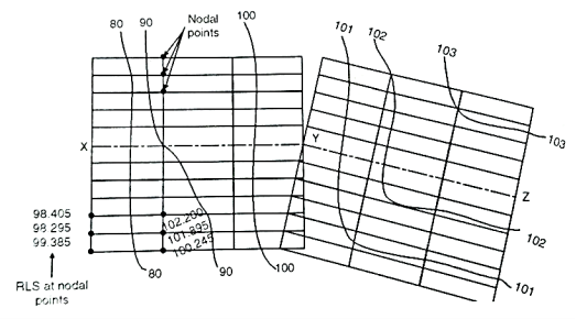
Fig: Method of cross-sections
- The spacing of the cross-section depends upon the nature of terrain. The cross-sections are more closely spaced where the contours curve abruptly. Staff readings of all the nodal points are determined and the R.L's are calculated. The same cross-section is plotted on the sheet to a suitable scale. The respective R.L's are written on the nodal point as shown in Fig. And then the required contours are interpolated between the R.L's.
(b) By squares:
- In this method the area to be surveyed is divided into a number of squares of size 5 to 20 m depending upon the nature of the ground and contour interval required. The elevations of the corners of the squares (called nodal points here) is determine by means of process of levelling. The calculated reduced level of these nodal points are then written on the respective nodal and contours are interpolated between them.
- This method is used when the area to be surveyed is small and the ground is not mush undulating because on undulating ground it would be practically impossible to form squares.
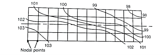
Fig: Method of square
(c) By tacheometric method:
- In the case of hilly areas, tacheometric contouring method is used. Here instrument known as tacheometer which is a theodolite, is utilized which determines horizontal distances and elevation of points.
- As shown in Fig. The tacheometer is set at a point approximately at the centre of the area. Radial lines are set making angles with either the magnetic meridian or with the first radial line. On each radial line staff readings are observed at different points. When the readings along all the radial lines have been observed, it is then plotted on a sheet to a suitable scale. The required contour lines are then interpolated as usual.
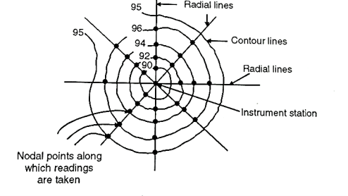
Fig: Tacheometric method
Uses of Contour maps:
The important uses of contour maps are:
Inter visibility between two points:
- A contour map can be used to determine the inter visibility of two points knowing the elevations of two stations at a farther distance. If a contour line passes in between them of more elevation then the stations will not be inter visible.
Calculation of reservoir capacity:
- The contour plan used to calculate the storage capacity of reservoirs. The areas between the contours are found by plan meter and multiplied by contours interval, will give the total volume of water that can be stored in a reservoir.
Drawing of sections:
- If a contours plan is given and a section is drawn along any direction, the general shape of the ground can be known.
- Fig. shows section of line PQ.
Location of Route:
- A contour plan is very much useful in locating the route of a highway, railway, canal or any other communication line Fig. Show route P to Q at an upward gradient.
Key Takeaways:
- Indivisibility between two points
- Calculation of reservoir capacity
- Drawing of sections
- Location of Route
References:
1. Duggal, S.K. Surveying Vol. I and II, Tata McGraw Hill, 2004.
2. Punmia, B.C. Surveying Vol. I and II, Standard Publishers, 1994.
3. Arora, K. R. Surveying Vol. I and II, Standard Book House, 1996
4 N.N Basak. Surveying and levelling