Unit - 5
Retaining Walls
- A Retaining wall is a shape that holds or keeps soil at the back of it. There are many styles of substances that may be used to create keeping partitions like concrete blocks, poured concrete, handled timbers, rocks or boulders.
- Some are smooth to use, others have a shorter existence span, however all can maintain soil.
- Gravity keeping partitions are partitions that rely upon their personal weight and setback to maintain the soil and are usually shorter in height.
- Allan Block keeping partitions are perfect for this form of wall, due to the fact as they're stacked collectively they lock into region to shape a setback. This setback enables the wall help the strain from the soils at the back of it.
- Reinforced keeping partitions are partitions that use a few form of reinforcement to offer extra energy to the keeping wall shape, as a consequence enhancing its cappotential to maintain the soils at the back of it. For SRW’s (Segmental Retaining Walls), we confer with this reinforcement as geogrid or grid. Geogrid is located among guides of blocks withinside the wall and rolled again into the slope or hillside throughout set up to create a more potent and extra solid soil mass.
- In layman’s terms, the blocks, the geogrid and the bolstered soil mass paintings collectively to make one large, heavy keeping wall shape. Sometimes grid isn't a usable answer on a assignment because of area or different web website online conditions, so opportunity reinforcement substances want to be used – along with no-fines concrete, soil nails or earth anchors. These styles of reinforcement usually require a neighborhood engineer for the layout and a licensed contractor for the set up
- There are different types of earth pressures in the lateral direction according to the structure against which the soil is retained and according to the equilibrium conditions.
- These are: Earth pressure at rest, active earth pressure, passive earth pressure.
- Earth pressure at rest is the earth pressure when the soil mass is not subjected to any lateral movement.
Lateral earth pressure:
- Soil in contact with any vertical or inclined face of structure exert force on structure which is known as lateral earth pressure.
Active earth pressure:
- It is pressure exerted on retaining wall resulting from slight movement of wall away from filling.
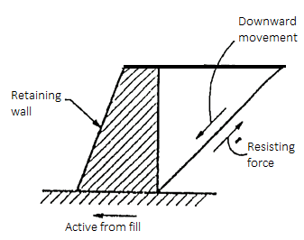
Fig 1.: Active earth pressure
Passive earth pressure:
- When the movement of the retaining wall is such that the soil tends to horizontally.
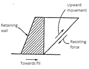
Fig 2: Passive earth pressure
Back fill:
- The material retained by retaining wall or supported structure is called back fill.
Surcharge
- The back fill may have its top surface horizontal or inclined. This back fill lying above horizontal place at elevation at top of wall is called as surcharge.
Assumptions made by Rankine for Earth Pressure:
Assumptions of the Rankine theory for active earth pressure are as follows:
- The soil mass is semi infinite, homogeneous dry and cohesionless.
- The ground surface is plane which may be horizontal or inclined.
- The back of wall is vertical smooth.
- The wall yields about the base thus satisfies deformation condition for plastic equilibrium.
- The soil element is in state of plastic equilibrium i.e. on verge of failure.
Key Takeaways:
There are different types of earth pressures in the lateral direction according to the structure against which the soil is retained and according to the equilibrium conditions. These are: Earth pressure at rest, active earth pressure, passive earth pressure.
Rigid Retaining Walls:
- Retaining partitions are enormously inflexible partitions used for helping soil laterally in order that it may be retained at extraordinary stages on the 2 sides.
- Retaining partitions are systems designed to restrain soil to a slope that it'd now no longer clearly preserve to (normally a steep, near-vertical or vertical slope).
- They are used to sure soils among extraordinary elevations regularly in regions of terrain owning unwanted slopes or in regions in which the panorama wishes to be fashioned significantly and engineered for greater precise functions like hillside farming or roadway overpasses.
- A maintaining wall that keeps soil at the bottom and water at the frontside is known as a seawall or a bulkhead.
Flexible Retaining Walls:
- Flexible keeping wall is a brand new kind of keeping shape built with the aid of using stacking 3-dimensional community geocells full of soil or gravel.
- The writers analyzed the interplay amongst wall, bolstered layers, and fill the usage of the finite detail software, MARC, and evaluated the pressure distribution of the geocell bendy keeping wall. Field trying out became performed to degree the lateral earth stress of a geocell bendy keeping wall built on an throughway in significant north China's Shanxi Province.
- It became proven that the deformation of bendy keeping wall became appreciably stimulated with the aid of using the width of wall, distance among adjoining bolstered layers, and basis modulus.
- The width of wall affected the pressure degree noticeably. The horizontal displacement of bolstered layers multiplied because the outside load implemented at the fill at the back of the wall multiplied.
- The horizontal pressure of tied bolstered layers advanced in 3 phases: bending, stretching–bending, and stretching because the outside load multiplied. Economic evaluation confirmed that the fee of geocell bendy keeping wall may be decreased with the aid of using 24%, which brings approximately superb financial benefits.
- Rankine's theory of earth pressure consider the theory of plasticity approach to find the stresses in the soil mass. The Rankine's theory is only applicable to smooth vertical wall. There are various ideal conditions used in practice of retaining wall problems.
- Coulomb's wedge theory can be applied to determine the active earth pressure for a backfill possessing both cohesion and effect of friction between the backfill and wall.
- Coulomb's theory consider a dry non-cohesive or dry cohesionless inclined backfill in which the lateral earth pressure required to balance the equilibrium of a sliding wedge with a slip surface can be determined.
Basic Assumptions of Coulomb's Wedge Theory:
Following are the various basic assumptions of coulomb's wedge theory
- The backfill is dry, non-cohesive (ie. Cohesionless), homogeneous, isotropic, soil (i.e. equal elastic properties in all direction). The backfill is elastically undeformable but breakable
- Backfill possessing both cohesion and internal friction or slip surface
- The failure surface or slip surface is a plane surface which passes through the heel of wall
- Failure is two dimensional. The backfill surface is plane and can be inclined.
- The position and the line of action of the earth pressure or direction of resultant earth pressure are known. The back of the wall can be inclined to the vertical
- The sliding wedge is itself considered as rigid body and the earth pressure is obtained by considering the limiting equilibrium of the sliding wedge as a whole.
Shape of the fallure surface:
- The shape of the failure surface which makes one of the boundaries of the sliding wedge is actually curved near the bottom of the wall in both active and passive cases due to wall friction. Hence there is curvature in slip surface due to friction itself.
Active earth pressure (Pa) for C= 0 backfill:
- In case of cohesionless backfill (i.e. non-cohesive backfill, C= 0), there are three forces kept the wedge under equilibrium. These three force are:
- Weight of wedge (W)
- Soil reaction force (R) on the failure plane and
- Earth pressure reaction (P)
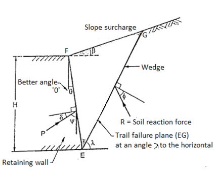
Fig 3: Wedge under the action of three forces,W,R and P
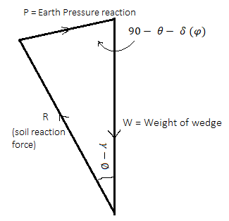
Fig 4: Force triangle W,R and P
- Fig. Shows the force triangle drawn from the known value of W and direction of all the three forces and magnitude of P is determined for the assumed trial wedge.
- There is maximum wall reaction for critical stip, plane and the wall should resist the maximum lateral pressure before it moves outward. Hence the maximum value of P is the active earth pressure.
- Note that in case of passive earth pressure, the wall should exert the smallest force so as to move the wedge for critical slip surface.
- In general; one of the drawback in coulomb's theory that it does not satisfy the static equilibrium condition. When the sliding surface is assumed to be plane, then three forces i.e. weight of wedge (W), soil reaction (R) and the earth pressure (P) acting on the sliding wedge do not meet at a common point. However based on the other assumption, the coluomb's theory is most effective in practice.
Active earth pressure for C-  backfill:
- Coulomb's theory can be used to find out the active carth pressure (P) for a backfill possessing both cohesion and friction.
- Following are the various forces acting on the wedge of soil at failure for C- backfill
- Weight of soil wedge (W)
- Earth pressure reaction (P) acting at an angle below the normal
- Soil reaction (R) on the failure plane acting an angle below the normal
- Force of adhesion (C2) between soil and wall
- Cohesive force (C) on the failure plane
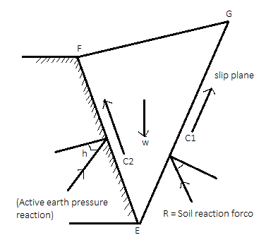
Fig 5: Forces acting on soil wedges at failure
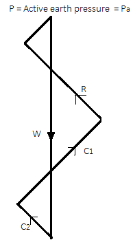
Fig 6: Polygon of forces
The force polygon as shown in Fig. Is drawn from the known values of W. C, C, and direction of all five forces and the value of p i.e. active earth pressure can be determined by closing side of a polygon.
Here C1=Cu x length of the slip plane EG
C2= unit adhesion (Cw) x length of wall in contact with the soil EF
Key Takeaways:
Rankine's theory of earth pressure consider the theory of plasticity approach to find the stresses in the soil mass. The Rankine's theory is only applicable to smooth vertical wall. There are various ideal conditions used in practice of retaining wall problems. Coulomb's wedge theory can be applied to determine the active earth pressure for a backfill possessing both cohesion and effect of friction between the backfill and wall.
Rankine’s State of Plastic Equilibrium in soils:
- Plastic equilibrium of soil: When every point of the soil body is on the verge of failure, then a body of soil is said to be in plastic equilibrium. In another word; every point of soil mass at rest condition is brought on the verge of failure by applying tension or compression, then the state so occurred is termed as a general state of plastic equilibrium.
- Rankine's was the only engineer who developed the concepts of plastic equilibrium to solve the stability problems.
- When plastic equilibrium conditions are realised in limited zones of soil, then it is termed as the local state of plastic equilibrium. The development of earth pressure on the retaining wall is part of backfill comes under the plastic equilibrium condition.
- Rankine considered a semi-infinite mass of soil comes under a horizontal surface and a vertical boundary as shown in Fig.
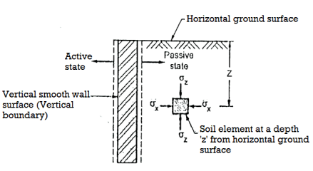
Fig 7: A semi-infinite mass of soil bound by a horizontal surface and a vertical boundary
- Rankine assumed the soil mass to be homogenous, cohesionless and dry
- Consider a soil element at a depth 'e' subjected to horizontal stress and vertical stress. There are no shear stresses acting on the horizontal and vertical planes, hence
 and
and  are the principal stresses.
 - When the soil mass as a whole is stressed in such way that the principal stresses of every point are in the same direction then it set up the network of failure plane. This network of failure plane is called as slip line field as shown in fig. Slip line field is equally inclined to the principal planes. When sufficient deformation of mass take place, only then plastic equilibrium is set up.
Key Takeaways:
Rankine's was the only engineer who developed the concepts of plastic equilibrium to solve the stability problems. When plastic equilibrium conditions are realised in limited zones of soil, then it is termed as the local state of plastic equilibrium
Active and Passive States due to wall movement:
When Wall Moves Away from Backfill:
- The value of horizontal stress decreases when away from backfill. If the expansion of soil element is more enough, then the value of horizontal stress (
 decreases to a minimum value and state of plastic equilibrium is set up called as active Rankine state as shown in Fig.
 - The Mohr's stress circle shows the state of elastic equilibrium as shown in Fig.
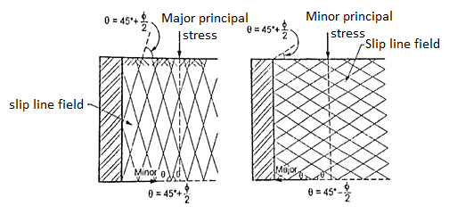
Fig 8: Active and passive Rankine state due to wall movement
Active Rankine state
- When the Mohr's stress circle touches the strength line drawn for the soil, then soil mass is active Rankine state.
- Note that plastic equilibrium state is developed due to decrease in the value of horizontal stress (
 ) it means it should be minor principal stress (
 ); vertical stress (
 ) and major principal stress (
 ), Minor principal stress due to decrease in the value of a, (horizontal stress) and Major principal stress.
When Wall Move towards the Backfill
- In such case, uniform compression is hold in the horizontal direction. There is an increase of horizontal stress (
 ) from its original value, but vertical stress (
 ) remains constant.
 - The diameter of stress circle becomes smaller due to increase of deformation and then reduces to zero. When the horizontal stress becomes more than vertical stress i.e.
 ,then diameter of stress circle increases until a state of plastic equilibrium is reached. At this state, horizontal stress (
 ) is maximum and hence it is a major principal stress (
 ) but
) but  , (vertical stress) becomes minor principal stress
  .
.
Passive Rankine state
- When Mohr's stress circle drawn with
 , an
, an d touches the strength envelope, then it will be reached with the maximum value of
  This state of soil of reaching the maximum value of o, is called as passive Rankine state and pressure so developed is called as passive earth pressure (pp).
Key Takeaways:
There are two situations:
- When Wall Moves Away from Backfill
- When Wall Move towards the Backfill
Rankine’s theory: Earth pressure on retaining wall due to submerged backfill:
- Fig. Shows the retaining wall with backfill submerged by the natural water table saturated water. In such case, the lateral pressure is the sum of the two components.
These two components are as follows,
- Lateral pressure caused by submerged weight (
 ) of the soil, k, y, z and
 - Lateral pressure caused by water (
 )
)
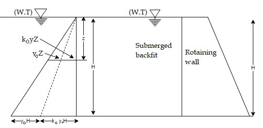
Fig 9: Submerged backfill
Here at any depth 2 below the horizontal surface active pressure is given by the following expression,
Pa=Ka sz+
sz+ z
z
Where, Pa=active pressure
 s= submerged weight of soil (y)
 unit weight of water
Fig. Shows the active earth pressure distribution diagram at any depth 'z' and at the depth H.
The active pressure at the base of wall, where z H is given by the following expression,
Pa=Ka sH+
sH+ H
H
Key Takeaways:
The active pressure at the base of wall, where z H is given by the following expression, Pa=KaγsH+γwH
Backfill with Uniform Surcharge:
- Fig. Shows the retaining wall with horizontal backfill which is loaded by a uniformly distributed surcharge of intensity "q" by assuming the vertical pressure at any, depth is increased by "q".
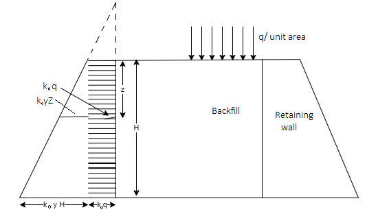
Fig 10: Retaining wall with backfill carrying uniform surcharge
∴Lateral active pressure at any depth 'z' is given by the following expression
Pa=Ka z+Kaq ….(at any depth z)
Where z =H, then, active pressure at the base is given
Pa=Ka H+Kaq .....(at height H from base of wall)
Backfill with sloping surface:
- Rankine's theory can also be applied for backfill with sloping surface at the constant angle
 to the horizontal.
 - To determine the active earth pressure in such case by Rankine's theory, an additional assumption are considered that the vertical stress and lateral pressure are conjugate stresses.
- The active earth pressure at a depth 'z' acting parallel to the slope is given by the following expression:
Pa= Ka γz , ...For sloping surface
Where, Ka=
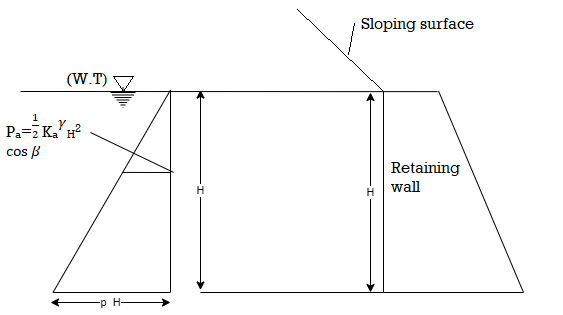
Fig 11: backfill with sloping surface
For horizontal ground surface;  =0
=0
Ka=
The total active pressure P, for a retaining wall having height 'II' is given by the following expression:
Pa= Ka
Ka H2
H2 
Layered backfill:
There are two cases for lateral pressure in layered soils which are as follows
- Same angle of shearing resistance
- Different angle of shearing resistance i.e.

(a) Lateral pressure for layered cohesionless soll
1. Same angle of shearing resistance with cohesionless soil layers
- In this case, if
 values for retained materials are considered to be same, then the pressure distribution diagram shows the same values of lateral pressure at same depth for same value of vertical stress (
 ) as shown in Fig.
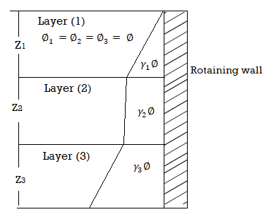
Fig 12: Layered soil with same angle of shearing resistance
(2) Different angle of sheering resistance with cohesionless soil layer
- When the upper and lower layers with different values of
 are considered, then the lateral pressure have a lower value for higher angle of friction and higher value of lateral pressure for a smaller angle of friction.
Fig. Shows layered soil with different angle of shearing resistance.
Let consider for the two layers as shown in Fig.
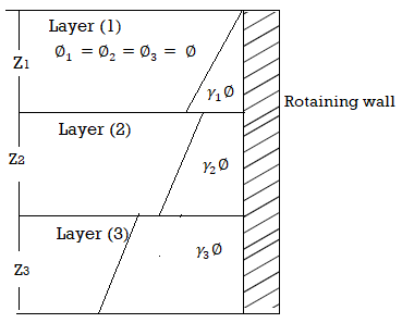
Fig 13: Layered soil with different angle of shearing resistance
For these two layers, ka1 > ka2, the active pressure are as follows:

Key Takeaways:
There are two cases for lateral pressure in layered soils which are as follows
- Same angle of shearing resistance
- Different angle of shearing resistance i.e.

- Despite the doubtlessly sizeable have an effect on of hysteria cracks on this planet pressures, nearly all of the prevailing techniques both do now no longer account for cracks or deal with them in a simplistic way while managing unsaturated soils.
- The principal goal of this have a look at is to quantify the have an effect on of hysteria crack formation on energetic earth pressures (AEP) in unsaturated backfills. A restriction equilibrium-primarily based totally framework for the dedication of the anxiety crack intensity (TCD) and AEP in unsaturated backfills is proposed.
- An powerful pressure method is hired along side logarithmic spiral failure geometry to evaluate the have an effect on of the interdependence among everyday pressure distributions, suction pressure, and soil tensile power at the formation of hysteria cracks beneathneath consistent go with the drift conditions. The most TCD is explicitly decided with the aid of using comparing a everyday pressure distribution and related tensile stresses mobilized alongside the crucial failure floor in retained backfill, without or with tensile power.
- A parametric have a look at is achieved on a hypothetical marginal backfill to analyze the effect of a anxiety crack on AEP with and with out thinking about the soil tensile power beneathneath exceptional go with the drift rates.
- The consequences imply that the formation of hysteria cracks will drastically boom AEP, at the same time as thinking about a nonzero tensile power as a feature of the matric suction will lower the TCD and AEP.
- Upon comparison, it's miles proven that conventional earth strain theories might also additionally drastically underestimate or overestimate TCD in unsaturated backfills.
- The proposed method provides a beneficial device for forensic research of failed systems and figuring out the intensity of cracks in current preserving earth systems which can be to be rehabilitated.
- Exploration, in general, should be carried out to a depth upto which the increase in pressure due to structural loading is likely to cause perceptible settlement or shear failure.
- Such a depth, known as the significant depth, depends upon the type of structure, its weight, size, shape and disposition of the loaded areas, and the soil profile and its properties.
- It is generally safe to assume the significant depth upto a level at which the net increase in vertical pressure becomes less than 10% of the initial overburden pressure.
- Alternatively, a pressure bulb bounded by an isobar of one-fifth or one-tenth of the surface loading intensity is sometimes assumed to define the minimum depth of exploration.
- This depth may be assumed to be equal to one-and a half to two times the width (smaller lateral dimension) of the loaded area.
Graphical methods:
Graphical methods are as follows:
Rebhan’s Graphical solution:
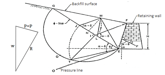
Fig 14: Graphical method by poncelet construction based on Rebhann’s principles
- In 1871, Rebhann's represented a graphical method to determine the total active pressure (Pa) based on Coulomb's theory on a rough wall with a cohesionless, homogenous and inclined backfill as shown in Fig.
- Fig. Shows poncelet construction for non-cohesive soils or cohesionless soils (C = 0) based on the principles made by Rebhann.
Procedure of graphical method:
Following is the procedure of construction to find out the active earth pressure by graphical method refer Fig.
- Draw a retaining wall to a suitable scale and measure the backfill surface angle for required position as shown in Fig.
- Draw a -line EG such that it intersect the backfill surface at G.
- Draw a semi-circle BQG by taking diameter as EG.
- Draw the pressure line 'EO' at an angle of (a-5) with respect to o-line.
- Draw FI parallel to pressure line 'EO'.
- Draw a perpendicular to EG at I such that it cut the semi-circle at T.
- With centre E and radius ET, draw an are such that it cut EG at J.
- Draw JM parallel to FI
- Now EM is a rupture line
- Taking as a centre and IM as the radius draw at a such thar EG at L
After this construction from step 1 to 10, it shows the  LIM. Area of
  LIM in its natural unirs multiplied by the unit weight of the soil (
 ) gives the active earth pressure (Pa) as follows:
Pa=Area of triangle LJM= *JM*MN
Where,  =unit wt of the soil
JM length of a triangle LJM
MN=height of  LJM
LJM
Pa=Active earth pressure
Key Takeaways:
In 1871, Rebhann's represented a graphical method to determine the total active pressure (Pa) based on Coulomb's theory on a rough wall with a cohesionless, homogenous and inclined backfill.
Culmann’s Graphical solution:
- Culmann's graphical method is rather general method than Rebhann's method. This method is same as the trial wedge method. The force triangle or force polygon can directly be constructed on o-line EG considering EG as a load line.
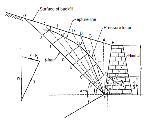
Fig 15: Culmann’s graphical method for determining active earth pressure
- This method can be used to evaluate the coulomb's earth pressure fr ground sa face of any configuration, different types of surcharges and layered backfills.
- Fig. Shows the Culmann's graphical method of determine active earth pressure (P) for non-cohesive soils or cohessionless soils (i.e. C= 0)
Graphical construction procedure;
- Various steps involved in the procedure are as follows:
- EF it a retaining wall as shown in Fig. 5 in 1(a) drawn to a suitable scale.
- Draw -line EG at an angle with respect to horizontal.
- Mark on EG, the distances EA, EC, ED, EL, EJ etc to a suitable scale representing the weight of wedges EFA, EFC, EFD, EFI, EFI etc respectively.
- Draw lines parallel to pressure line ET from the points A, C, D, I J such that it intersects assumed rupture line EA, EC, ED, EI, EJ at points A,C,D,1,J respectively.
- Then point A', C, D, I', J' are joined by a smooth curve representing the pressure locus.
- Select point B' on the pressure locus in such way that the tangent to the curve at this point parallel to line EG
- Draw B'B parallel to the pressure line ET. The magnitude of B'B" itself in its natural units gives the active earth pressure (Pa)
- Points E and B' are joined and extended further so as to meet the surface of backfill at B Then EB is the rupture line.
- Note that, for the plane backfill surface, the point of application of active earth pressure (Pa) is at a height 1/3 of from the base of retaining wall.
Key Takeaways:
Culmann's graphical method is rather general method than Rebhann's method. This method is same as the trial wedge method.
Numericals:
Q. Compute the active earth pressure at a depth of 4.5m in a sand whose angle of friction is 37 degree and density of 15.60KN/m3 in dry state.
Given: H = 4.5m,  = 37% ,
To compute the active earth pressure at a depth H in dry state
We know,
From Rankine's theory, active earth pressure (p) at a depth His given by:
Pa=Ka ….(1)
….(1)
Where Ka=coefficient of active earth pressure=
∴Ka= =0.248
Substituting Ka=0.248 in equation 1 we get,
Pa=0.248×15.60×4.5
∴Pa=17.4kN/m3
Q. A smooth vertical wall retains a level surface with  to a depth of 8m. Compute the total active pressure in dry condition and when water table rises to the GL Assume
Given :H=depth=8m


To compute the total active pressure Pa in dry condition:
Ka=Coefficient of active earth pressure=
∴Total active earth pressure in dry condition (Pa)
=Ka =1/3×18×8
Pa=48KN/m3
To compute the total active earth pressure when water table rises to the GL(i.e submerged soil)

∴Total active earth pressure(Pa)
=
∴Pa=112KN/m2
References:
- Soil Mechanics and Foundation Engineering by Dr.B.C.Punmia, Laxmi Publication
- Geotechnical Engineering by T.N.Ranamurthy & T G Sitharam, S Chand Publications.
- Principles of Geotechnical Engineering by Braj M.Das, Cengage Learning.
- Geotechnical Engineering by P.Purushothma Raj, Tata Mc Grawhill.