Unit - 6
Sub-surface Exploration
- The basic aim of sub-surface exploration or site investigation is to obtain the information about the surface conditions at the site of proposed construction.
- For every big or major engineering project site investigations are essential, since it is beneficial for the design of structures and for planning construction techniques.
Key Takeaways:
The aim of sub-surface exploration or site investigation is to obtain the information about the surface conditions at the site of proposed construction.
Necessity of subsoil exploration:
Site investigation for one or more of the following purposes is carried out
- Determination of the bearing capacity of the soil.
- Selection of type and depth of foundation for a given structure.
- Investigation of the safety of the existing structures and for necessary remedial measures.
- Selection of suitable construction technique.
- Calculation of the lateral earth pressure against retaining walls and abutments.
- Estimation of probable maximum and differential settlements.
- Prediction and solving of potential foundation problems.
- Establishing the ground water table level and determination of the properties of water.
- Determining the suitability of the soil as a construction material.
Planning for subsoil Exploration:
Soil exploration involves broadly the following:
- Planning of a programme for soil exploration.
- Collection of disturbed and undisturbed soil or rock samples from the holes drilled in the field. The number and depth of holes depend upon the project.
- Conducting all the necessary in-situ tests for obtaining the strength and compressibility characteristics of the soil or rock directly or indirectly.
- Study of ground-water conditions and collection of water samples for chemical analysis.
The ground investigation, irrespective of the magnitude of the project, consists of four phases:
- Available information
- Reconnaissance
- Preliminary investigation
- Detailed investigation
1. Available information:
- This is the first phase in which collection of published geological and topographical information of the area, hydrological data, details of existing or historic development, local regulations for construction activity etc. are made.
2. Reconnaissance:
- This is the phase during which first examination of the area is made by the engineer along with other specialists, such as the geologist, land surveyor, geotechnical engineer, etc.
- At this stage a thorough study of the existing structures for the type of construction and defects such as cracks and settlement, soil profiles in highway or railroad cuts and quarries, erosion in existing cuts, high water marks on bridge abutments, rock outcrops, history of flood and scour levels from the local people are collected.
3. Preliminary investigation:
- This is an important phase of the entire program. In this stage the engineer plans the investigation program. The first step towards a ground investigation is a thorough understanding of the geology of the site, which enables an efficient working out of the investigation program.
- The second step is to obtain more details of the subsoil strata (e.g. Thickness of individual strata) from one or two exploratory drill holes. All other further steps depend on the magnitude of the job and the character of the soil profile.
- During this stage the possible location of the ground water is also found. For small jobs this preliminary investigation itself may be sufficient. It is a common practice to limit the number of quality samples recovered except the one obtained from penetration tests.
- The strength and settlement are estimated from standard correlations using index properties and supplemented by the results from samples obtained from penetration tests. Further, this is the stage which practically decides the feasibility of the project.
4. Detailed investigation:
- Additional borings and deep borings are planned from the data obtained from the preliminary borings and deep borings. If the subsoil is uniform in stratification, an orderly spacing may be planned.
- Many a times additional borings are made to locate weak soil or rock zones, outcrops etc. which may influence the design and construction of the project. Drilling is required to bore a hole into hard strataor boulders. It can be done by percussion or rotary method of drilling.
- Necessary in-situ tests should also be performed. Sufficient samples should be procured to obtain relevant parameters for design and construction. Certain additional samples should be recorded to redefine the design or construction procedure.
Key Takeaways:
The ground investigation, irrespective of the magnitude of the project, consists of four phases:
- Available information
- Reconnaissance
- Preliminary investigation
- Detailed investigation
Preliminary investigation:
- This is an important phase of the entire program. In this stage the engineer plans the investigation program. The first step towards a ground investigation is a thorough understanding of the geology of the site, which enables an efficient working out of the investigation program.
- The second step is to obtain more details of the subsoil strata (e.g. Thickness of individual strata) from one or two exploratory drill holes. All other further steps depend on the magnitude of the job and the character of the soil profile.
- During this stage the possible location of the ground water is also found. For small jobs this preliminary investigation itself may be sufficient. It is a common practice to limit the number of quality samples recovered except the one obtained from penetration tests.
- The strength and settlement are estimated from standard correlations using index properties and supplemented by the results from samples obtained from penetration tests. Further, this is the stage which practically decides the feasibility of the project.
Detailed investigation:
- Additional borings and deep borings are planned from the data obtained from the preliminary borings and deep borings. If the subsoil is uniform in stratification, an orderly spacing may be planned.
- Many a times additional borings are made to locate weak soil or rock zones, outcrops etc. which may influence the design and construction of the project. Drilling is required to bore a hole into hard strataor boulders. It can be done by percussion or rotary method of drilling.
- Necessary in-situ tests should also be performed. Sufficient samples should be procured to obtain relevant parameters for design and construction. Certain additional samples should be recorded to redefine the design or construction procedure.
There are three types of soil samples:
1. Undisturbed Soil Samples:
- The soil pattern, wherein the particle length distribution in addition to the soil shape and the residences of the in situ stratum, stay preserved, is named as undisturbed soil samples. Such soil samples are required for shear energy and consolidation assessments.
- This soil samples may be accrued via way of means of preventing the dull system at a sure stage after which placing the proper sampler under the lowest of the bore.
2. Representative or Disturbed Soil Sample:
- The soil pattern which includes the identical particle length distribution as withinside the in situ stratum, however the herbal shape of pattern receives in part or completely disturbed and modified, is known as a consultant or disturbed soil pattern.
- Such disturbed soil samples may be used for
- Identification of soil types
- Determining Atterberg limits, precise gravity, natural and carbonate content.
- Compaction assessments etc.
3. Non-consultant Soil Sample:
- These are combinations of soil from one of a kind soil strata. These samples are received via way of means of auger dull or sedimentation of wash dull. Such samples may also assist in figuring out the intensity at which most important modifications in soil profile occur.
Key Takeaways:
There are three types of samples:
- Undisturbed soil sample
- Disturbed soil sample
- Non-consultant soil sample
Types of Soil Samplers:
Types of samplers are as follows:
- Open drive sampler
- Stationary piston sampler
- Split barrel or split spoon sampler
- Rotary sampler
- Disturbed and undisturbed sampling
- Block or chunk samples
Open Drive Sampler:
- Open drive sampler consists of a steel tube with screw thread at each end. Cutting shoe is attached to one end of the tube.
- The other end of tube screws into a sampler head to which in turn the boring rods are connected.
- The sampler head also incorporates a non-return valve to allow air and water to escape as the soil fills the tube and to help retain the sample as the tube is withdrawn.
- The open drive sampler can be driven or jacked. After. Withdrawal the cutting shoe and sampler head are detached and the ends of the sample are sealed and it is then send to laboratory.
- The sampler is suited for clayey soil. When used to obtain samples of sand a short length of tube with spring loaded flaps should be fitted between the tube and cutting shoe to prevent loss of soil. Due to cutting shoe provided at bottom area ratio is higher (30%) than thin walled sampler.
Stationary Piston Sampler:
- Here we have thin walled tube fitted with a piston. The piston is connected to a rod passing through sampler head and run inside hollow boring rod.
- Sampler is first lowered into the bore hole, piston being located at the lower end of tube. The tube and piston could be locked together by a clamping device which is provided at the top of rods. Piston thus prevents water or loose soil from entering the tube.
- Now the piston is held against the soil by clamping the piston rod to the casing and the tube is pushed past the piston until the sampler head meets the top of the piston to obtain a sample.
- The sampler is then withdrawn holding the piston at the top of tube as this takes place. The vacuum between piston and sample help to retain the soil in the tube. Piston samplers are always pushed by mechanical or hydraulic jacking and they are not driven. This sampler is generally used for soft clays.
Split barrel or Split Spoon Sampler:
- This sampler is used in standard penetration test tube which splits longitudinally into two halves is used here. There is a considerable disturbance in the sampler and useful in sandy type of soils. Outside and inside diameter of tube is 51 mm and 35 mm. Area ratio is 112%.
Rotary Sampler:
- Rotary sampler is a double-walled tube sampler with an inner removable liner. The outer tube is provided with a cutting bit. The bit cuts an annular ring when the barrel is rotated.
- The inner tube which is stationary, slides over the cylindrical sample cut by the outer rotating barrel. The quality of sample obtained with double walled tube sampler is better than that obtained with single tube sampler.
- Rotary samplers are useful for sampling in firm to hard cohesive soils and particularly in rocks. The rock quality can be estimated from the core recovery ratio termed as rock quality designation, RQD.
- The ratio of the total length of core recovered to the length of sampler advanced on a given run, expressed as percent, is the value of RQD. While determining the length of core recovered, only those piece of core which are atleast 100 mm long, hard and sound, are considered. Breaks caused by drilling should be ignored.
- The diameter of the core should preferably be not less than 54 mm. From RQD, it is also possible to assess the in situ (field) modulus of elasticity and compressive strength of the rock mass (q) based on the corresponding values (E, and q₁) obtained by laboratory tests on rock cores.
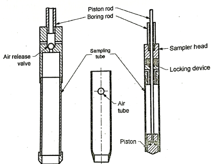
Fig 1: Open drive sampler, Thin tube sampler, Stationary Piston sampler
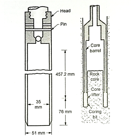
Fig 2: Split spoon sampler, Single tube core barrel
Disturbed and Undisturbed sampling:
- Testing of soil samples in the laboratory must reflect, as close as possible, the conditions of the soil mass in the field or else the prediction based on properties measured in the laboratory will be different from the performance observed in the field.
- Samples obtained more or less in the same conditions as in the field are acceptable as undisturbed samples for laboratory testing. For example, chunk sample. Engineering properties are determined on undisturbed samples.
- However, a soil sample obtained from the field, necessarily involves some disturbance during sampling, transport, extraction and handling.
- This disturbance may be in the form of change in water content, soil structure, stress condition, density or grain size distribution such sample are called disturbed samples which can be used for determination of properties like grain size, water content, specific gravity, density index, consistency limits.
Block or Chunk Samples:
- Block samples can be obtained from open excavations like test pits, shafts, etc. from soil which has a trace of cohesion.
- During excavation, a block of soil about 40 cm x 40 cm in plan, is left undisturbed. An undisturbed of about 30 cm x 30 cm x 30 cm or any convenient size is usually trimmed with a knife is then slided over the trimmed block.
- The space between the side of the box and the sat with dry sand. The end of the box is sealed with paraffin wax. These samples if transported to long distance may get disturbed during transit.
- They can be used for any laboratory tests by careful trimming. But these samples cannot be obtained below water level.
- Undisturbed samples may also be obtained by means of a sampling tube of 100 mm diameter with a sharp cutting edge.
- The soil surrounding the outside of the tube should be carefully removed while tube is being pushed in.
Key Takeaways:
Types of samplers are as follows:
- Open drive sampler
- Stationary piston sampler
- Split barrel or split spoon sampler
- Rotary sampler
- Disturbed and undisturbed sampling
- Block or chunk samples
Auguring:
- It is quite useful in cohesive and other soft soils above water table.
- Hand-operated auger methods suitable for are identifying various types of soils with depth and also for getting information about the depth to the ground water table for deeper boring, solid or hollow-stem, continuous-flight augers (rotary augers) are frequently used.
- As the drill advances, additional auger flights are added and soil is brought to the surface in a disturbed form.
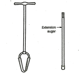
Fig 3: Types of Auger
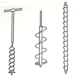
Fig 4: Types of Auger
- In auger boring it is possible to identify even disturbed soils. Since the borehole is kept dry, it is particularly suitable for advancing borings above water table to obtain undisturbed partially saturated samples. It further facilitates the determination of free water level.
- Augers can be operated mechanically or manually. Hand augers used for depths upto about 6 m and mechanically operated augers are used for greater depth and they can be used in gravely soils.
- The hand augers used in boring are about 15 to 20 cm in diameter. The lower end of hand auger is attached to a pipe of 18 mm diameter.
- For taking samples from readily driven hole, a auger known as 'Post-Hole Auger' is used.
- Mechanical augers are driven by power.If depth of bore hole increases above 12 m, then mechanical augers become inconvenient and other boring methods are used.
- Auger boring becomes trouble-some, when there are large boulders or cobbles are met. The site investigation is done quite rapidly and economically by using auger boring.
Key Takeaways:
It is quite useful in cohesive and other soft soils above water table.Hand-operated auger methods suitable for are identifying various types of soils with depth and also for getting information about the depth to the ground water table for deeper boring, solid or hollow-stem, continuous-flight augers (rotary augers) are frequently used.
Wash Boring:
- Wash boring is commonly used for the boring in difficult soil. To start with, the hole is advanced a short depth by auger and then a casing pipe is pushed to prevent the sides from caving in.
- The hole is then continued by the use of a chopping bit fixed at the end of a string of hollow drill rods.
- Stream of water under pressure is forced through the rod and the bit into the hole, which loosens the soil as the water flows up around the pipe.
- The loosened soil in suspension in water is discharged into a tub. The soil in suspension settles down in the tub and the clean water flows into a sump which is reused for circulation. The motive power for wash boring is either mechanical or man power.
- The soil sample obtained by this method is known as wash sample. It is used to describe soil profile approximately by change in colour of soil suspension. Approximate size gradation can also be determined by this sample.
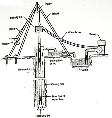
Fig 5: Wash Boring
- Mainly wash boring is used for drilling holes in the ground. Once hole is drilled, a sampler is inserted to obtain soil samples for laboratory testing.
Advantages:
- Instrument used is relatively light in weight.
- Inexpensive method
- Fast and simple method.
Disadvantages:
- It is slow in stiff and coarse grained soils.
- Cannot be used in rocky strata.
- Good quality undisturbed samples cannot be obtained.
- Not suitable in areas where ground water table is very near to ground.
Key Takeaways:
Wash boring is commonly used for the boring in difficult soil. To start with, the hole is advanced a short depth by auger and then a casing pipe is pushed to prevent the sides from caving in.
Rotary Drilling (Core Boring or Core Drilling):
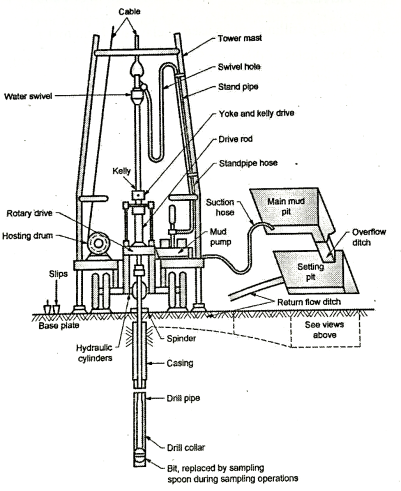
Fig 6: Rotary drilling rig
- Rotary boring or rotary drilling is a very fast method of advancing hole in the rocks and soils. In this method hole is drilled by rotating a hollow drill rod which has a cutting bit at its lower end. At the top of drill rod, drill head is provided.
- It comprises of a rotary mechanism and an arrangement for applying pressure.
- When the drilling rod is rotated, the cutting bit shears off chips of the material penetrated. A drilling fluid is introduced under pressure through the drilling rod to the bottom of the hole.
- The cuttings of the material penetrated are carried to the ground by the fluid through the annular space between the drilling rod and the walls of the hole. Another function of fluid is to cool the drilling bit. The drilling fluid also supports the walls of the hole, in case of un-cased hole.
- The drilling bit is replaced by a sampler, when soil sample is required to be taken.
- Drilling may be done by a diamond studded bit or a cutting edge having chilled shot. The diamond drilling is costlier, but is superior to the other type drilling. If double tube core barrel is used, it gives good quality of the rock sample.
Advantages:
- Rotary drilling can be used in clay, sand and rocks.
- Bore holes of diameter 50 mm to 200 mm can be easily drilled by this method.
Disadvantages:
- If soil is containing a large percentage of particles of gravel size and larger, this method is not well adapted. Because, the particles of this size start rotating below the drill rod and it becomes difficult to drill the hole.
Key Takeaways:
Rotary boring or rotary drilling is a very fast method of advancing hole in the rocks and soils. In this method hole is drilled by rotating a hollow drill rod which has a cutting bit at its lower end. At the top of drill rod, drill head is provided.
Percussion Drilling:
- Percussion drilling is another method of drilling hole in which a heavy drilling bit is alternately raised and dropped in such a manner that it powders the underlying materials and forms into slurry in water. This slurry is removed out of the hole by means of bailers or sand pumps.
- In all types of drilling the sides of the holes may be stabilized, if required, by the use of drilling mud or casing pipes. A drilling mud is nothing but bentonite clay mixed in water.
- The machinery used to advance holes and take sample is called a drill rig.
- Percussion drilling method is specially used for making holes in rocks, boulders and other hard strata.
- Percussion drilling consists of lifting and dropping of a very heavy chisel in a vertical hole. The material gets pulverized.
- Water is added to the hole, if the chisel strikes above water table. The water forms a slurry of a disintegrated material, which is removed by sand pump or a boiler at intervals.
- Casing may be required for this method. For drilling tube well also percussion drilling is used.
Advantages:
- Percussion drilling can be used in all types of soils.
- It is very much useful for boring holes like that for tube well through rock or boulders.
Disadvantages:
- Because of heavy blows of the chisel, the material at the bottom is in disturbed state.
- More expensive as compared to other methods.
- Difficult to detect minor changes in the properties of the strata penetrated.
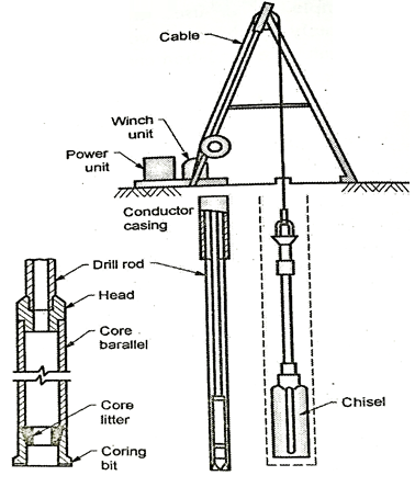
Fig 7: Rotary drilling and Percussion drilling resp.
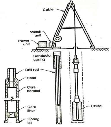
Fig 8: Wash boring arrangement and Bailer resp.
Key Takeaways:
Percussion drilling is another method of drilling hole in which a heavy drilling bit is alternately raised and dropped in such a manner that it powders the underlying materials and forms into slurry in water. This slurry is removed out of the hole by means of bailers or sand pumps.
Standard Penetration Test:
- The tests essentially consists in diving a split spoon sampler of 50 mm outside diameter into the soil
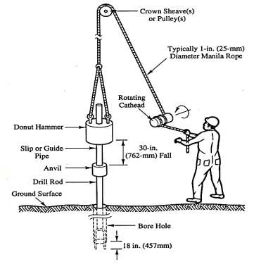
Fig: 9
- The sample should to be driven at rock bottom of borehole that is cased in a very pipe is forced into the bore hole and take a look at conducted at rock bottom of the bore hole.
- In case the strata is stiff like gravels and sandy mallet, a solid cone like 60° shoe is fitted to the sampler. The sampler is to be hooked up to the drill rods and driven by blows of a hammer. The hammer typically
- The sampler is to be hooked up to the drill rods and driven by blows of a hammer. The hammer typically weighs sixty five weight unit with a free fall of 750 mm. Typically thirty blows per minute are given.
- The sampler is at first driven a distance of one hundred fifty mm below very cheap of bore hole and so an additional distance of three hundred mm.
- The number of blows needed to drive this distance is thought as customary penetration price N.
- The number of blows needed to result the primary one hundred fifty mm of penetration, known as the seating drive, is forgotten
- The split-spoon sampler is then withdrawn and it detached from the drill rods. The split-barrel is disconnected from the cutting shoe and also the coupling. The soil sample collected within the split barrel is rigorously collected on preserve the natural wet content and transported to the laboratory for tests. Sometimes, a skinny liner is inserted inside the split-barrel in order that at the tip of the S P T, the liner containing the soil sample is scaled with liquefies wax at each its ends before it's got rid of to the laboratory
Then take a look at is halted If-
a) 50 blows area unit needed for any a hundred and fifty metric linear unit penetration
b) one hundred blows area unit needed for three hundred penetration.
c) 10 sequent blows turn out no advance and is termed as refusal.
The following precautions ought to be taken whereas closing the take a look at
a) The split spoon sampler should be in condition and the cutting shoe should be free from wear tear.
b) The drop press should be of the correct weight and the fall ought to be free, resistance.
c) Very cheap of the borehole should be properly clean before the take a look at is administrated. Otherwise the take a look at gets administrated within the loose, disturbed soil and not within the undisturbed soil.
d) Once a casing is employed in borehole, it ought to be ensured that the casing is driven simply wanting level at that the S P T is to be administrated. Otherwise, the take a look at gets administrated in a very soil of very cheap of the casing
- S P T is extensively used as a result of the take a look at is straightforward and economical. It is the sole take a look at that has representative soil samples each for visual scrutiny for natural wet content and classification tests within the laboratory.
- Design charts for shallow foundations resting on cohesion less soils are developed.
Limitations of SPT:
- As SPT is subject to several errors, S P T price isn't terribly reliable.
- 2 In granular soils, correlation between S P T and internal friction angle is incredibly poor.
- Determination of allowable bearing pressure from N values isn't correct.
- S P T price isn't acceptable for determinant the bearing pressure in fine-grained cohesive soils,
- Corrections for overburden and impact square measure to be applied to record N values for correlation with soil properties
Applications of SPT:
- SPT is appropriate for each cohesive and non-cohesive soil variety of SPT is extensively used as a result of the take a look at is easy and comparatively economical.
- It is the sole take a look at that gives representative soil samples each for visual scrutiny within the field and for natural wet content and therefore the classification tests within the laboratory
- This take a look at is employed to work out the density index of sandy soils and consistency of cohesive soils. Variety of tried and true correlations square measure out there between N price and soil parameters each for cohesive and non cohesive soils.
Key Takeaways:
SPT is appropriate for each cohesive and non-cohesive soil variety of SPT is extensively used as a result of the take a look at is easy and comparatively economical.
Cone Penetration test:
- In this test, a cone which has an apex angle of 60°and attached to drill rods is driven into soil with a hammer of 65 kg, falling freely from a height of 750 mm.
- The blow count for every 100 mm the cone is continuously recorded. The cone is driven till refusal or upto the required depth and drilling rods are withdrawn, leaving the cone behind in the ground.
- The number of blows required for 300 mm penetration is noted as the dynamic cone resistance. This test gives a continuous record of Ned with depth. No sample, however, can be obtained in this test.
- Dynamic cone penetration tests are performed either by using a 50 mm diameter cone with bentonite slurry (IS:4968-Part I-1976) or a 65 mm diameter cone with bentonite slurry (IS: 4968).
- When bentonite slurry is used, the set-up has an arrangement for the circulation of slurry so that drill rod is eliminated.
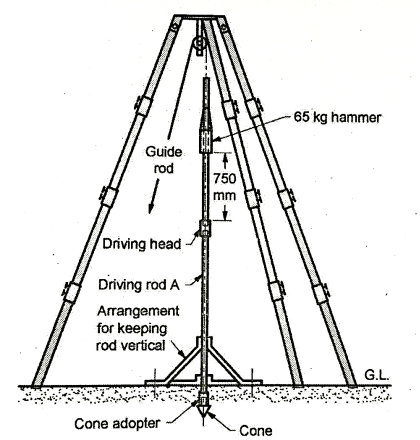
Fig 10: Typical Assembly of equipment for dynamic cone penetration test
- The dynamic cone test is a quick test and helps to cover a large area under investigation economically.
- It helps in identifying the uniformity or the variability of the subsoil profile and is found to be a less expensive and much quicker than the SPT.
- If the tests are carried out close to a few boreholes, the results obtained from DCPT can be compared with the SPT data and correlation between the two established for the particular site conditions.
- The correlation can then be used to obtain N values from Nand N, applicable for medium to fine sands are given below:
When a 50 mm diameter cone is used,
Ncd = 1.5 N for depths upto 3 m
Ncd =1.75 N for depths from 3 m to 6 m
Ncd = 2.0 N for depths greater than 6 m
- The Central Building Research Institute, Roorkee, has developed the following correlations between Ncbr and N when a 65 mm diameter cone is used without bentonite slurry.
Ncbr =1.5 N for depths upto 4 m
Ncbr =1.75 N for depths from 4 m to 9 m
Ncbr = 2.0 N for depths greater than 9 m
Key Takeaways:
In this test, a cone which has an apex angle of 60°and attached to drill rods is driven into soil with a hammer of 65 kg, falling freely from a height of 750 mm.
Static Cone Penetration test:
This test is used in place of SPT, particularly for soft clays and silts and fine to medium sand deposits.
The penetrometer used consists of a cone with an apex angle of 60° and a base area of 10 cm, and is used as is as follows-
- Initially the cone and the friction jacket assembly is in a stationary position.
- The cone is then pushed into the soil at the rate of 20 mm/s by the inner sounding rod at a steady rate till a collar engages the cone. The force Qc offered by soil for penetration is measured on pressure gauge, and tip resistance point resistance, qc can be calculated qc=Qc/Ac where Ac is the base area.
- The sounding rod is pushed further pushing the friction jacket and the cone assembly together. The total force Qt required for this is again read on the pressure gauge.
Qt = Qc+Qf’ where Qf= force required to push friction jacket.
From this skin friction fs is calculated

- The cycle is repeated till desired depth is reached. Thus, with this test, point resistance q, as well as skin friction f, can be found out.
- The test is suitable in case of clayey strata, but unsuitable for sandy or gravely soil.
- Also the test does not yield sample as in case of spilt spoon sampler. Test is speedy and simple. Improvements have been made in latest test equipment, to record the forces automatically.
- Cone resistance, Qc values depend on grain size distribution, soil density, position of water table and
- Overburden pressure.
Cone resistance is related to overburden pressure,  as-
as-

Where Su = undrained shear strength of clay ₂
Nc= cone factor = 20 for clays
Key Takeaways:
This test is used in place of SPT, particularly for soft clays and silts and fine to medium sand deposits.
Numericals:
Q. Determine area ratios of samplers of the following description. (1) Spilt spoon sampler, D0 = 50 mm and Di= 36 mm (ii) Drive tube, D0 = 100 mm and Di= 85 mm (iii) Shelby tube, Do = 50 mm and Di= 45 mm.
Soln.: Given
(i) Spilt spoon sampler, D0 = 50 mm and Di = 36 mm
(ii) Drive tube, D0 = 100 mm and Di = 85 mm
(iii) Shelby tube, D0 = 50 mm and Di = 45 mm.
Area ratio is given by,
 ×100
×100
Do = Outer diameter
Di = Inner diameter
(i) Split-spoon sampler
 = 92.90 % (more disturbed)
(ii) Drive tube,
 = 38.40 % (fairly disturbed)
(iii) Shelby tube,
 = 23.45 % (undisturbed sample)
Q. The inner diameters of sampling tube and that of cutting edge are 72 mm and 70 mm respectively. Their outer diameters are 74 mm and 76 mm respectively. Determine the inside clearance, outside clearance and area ratio of sampler.
Soln.:
Given-
D₁=70 mm
D₂=76 mm
D3=72 mm
D4=74 mm
Various dimensions are shown in Fig.
Area ratio is given by,
 ×100=
×100= =17.87%
Outside clearance = 
Inside clearance = 
Q. The inner diameters of sampling of tube and that of cutting edge are 70 mm and 68 mm respectively. Their outer diameters are 72 mm and 74 mm respectively. The inside clearance, outside clearance and area ratio of the sampler.
Soln.:
Given
D4 = 72 mm
D₂ = 74 mm
D3 = 70 mm
D1 = 68 mm.
Various dimensions are shown in Fig.
Inside clearance, 
Outside clearance, 
Area ratio, ×100=
×100= =18.42%
Q. Find the corrected blow count at 12 m depth of unit weight of soil = 18 kN/m3. Blow count observed in SPT test is 25. Water table is at a depth of 2 m and unit weight soil above GWT is 16 kN/m³.
Soln.:
Given:
Total stress,  at 20 m depth = 18 × 10 + 16 × 2= 212 kN/m²
Pore pressure, u at 20 m depth= 10 x 10 = 100 kN/m²
Effective stress,  at 20 m depth = 112 kN/m²

Correction for dilatancy,  = say 20
Q. Calculate the depth of soft strata underlain by hard strata. Use the following data : V₁= 600 m/s and v₂ = 3000 m/s and the break in the plot was located at 60 m.
Soln.: Given
V₁ = 600 m/s
V2=3000m/s
d = 60 m.
Depth of soil strata,
 =24.5m
Q. In a geophysical exploration, the time distance plot gave V₁ = 300m/s and V₂ = 900m/s and the break in the plot was located at 35m. Determine the depth of over burden.
Soln.:
Given
V₁ = 300 m/s
d = 35 m
V₂ = 900 m/s


∴ Depth of over burden=12.37m

Depth of over burden = 12.37 m
References:
- Soil Mechanics and Foundation Engineering by Dr.B.C.Punmia, Laxmi Publication
- Geotechnical Engineering by T.N.Ranamurthy & T G Sitharam, S Chand Publications.
- Principles of Geotechnical Engineering by Braj M.Das, Cengage Learning.
- Geotechnical Engineering by P.Purushothma Raj, Tata Mc Grawhill.