Unit – 1
Introduction to steel structures and IS 800 -2007
Firstly its useful to recognize what structural metal absolutely is and the way it's miles formed. Structural metal shapes are comprised of this type of metal, that is formatted from a specific move section. Yet, on the identical time it follows exact requirements for mechanical homes and chemical composition. Structural metal is available in numerous shapes like L-beam, Z shape, HSS shape, L shape (angle), structural channel (C-beam, move section), T shaped, rail profile, bar, rod, plate and an open joist of internet metal.
Standard structural metallic varies in one-of-a-kind international locations with numerous specifications. For example, European I-beam is Euronorm 19-57, while structural metallic within side the USA is available in carbon, low alloy, corrosion resistant excessive power low alloy, quenched and tempered alloy metallic etc. Structural metallic is versatile, sturdy and durable, so it is infrequently sudden that it is able to be morphed into nearly any form primarily based totally on the development task at hand; it is able to be built nearly straight away the instant it's miles obtained at the constructing site. Structural metallic is hearth place-resistant in itself however hearth place safety strategies must be installed vicinity in case there may be a opportunity of it getting heated up to some extent wherein it begins off evolved to lose its sturdiness and power.
Corrosion must be avoided in terms of structural metallic, however tall homes are regarded to have withstood diverse types of adversities while constructed the usage of structural metallic. Steel creation is growing in reputation everywhere in the world, with each area benefitting from metallic for the duration of the years. Many of the quality architectural wonders were built thru the usage of metallic, be it structural, carbon or rebar, together with The Empire State Building and the Sydney Harbor Bridge. More importantly, using metallic is useful in phrases of eco friendliness than different modes of creation, and because of this aspect alone, it's far given extra preference. Taking into attention the charge of marvelous constructions, metallic has proved favorable. With using metallic growing within side the creation industry, there may be absolute confidence that it's going to take over the whole creation discipline quickly within side the future.
Types of steel structures
1. Tower:
Towers may be self-supporting or cable-stayed. Towers are made of steel angles or tubes, bolted at site. Towers are of different types such as telephone tower, windmill tower, observation towers, lighting towers, power transmission towers etc. The function of tower is to provide support.
2. Roof truss:
A truss is a framed structure consisting of different members like tie, principal rafter, strut and slings; forming triangles i.e. a perfect frame. The steel roof trusses are used when
(1) Span is very large and the beam construction is not economical
(2) The building is in area of heavy rainfall.
Various types of trusses are
(i) Howe truss
(ii) Simple fink truss
(iii)Compound French truss
(vi) Simple tan truss
(v) Pratt truss
(vi) Compound fink truss
(vii) North-light truss etc.
3. Water tank:
They may be circular, rectangular or spherical. They may rest on the ground or be elevated. The function of water tank is to contain material.
4. Bridges:
The truss and plate-girder bridges are commonly used for small to moderate spans, cable-stayed and suspension bridges for long spans. Sometimes arch bridge and cantilever bridge are also used. Foot Bridge is very common in a railway station. The function of bridge is to provide runway.
5. Gantry girder:
The travelling overhead cranes are commonly used in workshops and factories. The function and gantry girder is to lift and move the heavy materials and machinery from one place to other.
6. Column:
These are the members that resist compressive components of loads in a truss, and bridge piers. In building structure loads and moments are transmitted to column through beams. Generally a compound column is used consisting of channels placed face to face or back to back. The two components must be tied together with the help of lacing or battening. The function of column is to give support.
Key takeaways:
- Towers may be self-supporting or cable-stayed. Towers are made of steel angles or tubes, bolted at site.
- These are the members that resist compressive components of loads in a truss, and bridge piers.
The main aim of structural designer is to select the appropriate cross section for individual members of the structure.
This selection is done using widely available standard rolled steel sections which are of any standard. Rolled steel sections manufactured are listed below with designation:
1. Rolled Steel I-section
2. Steel channel Sections
3. Rolled Steel Angle Sections
4. Rolled Steel Tee-sections
5. Steel Plates
6. Rolled Steel Strips
7. Rolled Steel Flats
8. Rolled Steel Bars
1. Rolled steel I section
Following series of rolled steel I sections are manufactured in India:
(a) Indian Standard Junior Beams - ISJB
(b) Indian Standard Light Beams - ISLB
(c) Indian Standard Medium Beams - ISMB
(d) Indian Standard Wide-flange Beams - ISWB
(e) Indian Standard Heavy Beams - ISHB
The above sections are designated by the series to which they belong followed by depth (in mm) and weight (in kg/m) per meter run e.g. ISMB 300@ 44.2 kg/m.
2. Rolled Steel Channel Sections
These sections are classified into the following series:
(a) Indian Standard Junior Channel - ISJC
(b) Indian Standard Light Channel - ISLC
(c) Indian Standard Medium Weight Channel - ISMC
(d) Indian Standard Special Channel - ISSC
Rolled steel channel sections are designated by the series to which they belong, followed by depth (in mm) and weight (in kg/m).
3. Rolled Steel Angle Sections:
These sections are classified into the following series:
(a) Indian Standard Equal Angle - ISA
(b) Indian Standard Unequal Angle - ISA
These sections are designated by series of names ISA followed by length thickness of leg.
4. Rolled steel Tee section:
These sections are classified into following series:
(a) Indian Standard Normal Tee Bars = ISNT
(b) Indian Standard Heavy Flanged Tee Bars = ISHT
(c) Indian Standard Special Legged Tee Bars = ISLT
(d) Indian Standard Light Legged Tee Bars = ISLT
(e) Indian Standard Junior Tee Bars = ISJT
These sections are designated by the series to which they belong, followed by depth (in mm) and weight per meter length (in kg/m) c.g. ISNT 60 @ 5.3 kg/m.
5. Rolled Steel Plates
These plates are classified into the following series.
Indian Standard Plate (ISPL) These plates are designated by ISPL, followed by dimension in mm i.e. length, width and thickness, e.g. ISPL 2000 x 1100 x 8. These are available for various thicknesses (mm) and widths (mm). Thicknesses of plates are more than 5 mm. (t>5 mm).
6. Rolled Steel Strips:
These strips are designated as Indian Standard Strip ISST, followed by width (mm) and thickness (mm) e.g. ISST 160 x 1.4.
Thickness of strips are less than 5 mm (t<5 mm).
7. Rolled Steel Flats:
They are designated by width, followed by Indian standard Flats ISF, and thickness e.g. 50 ISF 5. Flats have thickness more than 5 mm but width is limited (b< 250 mm).
8. Rolled Steel Bars
Rolled steel bars are classified in to following series:
(a) Indian Standard Round Bar (ISRO)
(b) Indian Standard square Bar (ISSQ)
These are designated by ISRO, followed by diameter in case of round bar and ISSQ followed by width e.g. ISRO-12, ISBQ-16.
Key takeaways:
- The main aim of structural designer is to select the appropriate cross section for individual members of the structure.
- This selection is done using widely available standard rolled steel sections which are of any standard.
- Thickness of strips are less than 5 mm (t<5 mm).
- Indian Standard Plate (ISPL) These plates are designated by ISPL, followed by dimension in mm i.e. length, width and thickness
Classification of cls
- Plastic section
- Compacted section
- Semi-compacted section
- Slender section
Plate elements of a cross-section may buckle locally due to compressive stresses. The local buckling can be avoided before the limit state achieved by limiting the width to thickness ratio of elements (i.e. web and flange) of a cross-section subjected to compression due to axial force, moment or shear.
On the basis of above four classes of sections are defined as follows:
(1) Class 1 (plastic)
Cross-sections which can develop plastic hinges and have the rotation capacity required for failure of the structure by formation of plastic mechanism. The width to thickness ratio of plate elements shall be less than that specified under class 1 (plastic)
(2) Class 2 (compact)
Cross sections which can develop the plastic moment of resistance, but have inadequate plastic hinge rotation capacity for the formation of plastic mechanism due to local buckling
The width to thickness ratio of plate element shall be less than that specified under class 2 (compact), but greater than the specified under class (plastic)
(3) Class 3 (Semi-compact)
Cross sections in which the extreme fiber in compression can reach yield stress, but cannot develop plastic moment of resistance due to local buckling. The width to thickness ratio of plate elements shall be less than that specified under class 3 (semi-compact) but greater than the specified under class 2 (compact)
(4) Class 4 (Slender)
Cross sections in which the elements buckle locally even before reaching yield stress. The width to thickness ratio of plate elements shall be greater than that specified under class 3 (semi compact)
In such class, the effective sections for design shall be calculated by deducting the width of the compression plate element in excess of the semi-compact section
When different elements of a cross-section fall under different classes
The section shall be classified as governed by the most critical element. The maximum value of limiting width to thickness ratios of elements for different classifications of sections are given in (Table - 2 IS 800-2007).
Key takeaways:
- Plastic section
- Compacted section
- Semi-compacted section
- Slender section
Basis of Design (BOD) The Basis of Design (BOD) files the principles, assumptions, rationale, criteria, and considerations used for calculations and selections required all through layout. The BOD is evolved via way of means of the Designer and builds upon the PC and OPR. The BOD describes the technical method deliberate for the venture and is included into the venture technical specifications. The BOD is used as the idea for layout calculations and different layout selections.
It consists of catalog cuts and producers records used to set the minimal tiers of excellent or overall performance set via way of means of the layout. It additionally consists of a story to describe the layout method and evolves right into a greater targeted report that may be used later via way of means of renovation and operations employees for constructing operation, decommissioning, and renovation. BOD is submitted on the Schematic Design (SD) section and is always up to date thru the Design Development (DD) and Construction Document section (CD).
Criteria indexed consist of:
1) Manufacturer, make, and version quantity of the equipment, cloth or device
2) Listing of the specification necessities for compliance and an “equivalent” alternative
3) Highlighted reduce sheets and/or datasheets outlining necessities Topics blanketed within side the BOD report encompass however aren't confined to the following:
• Equipment, Systems and Materials o Owner’s Preferences and Specifications o A/E tips primarily based totally on Basis of Design Selections o DFM Facility Design Standard exceptions if any
• Life Cycle Analysis Synopsis Summary o Options Considered o Options Analyzed o LCCA Option Recommended o LCCA decided on via way of means of Owner
Discipline Work Criteria and Assumptions Architectural:
1. General Information - Building and Design Codes - Design Conditions and Assumptions - Building Description
2. Thermal Insulation - Windows - Window mild shades
A structural layout project may also be divided into three phases, i.e. making plans, layout and construction.
Planning: This section includes consideration of the various necessities and factors affecting the well known layout and dimensions of the shape and results in the choice of one or perhaps several opportunity types of shape, which provide the satisfactory well known solution. The primary consideration is the function of the shape. Secondary issues which include aesthetics, sociology, law, economics and the surroundings might also be taken into account. In addition there are structural and constructional necessities and limitations, which may also have an effect on the form of shape to be designed.
Design: This section includes an in depth consideration of the opportunity answers described within side the making plans section and results in the determination of the most appropriate proportions, dimensions and details of the structural factors and connections for building each opportunity structural association being taken into consideration.
Construction: This section includes mobilization of personnel; procurement of substances and equipment, including their transportation to the web page, and actual on-web web page erection. During this section, a few redesign may also be required if unforeseen difficulties occur, such as unavailability of specified substances or foundation problems.
Philosophy of designing: The structural layout of any shape first includes establishing the loading and other layout conditions, which have to be supported via way of means of the shape and therefore have to be taken into consideration in its layout. This is accompanied via way of means of the analysis and computation of internal gross forces, (i.e. thrust, shear, bending moments and twisting moments), in addition to pressure intensities, strain, deflection and reactions produced via way of means of loads, changes in temperature, shrinkage, creep and other layout conditions.
Finally comes the proportioning and choice of substances for the contributors and connections to reply properly to the outcomes produced via way of means of the layout conditions. The standards used to choose whether or not specific proportions will result in the desired behavior reflect collected information primarily based totally on subject and version tests, and practical experience. Intuition and judgment are additionally critical to this process. The conventional foundation of layout known as elastic layout is primarily based totally on allowable pressure intensities which are chosen in accordance with the concept that pressure or strain corresponds to the yield factor of the cloth and should now no longer be exceeded at the most highly stressed points of the shape, the choice of failure due to fatigue, buckling or brittle fracture or via way of means of consideration of the permissible deflection of the shape.
The allowable – pressure technique has the critical drawback in that it does now no longer offer a uniform overload capability for all components and all sorts of structures. The more modern technique of layout is known as the strength layout in strengthened concrete literature and plastic layout in steel-layout literature. The predicted carrier loading is first elevated via way of means of a appropriate load issue, the magnitude of which depends upon uncertainty of the loading, the opportunity of it converting for the duration of the lifestyles of the shape and for a mixture of loadings, the likelihood, frequency, and period of the specific mixture.
In this technique for strengthened-concrete layout, theoretical capability of a structural detail is decreased via way of means of a capability- discount issue to offer for small detrimental variations in cloth strengths, workmanship and dimensions. The shape is then proportioned so that depending on the governing conditions, the increased load reason fatigue or buckling or a brittle-facture or just produce yielding at one internal section or sections or reason elastic-plastic displacement of the shape or reason the whole shape to be on the brink of collapse.
Key takeaways:
- Planning: This section includes consideration of the various necessities and factors affecting the well known layout and dimensions of the shape and results in the choice of one or perhaps several opportunity types of shape, which provide the satisfactory well known solution.
- Design: This section includes an in depth consideration of the opportunity answers described within side the making plans section and results in the determination of the most appropriate proportions, dimensions and details of the structural factors and connections for building each opportunity structural association being taken into consideration.
To decide the size, shapes and connection details of the members, the following design philosophies listed below are used in the order of their evolution and they are briefly explained.
1. Working Stress Method (WSM)
2. Ultimate Load Design (ULD)
3. Limit State Method (LSM)
1. Working Stress Method (Allowable Stress Design)
It is one of the oldest methods of design suitable for all structures. Through IS-800-2007 insists for the limit state design, permits use of this method wherever LSM cannot be conveniently adopted.
With the development of linear elastic theory in the 19th century, the stress-strain behavior of material is considered as linear till the yield stress. To take care of uncertainties in the design, permissible or Allowable stress is kept action of yield stress by the ratio known as factor of safety. So that the members designed are to keep the stresses within the permissible value.
Allowable or permissible stress = Yield stress/Factor of safety
Working stress due Permissible or to working loads
(a) For beams FOS = 1.67 Allowable stress
(b) For long column FOS = 1.92
(c) For short column FOS = 1.67
(d) For connections FOS = 2.5-3
A set of load combinations is given below, which are unlikely to act on the structure. (Stress due to DL + WL+LL) < 1.33 (Stress due to DL+LL) Allowable stress (Stress due to DL + WL) S Allowable stress
Advantages:
1) This method is simple.
2) This is reasonably reliable.
3) As the working stresses are low, the serviceability requirements are satisfied automatically.
Limitations:
1) Assumption of linear elastic behavior and the stresses under working loads can kept within the permissible stresses are not found to be realistic.
2) Many factors like the effect of stress concentrations, creep, shrinkage, residual stresses and other secondary effect are not considered.
3) This method does not consider material non linearity and non-linearity of structural members.
4) This method does not provide a realistic measure of the actual factor of safety for the design.
5) It gives uneconomical sections.
2. Ultimate Load Method (Load Factor Method) (ULM)
Ultimate limitation of the working stress method to determine actual load carrying capacity, made researchers to develop ultimate load method, which is also known as plastic design method.
In this method, a section is said to have formed a plastic hinge when all fibres yield. But the structure continues to resists load until sufficient number of plastic hinges are formed to transfer the structure in to a collapse mechanism. At this state the load is known as ultimate load. Safety measures are introduced by using load factor, which is defined as the ratio of design load to working load. This lo factors as per IS 800-1984 are given in table.
Thus, E (Working load + Load factor (LF)) Ultimate load
Sr. No. | Working load | Maximum load factor |
1 | DL | 1.7 |
2 | DL+IL | 1.7 |
3 | DL+WL or EL | 1.7 |
4 | DL+IL+WL or EL | 1.3 |
Advantages:
- Due to plastic hinge concept, redistribution internal forces are accounted.
- It allows varied selection of load factors.
Limitations:
- Limitation on deflection and also it does not guarantee other serviceability limits like instability and fatigue.
- This method is more comprehensive method to take care of strength.
- It does not guarantee of serviceability performance.
3. Limit State Method of Design (LSM)
IS 800-2007, a code of practice, applicable to the structural use of hot-rolled steel is largely based on limit state method of design. However, it still retains the working stress method where LSM cannot be adopted. The limit state method of design developed to take account of all uncertainties limitations of WSM and ULM] that can make the structure unfit for use by considering actual behavior of material and structure.
In the Limit State Method (LSM), basically statistical methods have been used for determination of loads and material properties with a probability of structure reaching the limit state of strength and serviceability. However, it is not yet possible to adopt a complete probability basis for design and therefore the method adopted partial factors of safety which are introduced to take account of all the uncertainties.
Advantages of Limit state method over working stress method:
- In this method, possibility of material non linearity, structural non-linearity, calculation error is considered.
- Factor of safety are called partial safety factors determined by statistical analysis.
- This method provides a realistic measure of the actual factor of safety.
- This method designs any structural element for strength as well as serviceability criteria.
- This method considered reserve strength of material beyond elastic limit of stress-strain curve.
Key takeaways:
- Allowable or permissible stress = Yield stress/Factor of safety
- In this method, possibility of material non linearity, structural non-linearity, calculation error is considered.
- This method designs any structural element for strength as well as serviceability criteria.
- This method considered reserve strength of material beyond elastic limit of stress-strain curve.
1.The partial safety factor for load
It accounts for
- Possibility of unfavorable deviation of the load from the characteristics value
- Possibility of inaccurate assessment of the load
- Uncertainty in the assessment of effect of the load
- Uncertainty in the assessment of the limit states being considered
The loads or loads effects shall be multiplied by the relevant factor given in table to get design loads or factored load
Combination | Limit state of strength | Limit state of serviceability | |||||||
| DL | LL | WL/EL | AL | DL |
| LL | WL/EL | |
|
| Leading | Accompanying |
| Leading | Accompanying |
| ||
DL+LL+CL | 1.5 | 1.5 | 1.05 | - | - | 1.0 | 1.0 | 1.0 | - |
DL+LL+CL+WL/EL | 1.22 1.2 | 1.2 1.2 | 1.05 0.53 | 0.6 1.2 | - | 1.0 | 0.8 | 0.8 | 0.8 |
DL+WL/EL | 1.5(0.9) | - | - | 1.5 | - | 1.0 | - | - | 1.0 |
DL+ER | 1.2(0.9) | 1.2 | - | - | - | - | - | - | - |
DL+LL+Al | 1.0 | 0.35 | 0.35 | - | 1.0 | - | - | - | - |
2.The partial safety factor for resistance
It accounts for
- Possibility of unfavorable deviation of material strength from the characteristics value.
- Possibility of unfavorable variation of member sizes
- Possibility of unfavorable reduction in member in strength due to fabrication and tolerances
- Uncertainty to the calculation of strength of member
Sr. No | Definition | Partial safety factor | |
1 | Resistance governed by yielding  | 1.10 | |
2 | Resistance of member to buckling  | 1.10 | |
3 | Resistance governed by ultimate stress  | 1.25 | |
4 | Resistance of connection 
| Shop fabrication | Field fabrication |
1.25
1.25
1.25 1.25 | 1.25
1.25
1.25 1,50 | ||
The Working Stress Method assumes that all cloth used within side the layout behaves in a linear elastic way and calculations are primarily based totally on carrier situations. The predicted running hundred sat the shape are triggered as stresses at the shape for the duration of the layout and those are restricted (to be under the permissible stresses) to make certain ok protection. The thing of protection is the ratio of the power of the cloth to the permissible pressure. However, as running hundreds can't be stored in the permissible stresses this technique isn't always continually viable.
The assumption within side the Ultimate Load Method is that the cloth isn't always linear-elastic which means that extraordinary hundreds can have extraordinary protection elements. Calculations are primarily based totally on closing load situations and the pressure situations on the web page of failure or approaching crumble is analyzed. This effect in extra slender (consequently extra economic!) sections
However, this technique can bring about cracks and deflections which can be excessive because of the serviceability home snow no longer being met.
In the Limit State Method (aka as Limit State Design), the layout of the shape is taken into consideration for each the serviceability and closing load kingdom. This is consequently the higher layout philosophy to employ. The extraordinary restrict states is the Ultimate Limit State (ULS) and the Serviceability Limit State (SLS), for which distinction are made within side the code SANS10160: five.1.3... These states every have their own minimal degree of reliability - that's colloquially called the Safety Index.
- Ultimate Limit State of strength:
It considers power, overturning, fatigue, sliding etc.
2. Serviceability Limit State:
It considers crack width, deflection, vibration etc.
It makes use of more than one protection elements for the desired protection and serviceability on the closing load and running load respectively through thinking about all restrict states. These are called “partial protection elements”.
Partial protection thing for materials:
The power of concrete in real shape is taken as (0. Sixty-seven *function power), i.e.,0. Sixty-seven fck. The partial protection thing (for closing restrict kingdom) for concrete is 1. Five and that for metal is 1.15. The fee is better for concrete as its miles predicted to have extra variability as compared to metal. The partial protection thing (for serviceability restrict kingdom) for concrete and that for metal is taken as 1.0. This is taken as solidarity as we're interested by estimating the real deflections are crack width for the duration of carrier hundreds.
Partial protection thing for hundreds:
Various load combinations are laid out in IS 456 are
For Ultimate limit states or strength of limit state
- UL = 1.5(DL+LL)
- UL = 1.5(DL+QL) OR 0.9DL+1.5QL
- UL = 1.2(DL+LL+QL)
The load factor of 1.2 is considered for the combination of three because the probability of the three loads reaching its peak together is less.
For serviceability limit states
- SL = 1.0 (DL+LL)
- SL = 1.0 (DL+QL)
- SL = 1.0DL+ 0.8LL+ 0.8 QL
The load factor is taken as 0.8 in the third case as the probability of wind load or earthquake load acting with the peak of live load is less. For all cases the safety factor is taken as 1.0 as we are considering the serviceability of structure here.
Where DL is dead load, LL is live load and QL is earthquake/wind load.
Key takeaways:
- Ultimate Limit State of strength: It considers power, overturning, fatigue, sliding etc.
- Serviceability Limit State: It considers crack width, deflection, vibration etc.
- The load factor is taken as 0.8 in the third case as the probability of wind load or earthquake load acting with the peak of live load is less
IS 800-2007, a code of practice, applicable to the structural use of hot-rolled steel is largely based on limit state method of design. However, it still retains the working stress method where LSM cannot be adopted. The limit state method of design developed to take account of all uncertainties limitations of WSM and ULM] that can make the structure unfit for use by considering actual behavior of material and structure.
In the Limit State Method (LSM), basically statistical methods have been used for determination of loads and material properties with a probability of structure reaching the limit state of strength and serviceability. However, it is not yet possible to adopt a complete probability basis for design and therefore the method adopted partial factors of safety which are introduced to take account of all the uncertainties.
Advantages of Limit state method over working stress method:
- In this method, possibility of material non linearity, structural non-linearity, calculation error is considered.
- Factor of safety are called partial safety factors determined by statistical analysis.
- This method provides a realistic measure of the actual factor of safety.
- This method designs any structural element for strength as well as serviceability criteria.
- This method considered reserve strength of material beyond elastic limit of stress-strain curve.
Key takeaways:
Allowable or permissible stress = Yield stress/Factor of safety
In this method, possibility of material non linearity, structural non-linearity, calculation error is considered.
Plastic layout is a way via way of means of which structural factors are decided on thinking about the system's ordinary final capacity. For safety, the implemented masses are in- creased via way of means of load elements dictated via way of means of suitable codes. This layout is primarily based totally at the yield belongings of the steel.
Plastic layout of metallic systems might also additionally count on distinctive ranges of complexity and sophistication. In this bankruptcy, techniques of evaluation and structural fashions primarily based totally on beam concept are presented. Plastic evaluation of systems may be performed with distinctive tiers of sophistication. The techniques of plastic evaluation may be primarily based totally at the static theorem or most principle, and the kinematic theorem or minimal principle. Plastic layout of metallic systems is frequently used withinside the layout of pitched-roof portal frames. The bankruptcy describes the verification techniques for contributors and additives that comprise capacity plastic hinges, being an crucial function of plastic layout. General standards for the verification of the stableness of contributors with plastic hinges, in addition to policies for bracings, are presented. Because of the complexity of such verifications and capacity lack of resistance and consequently economy, a not unusual place system is to save you out-of-aircraft buckling via way of means of the usage of good enough bracings.
The major distinction among elastic and plastic deign is the idea of the conduct of the shape. In elastic layout we anticipate that shape will fail if it reaches elastic restrict however in plastic evaluation we keep in mind that shape will fail while it reaches decrease yield point. In plastic layout we should keep in mind the deformed form of the shape and examine the secondary masses evolved because of the deformation. Here we additionally speak approximately the Shape Factors (S= Plastic Moment/ Yield Moment) for one of a kind form of sections like it is able to be one of a kind for square phase, I-Section, Circular Section etc. The essential situations of plastic evaluation are a) Equilibrium Condition: b) Yield Condition: At crumble, bending second at any phase ought to now no longer exceed the plastic second capability of the beam cross- phase. (Mp) c) Mechanism Condition: At the crumble condition, enough no of plastic hinges need to be evolved in order that a element or whole shape need to rework right into a mechanism, main to crumble. Theorem of Plastic Analysis: A) Static Theorem (Lower Bound Theorem) Static Theorem satisfies equilibrium and yield situations. It states that the crumble load observed on the premise of crumble B.M.D (wherein B.M at any phase is much less than or identical to Mp) will constantly be much less than or identical to crumble load. (P£ Pu). Static technique represents the decrease restrict of actual final load and has most aspect of safety. B) Kinematic Theorem (Upper Bound Theorem): Here equilibrium and mechanism situations are satisfied. It states that the crumble load observed via way of means of assuming the mechanism will constantly be more than or identical to the crumble load (P³ Pu). Where, P= Calculated crumble load, Pu = True crumble load
Key takeaways:
Plastic layout is a way via way of means of which structural factors are decided on thinking about the system's ordinary final capacity.
1. Plastic Theory
Plastic analysis will be introduced that behavior of steel beams & frames in the plastic range.
2. Terminology
Plasticity – It is defined as the state of permanent deformation without fracture in a material caused by the stresses which are greater than the yield stresses.
Plastic -Hinge – when the entire c/s of the beam becomes fully plastic on infinitely small increased in applied moment would cause large increases in curvature this effect is plastic hinge.
Plastic moment – The bending moment required to develop of plastic hinge is known as plastic moment. Denoted by Mp
Plastic collapse – It is also called collapse mechanism it is a condition of which the indefinite deflection occurs of construction load
Plastic collapse level – The load at which plastic collapse occurs is the plastic load it denoted by wu.
Load factor – It is the ratio of the collapse load to the working load.
It is assumption of plastic theory.
- The material is ductile of elastic plastic
- Strain hardening is neglected
- The deformations are small
- The beam is initially straight
- The beam is bending by pure bending the influence of axial force & shear on the plastic moment is neglected.
- The stress strain relation is ideal as bilinear in tension as well as company
- The loading is proportional.
Diagram
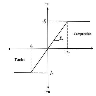
Consider a rectangular beam width of b and depth d subjected to steadily increasing load w over a simply supported span l
Stress stain diagrams shows elastic stress distribution for working and service load hence 
Where f= working stress
Further increases in load caused stress level fy at extreme fiber as shown in fig. This is the limit of elasticity
Therefore elasticity moment of resistance 

For rectangular section 
Further increases in load a does not produce increase in stress as fy remains constant as per idealize stress strain curve but strains increases thus stress is in the fiber immediately below the extreme fiber now reaches to fy
Yielding penetrated inside the fiber this is called elasto plastic range
Further increase in load causes yielding inside the cross section over the depth and the stress distribution is rectangular in both compression as well as tension this stage is known as fully plastic range and the moment at this stage is called plastic range
Moment at fully plastic stage is given by


For rectangular section C = total compressive force
= 
T= total tensile force= 
a = lever arm (y1+y2)
For rectangular section


Where Zp= plastic sectional modulus = 
Concurrently yielding also penetrated is adjoining cross section on either side
Here section
EE fully elastic range/stage
DD elasto plastic range /stage
CC fully plastic range/stage
When yielding of section takes place over entire depth
Section CC behaves similar to mechanical hinge called plastic hinge but at this plastic hinge moment is constant and it is denoted by Mp
Excessive rotation at C due to deformation of plastic hinge transform structure in to mechanism called as collapse mechanism. At this stage load w reaches to wp is called plastic collapse load


Now,
It is seen that rectangular section using equation

Thus the plastic stage rectangular section has 50% more strength compare to that of elastic stage.
Example
A S.S. Beam is determinate she. Formation of one hinge in the beam created collapse mechanism since, the maximum moment under the load the hinge will form at the place.
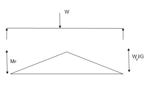

It is ratio of plastic moment carrying capacity (Mp) to the yield moment (Me) of a section. 
Shape factor –
It is defined as the of plastic moment of a section to the yield moment of the section

1. Shape factor for Rectangular section
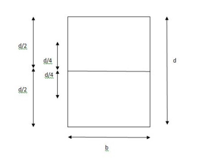
S = 
Zp = 
= 
= 
Z = 
S = = 1.5
= 1.5
Shape factor of 1.5 Rectangular
2. Shape factor of Diamond section
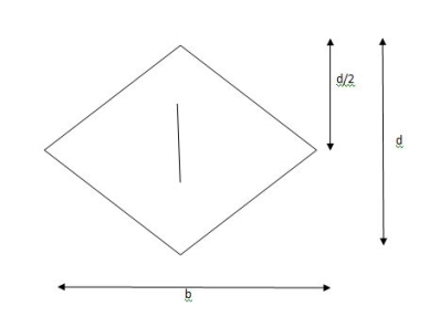
S = 
Zp = 
= 
= 
Shape factor= 2 for Diamond
3. Shape factor for Triangle
Z = 
Diagram
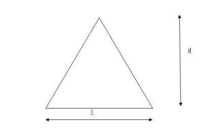
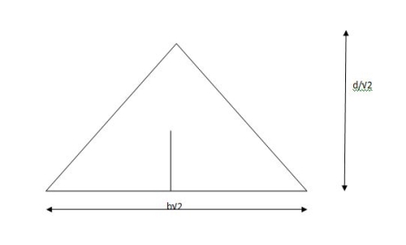
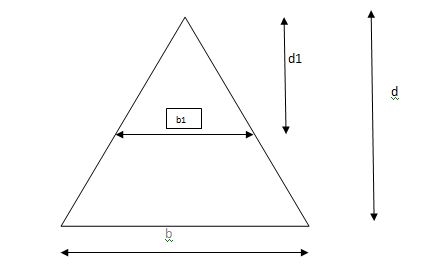
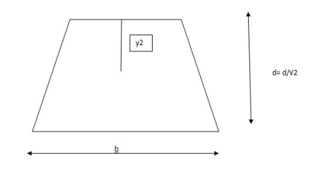
y2 =
y2 = 0.1553
Zp =  ( y1 + y2)

Zp =
S=  = 2.346
Shape factor of triangle = 2.346
4. Shape factor for circular section
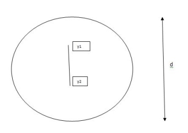
S = 
Z= I/Y =
ZP =
= 
= 
In the mechanism or kinematic approach of plastic analysis, numerous plastic failure mechanisms are evaluated. The plastic fall apart hundreds similar to numerous failure mechanisms are acquired with the aid of using equating the inner paintings on the plastic hinges to the 10W 10 W 6W 2T 3T 5T outside paintings with the aid of using hundreds in the course of the digital displacement. This calls for assessment of displacements and plastic hinge rotations. For gabled frames and different such frames, the kinematics of fall apart is somewhat complex. It is handy to apply the immediate centres of rotation of the inflexible elements of the body to assess displacements similar to one of a kind mechanisms. In this, homes of rotations of a inflexible frame in the course of an infinitesimally small perspective T
Fall apart*L/4. Then (0.50Mp+Mp)+ Pp*L/4, 2 will go together with 2, Mp=(1/6)*Pp*L. The Plastic Load or the fall apart load Pp=6*Mp/L.
- Plastic analysis of determinate beam:
Examples
1. Determine load (Wu) using mechanism method of a simply supported beam subjected to point load at centre.

Solution:
- Number of plastic hinges required to collapse n= r+1 =1
- N=1
- n= N-r= 1
- Using virtual work principle


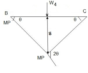
2. Determine collapse load (Wu) of a simply supported beam subjected to eccentric load.

Solution:
- Number of plastic hinge required to collapse n= r+1=1
- N=1
- N=n
- Using virtual work principle


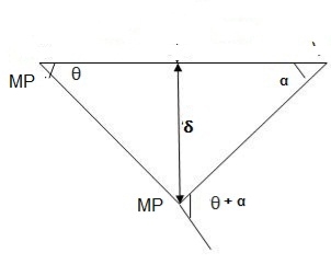
Using virtual work principle


3. Determine collapse load of a simply supported beam subjected to udl over span.

Solution:
- n= r+1=1
- N= 1
- N=n
- Virtual work principle

Average deformation
But 


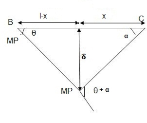
B. Plastic analysis of indeterminate beams
Examples:
1. Determine true collapse load of a propped cantilever beam subjected to load at centre.
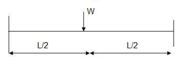
Solution:
- n=r+1 =2
- N=2
- N=n
- Using virtual work principle

But

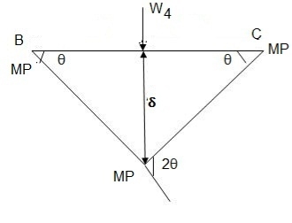
2. Determine true collapse load of a fixed beam subjected to udl

Solution:
- n=r+1= 3
- N=3
- N=n
- Using virtual work principle


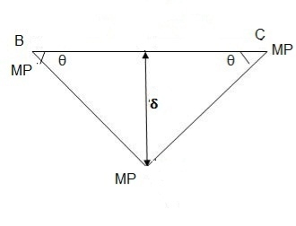
Where Wu= W.L = total UDL
Portal frame
Example:1
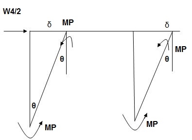
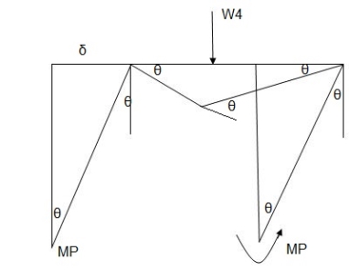
The fig shoes a rectangular portal frame whose legs ase fixed at base. The frame carries a point load W at mid span and a horizontal sway load W/2 Find the value of W at which the frame will collapse all the members are of the same section.
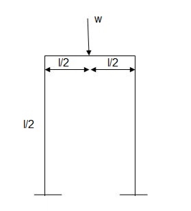
Solution:
- r= 3, n= r+1= 3+1 = 4
- N=5
- N’=N-r= 5-3 =2
- Beam mechanism
Use of virtual work equation


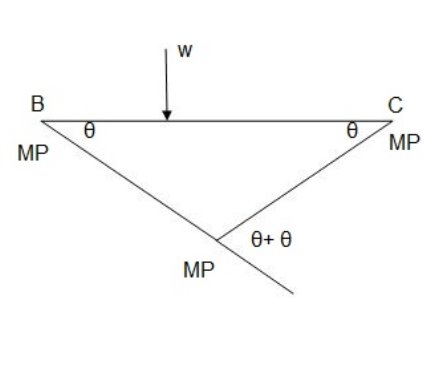
Sway Mechanism


Combined mechanism:


Example: 2
Determine the value of fully plastic moment of the frame when loaded up to collapse as shown in fig. The plastic moment of frame is uniform throughout
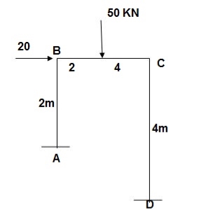
Solution:
- Degree of redundancy r= 3
- n= 3+1 = 4
- N= 5
- N’ = 5-3 = 2
- Mechanism
Beam mechanism:
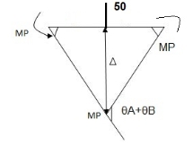


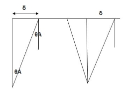
Sway analysis


Combined loading

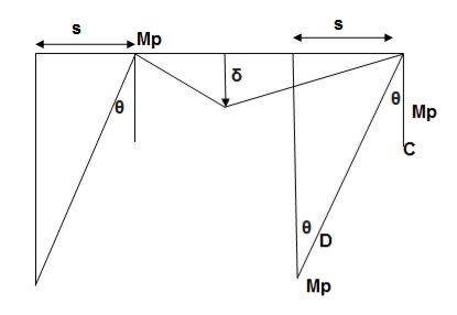


1. Static or Lower Bound Theorem
It states that the if a bending moment distribution can be found which satisfy conditions of equilibrium and yield then the corresponding load must be less than or equal to the true collapse load. This theorem is not much useful and convenient for plastic analysis.
2. Kinematic or Upper Bound Theorem
It states that the collapse load obtained from any assumed mechanism for a given structure must be either greater than or equal to the true collapse load. Here the equilibrium condition is satisfied but not yield condition hence this theorem is called unsafe theorem
3. Uniqueness Theorem
It states that if a bending moment distribution can be obtained which satisfy the three conditions of mechanism, equilibrium and yield, then the collapse load corresponding to such bending moment distribution will be the true collapse load.
The evaluation is primarily based totally at the precept of natural bending. Although this assumption is legitimate for non-stop beams, different secondary outcomes need to be protected within side the evaluation and layout of frames. Secondary outcomes are attributed to a range of things including axial forces, shear forces, buckling (local, lateral, column), repeated loading (fatigue), and brittle fracture. In this text, most effective the impact of axial masses and shear forces can be protected in thinking about a plastic failure in individuals of a structural system. The evaluation of plastic failure is primarily based totally at the concept of small deformations.
If a member is subjected to the blended motion of bending second and axial pressure, the plastic second ability could be reduced. The presence of an axial load means that the sum of the anxiety and compression forces within side the segment isn't zero. This way that the impartial axis movements far from the 35 - 22 same place axis imparting an extra place in anxiety or compression relying on the sort of axial load Consider a square member of width b and intensity d subjected to an axial compressive pressure P collectively with a second M within side the vertical plane. The values of M and P are expanded at a regular price of M/P till the absolutely plastic degree is attained, then the values of M and P become:
Mpa = 0.25 fy b (d2 – 4y2 )
P = 2y u b fy
Where fy = yield stress y = distance from the neutral axis to the stress change for Mp without axial force, Mp = fybd2 /4
If axial force acts alone -Py = fy bd
At the fully plastic state.
From equations the interaction equation can be obtained:
Mx/Mp = 1 – P2 / Py
The presence of shear forces will also reduce the moment capacity.
References:
1. Subramanian N, Design of Steel Structures, Oxford University Press, New Delhi2008.
2. Dayaratnam P, Design of Steel Structures, S. Chand & Co., New Delhi, 2003.
3. Arya, A.S and Ajmani, A.L., Design of Steel Structures, Nemchand and brothers, Roorkee, 1992.
4. Punmia, B.C., Ashok Kumar Jain and Arun Kumar Jain. Comprehensive Design of Steel Structures, Laxmi Publications Pvt. Ltd., New Delhi2000.
5. IS 800-2007, Code of practice for general construction in steel, Bureau of Indian Standards, New Delhi.


