Unit – 2
Connections
Riveted connections:
The riveted connections are these days obsolete. The know-how of this kind of connections for the power assessment and rehabilitation for an older shape is essential. While the relationship technique for riveted connections is equal as that of the bolted connections.
Rivet:
A rivet is made of spherical ductile metallic bar that is known as etc. ‘shank’ and with a head at the only quit. It is made of moderate metallic or excessive tensile metallic.
Riveting:
Riveting is the unique technique of connecting collectively portions of metallic. This technique is carried out through putting the ductile metallic pins known as etc. rivet into the holes of portions to be joined and shaped a head on the quit of the rivet to prevent every metallic piece from coming out.
The shank of the rivet is made of the period to the quantity via the unique elements that is to be linked and with enough greater period for a second head to be made at the opposite quit.
The rivets are commonly categorized as follows:
- Hot pushed rivets: The rivets which might be pushed within side the warm conditions
- Shop rivets: The rivets which might be located in workshop
- Field rivets: The rivets which might be located within side the site/field.
- Cold pushed rivets: Since excessive strain is needed to shape the top at room temperature this kind of rivet is limited.
Clamp movement:
When warm pushed rivets are well cooled down then the diameter and shank period get reduced. Because of this, the compression of the plates happens and those outcomes in friction among the plates, this technique is known as categorized clamp movement.
Disadvantages of riveted connections are as follows:
- It is related to very excessive stage of noise pollution
- There is a want to warmth the rivet until purple warm color.
- Skilled labors are vital to investigate the relationship.
- The fee to get rid of the poorly hooked up rivet could be very excessive.
- The excessive-fee set up within side the connection.
Key takeaways:
- It is related to very excessive stage of noise pollution
- There is a want to warmth the rivet until purple warm color.
- Skilled labors are vital to investigate the relationship.
Bolted Connection:
Most generally used connections consist of the bolted connections. This connection has the benefit of pliability in assembling elements of the shape as well as dissembling it and that is vital if there may be inspection or a few routine maintenances. This kind of connections is relevant for participants subjected to anxiety or shear or each anxiety and shear.
A bolt is a metallic pin with a head shaped at one quit and the shank threaded on the different quit in order that nut may be received. Generally, the bolts are used to attach the portions of metals through putting them via the holes within side the metals; on the threaded quit, nuts ought to be tightened.
The blessings of bolted connections are as follows:
- The technique of erection of shape may be made faster.
- Skilled labors aren't vital.
- Connections do now no longer contain the noise.
- Requirement of labors is less.
- Immediate use of shape is feasible in case of bolted connection.
- The opportunity association of structural participants is feasible if required.
- Lesser running place is needed.
The risks of bolted connections are as follows:
- The cloth fee could be very excessive.
- Due to the place discount at the basis of the thread and because of concentration of pressure, the tensile power of this kind of connection is reduced.
- Bolts get free if it's far subjected to vibrations or shocks.
Classification of bolted connections:
The classifications of bolted connections are made on the premise of resultant pressure transferred, kind of pressure and pressure mechanism.
On the premise of resultant pressure transferred:
- Concentric connections: When the burden of structural member passes via the CG of the segment then this kind of connections are made.
- Eccentric connections: Whenever the ensuring pressure is performing far from the CG of the connections.
- Moment resisting connections: Whenever the connections are subjected to moments.
On the premise of kind of pressure:
- The connections are categorized as shear connections whilst the switch of load passed off via shear. Example: lap joint, butt joint
- Tension connection: Whenever the switch of load passed off via anxiety at the bolts.
- Combined anxiety shear connections: on every occasion the bracket connection is used to join the willing member to the column of the shape.
On the premise of pressure mechanism:
- Bearing kind connections: To switch the pressure bolts under go towards the hole
- Friction kind connections: Due to tensioning of the bolts the pressure is transferred via friction among the plates.
The layout philosophy:
The traditional technique to research the relationship is primarily based totally at the following conditions:
- The deformation of the relationship is omitted because the linked factors of the systems is taken into consideration as inflexible connections
- The connectors used to at technique factors of the segment behave like linear – elastic manner till it fails.
- The ductility belongings of connectors of the systems are unlimited.
In sensible situations, the linked sections like angles, gusset plates, etc. are bendy deformation happens on the low depth of load also.
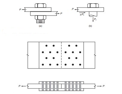
The bearing pressure performing at the bolt is proven at (c) and the shear pressure at (d) and (e). The most shear performing at the bolt, P, happen son the touch surface of the plates. The shear pressure at the bolt on the vital shear aircraft is
Fv= P/Ab
Where
Ab is nominal cross-sectional place of the bolt = pie*d2/4
The slip-vital bolt proven in Fig. 10.3a, relies upon Fl the friction brought about among the linked elements through the clamping movement of the pretension bolts to switch the burden from one linked part to another. No slip happens at carrier hundreds and, as proven at (b), the pressure among the linked plates is transferred through friction.
A lap joint isn't always a desired connection due to the bending stresses produced within side the participants through the eccentricity of the hundreds. A greater appropriate connection is the butt splice and that is proven in Fig. The bolts in a splice joint are in double shear

With two critical shear planes. Hence, each bolt has twice the shear capacity of a bolt in a lap joint. Figure shows a hanger connected by bolts to the bottom flange of a girder. Here the bolts are in tension. An example of a situation where bolts are subjected to combined shear and tension is shown in Fig. In this connection, all bolts are equally loaded in shear. However, because of the eccentricity of the applied load, the top row of bolts also resists tensile stress.
Advantages
1. Connections can be made quickly so that the erection of the structure can be put to use immediately.
2. Less skilled labour required.
3. Making connections/joints is noiseless.
4. Need less labour
5. Accommodates minor discrepancies in dimensions.
6. Expansion and alteration can be done easily.
7. Working area required in the field is less.
Disadvantages
1. Tensile strength is reduced considerably due to stress concentrations and reduction of area at the root of the threads.
2. Cost of material is high about double that of rivets.
3. Rigidity of joints is reduced due to loose fit, hence their strength reduced.
4. Due to vibrations nuts are likely to loosen may danger to the safely of the structures.
Key takeaways:
Connections can be made quickly so that the erection of the structure can be put to use immediately.
Less skilled labour required.
Making connections/joints is noiseless.
Welding is the process of becoming a member of steel quantities within side the molten country without or with pressure.
Electric-arc-welding is typically used.
Part of steel to be welded is melted through the usage of electric powered arc or oxyacetylene flame at the side of a weld rod.
Arc warmth will soften each the steel element and rod on the equal time.
Fusion takes place as welding rod fabric flows throughout the arc.
Welding rod used can be shielded or unshielded.
In the shielded kind, electrode could be lined with mineral compounds (flux) generating a gaseous defend which enables to keep away from oxygen and as a result stabilizing the arc.
Shielded kind improves the fine of work.
Types of welded connection
There are two types of welded connection
Butt weld
Fillet weld
1. Butt weld
Butt weld is also known as groove weld. The various shape of the groove made are
- Square butt weld
- Single V butt weld
- Double V butt weld
- Single U butt weld
- Double U butt weld
The size of butt weld is the effective throat thickness, in case of double butt weld when complete penetration is achieves, the thickness of weld is taken as thickness of thinner plate.
For single butt weld when complete penetration is not achieved the thickness of weld is taken as 5/8 times thickness of thinner plate.
Effective length of butt weld is equal to length of full size weld
Minimum length of weld= 4x size of weld
2. Fillet weld
Fillet weld is approximately triangular cross sectional joining two surfaces which are perpendicular to each other standard fillet weld when the cross section of fillet weld is isosceles triangle.
Minimum size of fillet weld is 3 mm
In drawing only effective length is shown. Actual weld length is equal to effective length + twice the size of weld.
Design strength of fillet weld is

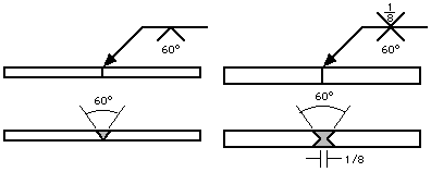
Symbol
1. Fillet welds

The fillet weld (pronounced "fill-it") is used to make lap joints, nook joints and T joints. As its image suggests, the fillet weld is kind of triangular in cross-section, despite the fact that its form isn't always constantly a proper triangle or an isosceles triangle.
Weld metallic is deposited in a nook fashioned through the fit-up of the 2 individuals and penetrates and fuses with the bottom metallic to shape the joint. (Note: for the sake of graphical clarity, the drawings underneath do now no longer display the penetration of the weld metallic. Recognize, however, that the diploma of penetration is essential in figuring out the pleasant of the weld.)
2. Groove welds

The groove weld is usually used to make part-to-part joints, even though it's also regularly utilized in nook joints, T joints, and joints among curved and flat pieces. As recommended via way of means of the type of groove weld symbols, there are numerous methods to make a groove weld, the variations relying typically at the geometry of the components to be joined and the coaching in their edges. Weld steel is deposited inside the groove and penetrates and fuses with the bottom steel to shape the joint.
(Note: for the sake of graphical clarity, the drawings beneath commonly do now no longer display the penetration of the weld steel. The numerous forms of groove weld are:
3. Square groove welds
The groove is created via way of means of both a decent healthy or a moderate separation of the edges. The quantity of separation, if any, is given at the weld symbol
.
4. V-groove welds
The edges of each portion are chamfered, both singly or doubly, to create the groove. The attitude of the V is given at the weld symbol, as is the separation on the root (if any).

Key takeaways:
- The size of butt weld is the effective throat thickness. In case of double butt weld when complete penetration is achieves, the thickness of weld is taken as thickness of thinner plate.
- For single butt weld when complete penetration is not achieved the thickness of weld is taken as 5/8 times thickness of thinner plate.
- Effective length of butt weld is equal to length of full-size weld
- Minimum length of weld= 4x size of weld
Joint Efficiency is a time period utilized in ASME codes for the layout of welded joints in strain vessels. Joint Efficiency refers back to the energy of a welded joint with admire to the energy of the bottom metal.
Concurrently, an performance of 0.50 suggests that the joint has 1/2 of the energy of the bottom metal
Joint Efficiency is a time period utilized in ASME codes for the layout of welded joints in stress vessels. Joint Efficiency refers back to the energy of a welded joint with recognize to the energy of the bottom metallic. A Joint Efficiency of 1.00 (100%) suggests that the weld has the equal energy of the bottom metallic, and it's miles assumed as though it's miles seamless. Concurrently, an performance of 0.50 (50%) suggests that the joint has 1/2 of the energy of the bottom metallic. Joint performance is an essential thing to be taken into consideration within side the layout stage.
When designing the minimal thickness of the shell or the layout stress, the energy of the bottom metallic have to be increased through the Joint Efficiency value. According to ASME, the energy of the welding electrode is best taken into consideration all through the choice of the electrode.
Its energy have to be extra than or identical to the energy of the bottom metallic. If this circumstance is guaranteed, then the layout have to recall the weakest hyperlink within side the chain, that's the bottom metallic.
With that being said, ASME proposes statistical values for this parameter in Table UW-12 primarily based totally at the kind of joint, and the quantity of examination. Joint performance relies upon up on the kind of weld joint and the quantity of the NDT.
Design steps:
Step 1) Design strength of the plate due to rupture of the net section

As bolt are not staggered

Step 2) Design shear strength of the bolt


Step 3) Design bearing strength of the bolt


Step 4) Design strength due to block shear

Examples:
1) Determine the ultimate load carrying capacity in tension of lap joint shown in fig. If bolt threads are outside of the shear plane. Use M16 bolts of product grade C and property class 4.6 the yield and ultimate strengths of the flats are 250 MPa and 410 MPa respectively.
Solution:
Ultimate strength of bolt= 4x100= 400MPa
Since property of class bolt is 4.6
The diameter of the hole (d0) = 16+2 = 18m
- Design strength of the plate due to rupture of the net section

As bolt are not staggered


2. Design shear strength of the bolt


3. Design bearing strength of the bolt


4. Design strength due to block shear
Avg= 2(80 +30)x 12= 2640 mm^2
Avn= 2(80+30-1.5X18) x 12= 1992 mm^2
Atg= 60 x 12= 720 mm^2
Atn= (60-18) x 12 = 504 mm^2


Ultimate load carrying capacity of the joint is the least of


Ultimate load carrying capacity = 148.58 kN
Key takeaways:
- Joint Efficiency is a time period utilized in ASME codes for the layout of welded joints in strain vessels.
- Joint Efficiency refers back to the energy of a welded joint with admire to the energy of the bottom metal.
- Concurrently, an performance of 0.50 suggests that the joint has 1/2 of the energy of the bottom metal
Eccentric Connections
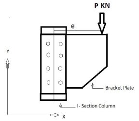
If the force applied does not passes through the CG of the joint then such joint carries moment in addition to an axial direct force. Such types of connections are called as eccentric connections.
Two common loading conditions are discussed in the next two sections, followed by a discussion of the generalized approach for distributing applied loads over a bolt pattern.
- In-Plane Eccentric Shear Load.
- Out-of-Plane Eccentric Shear Load.
- Generalized Approach.
- Bolt Pattern Moments of Inertia.
- Axial Forces.
- Shear Forces.

Connection subjected to eccentric shear
Seat Connections
Framed Connections
Bracket Connections
The connections are categorized as shear connections whilst the switch of load passed off via shear. Example: lap joint, butt joint
Bearing kind connections: To switch the pressure bolts undergo towards the hole
When the bolt is in double shear, cross-sections are powerful in resisting the weight. The bolt in double shear can have the two times the shear power of a bolt in unmarried shear
Moment connection:
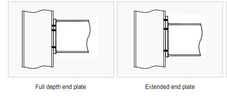
Moment resisting connections are used in multi-story un-braced buildings and in single-story portal body buildings. Connections in multi-story frames are maximum possibly to be bolted, complete intensity quit plate connections or prolonged quit plate connections. Where a deeper connection is needed to offer a bigger lever-arm for the bolts, a hunched connection may be used. However, as extra fabrication will result, this scenario ought to be averted if possible.
For portal body structures, hunched second resisting connections on the eaves and apex of a body are nearly always used, as similarly to presenting extended connection resistances, the haunch will increase the resistance of the rafter.
The maximum generally used second resisting connections are bolted quit plate beam-to-column connections; those are proven within side the parent below.

Instead of bolted beam-to-column connections, welded connections can be used. These connections can provide full moment continuity but are expensive to produce, especially on site. Welded beam-to-column connections can be prepared in the fabrication workshop with a bolted splice connection within the beam spam, at a position of lower bending moment. Welded connections are also used for the construction of buildings in seismic areas.
Other types of moment resisting connections include:
- Splices in columns and beams, including apex connections in portal frames, and
- Column bases.
Bolted beam-to-column connections
Bolted end plate joints between I-section or H-section beams and columns as shown in the figure below are designed using the approach described in BS EN 1993-1-8[1]. Bolted end plate splices and apex connections, which use similar design procedures, are covered in the section on splices.
Key takeaways:
- A plate girder is a metal beam this is broadly utilized in bridge production. Depending at the layout necessities and as according to the character of the structure; steel thicknesses for internet, flanges, stiffness, and many others are decided.
- The use of the right cloth (metal) having the desired electricity and doing the welding are the 2majorelements to be attended to while growing the plate girder.
- A plate girder is used while we want deeper sections having better stiffness to deliver heavy hundreds.
- They may be used to hold heavy hundreds
Examples:
1) A 20 mm thick plate is connected to 18 mm thick plate by 240 mm long butt weld. Determine the strength of joint i) single U butt weld is used ii) double U butt weld is used.
Consider fu= 410N/mm^2
Solution:
Given: Le= 240mm
i) For single U butt weld
As complete penetration is not achieved
t = thickness of weld
= 5/8 X thickness of thinner plate
= 5/8 X 18 = 11.25 mm
Design strength of weld


Total strength of weld


Ii) For Double U butt weld
As complete penetration is achieved
T= thickness of weld= thickness of thinner plate= 18mm
Total strength of weld


Key takeaways:
Step 1) Assume maximum size of weld =S
Thickness of member-1.5 mm
Step 2) calculate design shear strength of weld

Consider fu = 410 MPa if not given
 = 1.25 for shop weld
 = 1.5 field weld
Step 3) calculate strength of weld /mm
= fwd x thickness of weld = fwd (0.7 x S)
Step 4) calculate length of weld required Lw

Step 5) arrange the weld length taking moment of weld length @ c.g. And equating them for equilibrium
References:
1. Subramanian N, Design of Steel Structures, Oxford University Press, New Delhi2008.
2. Dayaratnam P, Design of Steel Structures, S. Chand & Co., New Delhi, 2003.
3. Arya, A.S and Ajmani, A.L., Design of Steel Structures, Nemchand and brothers, Roorkee, 1992.
4. Punmia, B.C., Ashok Kumar Jain and Arun Kumar Jain. Comprehensive Design of Steel Structures, Laxmi Publications Pvt. Ltd., New Delhi2000.
5. IS 800-2007, Code of practice for general construction in steel, Bureau of Indian Standards, New Delhi.