Unit – 3
Tension member
When an anxiety member is subjected to axial tensile pressure, then the distribution of strain over the pass-segment is uniform.
The complete internet place of a member is efficaciously used on the most permissible uniform strain.
Therefore, a tensile member subjected to axial tensile pressure is used to be green and not pricey member.
The method of the layout of an anxiety member is defined under with assist of instance problems.
Tension members are structural elements which are subjected to axial tensile forces. Examples of anxiety members are bracing for homes and bridges, truss members, and cables in suspended roof systems.
In an axially loaded anxiety member, the strain is given by:
F = P/A
Where in P is the importance of the burden and A is the pass-sectional place.
The strain given by this equation is exact, understanding that the pass segment isn't adjoining to the factor of utility of the burden nor having holes for bolts or other discontinuities.
For instance, given an eight x 11 five plate this is used as an anxiety member (segment a-a) and is hooked up to a gusset plate with 7/eight-inch-diameter bolts (segment b-b):
Design
To layout anxiety members, it is crucial to examine how the member might fail beneath Neath each yielding (excessive deformation) and fracture, which can be taken into consideration the restriction states.
The restriction nation that produces the smallest layout energy is taken into consideration the controlling restriction nation.
It additionally prevents the shape from failure.
Using American Institute of Steel Construction standards, the last load on a shape may be calculated from one of the following combinations:
1.4 D
1.2 D + 1.6 L + 0.5 (Lr or S)
1.2 D + 1.6 (Lr or S) + (0.5 L or 0.8 W)
1.2 D + 1.6 W + 0.5 L + 0.5 (Lr or S)
0.9 D + 1.6 W
L= 14
D… is the dead load or the weight of the structure itself
L… is the live load which vary for different structures
S… is the snow load
W… is the wind load
The central problem of designing a member is to find a cross section for which the required strength doesn't exceed the available strength:
Pu < ¢ Pn
Where,
Pu is the sum of the factored loads.
To prevent yielding
0.90 Fy Ag > Pu
To avoid fracture,
0.75 Fu Ae > Pu
Therefore
The design must consider the loads applied to this member, the design forces acting on this member (Mu, Pu, and Vu) and the point where this member would fail.
Example 1: Determine the tensile strength of the 12 mm thick plate shown in Fig Rivets used for the connection are 20 mm diameter. Allowable tensile stress is 150 N/mm2.
Solution
Diameter of the rivet hole = 20 + 1.5 = 21.5 mm
The critical section to be considered is a section like ABCDE.
Effective width at critical section = b – nd = 180 – (3 x 21.5) = 115.5 mm
Effective net area = 115.5 x 12 mm2 = 1386 mm2
Strength of plate = 1386 x 150 = 207900 N = 207.9 kN.
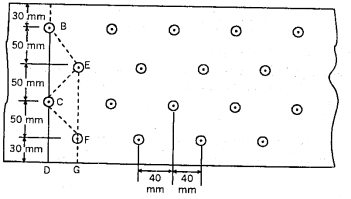
Example 2: Find the strength of the 12 mm thick plate shown in Fig. All the holes are 21.5 mm as gross diameter. Take ft=150 N/mm2.

Solution
Gross diameter of rivet hole = 21.5 mm
The effective net width will be computed along the various chain lines
Staggered pitch p = 40 mm
Gauge distance g = 50 mm
Net width corresponding to the chain ABCD = 210 – (2 x 21.5) = 167 mm
Net width corresponding to the chain ABECFG

Net width corresponding to the chain ABEFG

Net width corresponding to the chain ABECD

Therefore, minimum net width = 148mm
Safe load = Safe stress × Area of minimum net effective section

Design of Tension Member
The following steps can be accompanied within side the layout of axially loaded anxiety participants.
- Corresponding to the loading on the shape of which the anxiety member is a part, the tensile pressure within side the member is first computed.
2. The internet vicinity required for the member is decided via way of means of dividing the tensile pressure within side the member via way of means of the permissible tensile pressure.
3. Now, an appropriate phase having gross vicinity approximately 20 in step with cent to twenty-five in step with cent extra than the predicted vicinity is decided on. For the member decided on deductions are made for the vicinity of rivet holes and the internet powerful vicinity of the phase is decided. If the internet vicinity of the phase of the member so decided is extra than the internet vicinity requirement predicted in step i, the layout is taken into consideration safe.
4. The slenderness ratio of an anxiety member shall now no longer exceed 400. In the case of an anxiety member vulnerable to reversal of pressure because of the motion of wind or earthquake, slenderness ratio shall now no longer exceed 350. If the reversal of pressure is because of masses others than wind or earthquake, the slenderness ratio shall now no longer exceed 180.
5. Gross section yielding:
Steel member (plates, angle) without bolt holes can sustain loads up to the ultimate load without failure. However the member will elongate considerably (10 to 15 % of its original length) at this load and hence make the structure unserviceable.

Where,
Fy = yield strength of the materials in MPa
Ag = gross area of cross section in mm2
6. Net section rupture:
This occurs where tension member connected to the main or other member by bolts or weld. The holes made in members for bolts will reduce the cross section, and hence net area will govern the failure in this case.


Where

w = outstanding lag effect
Bs = shear lag width
For preliminary sizing the rupture strength of net section may be approximately taken as

7. Block shear failure:
Block shear failure considered as a potential failure made at the ends of an axially loaded tension member. In this failure mode, the failure of the member occurs along a path involving tension on one plane and shear on a perpendicular plane along the fasteners.

Where,
Avg= minimum gross and net area
Fu and fu = ultimate and yield stress due to the materials resp.
Key takeaways:
The complete internet place of a member is efficaciously used on the most permissible uniform strain.
Therefore, a tensile member subjected to axial tensile pressure is used to be green and not pricey member.
The method of the layout of an anxiety member is defined under with assist of instance problems.
Tension members are structural elements which are subjected to axial tensile forces.
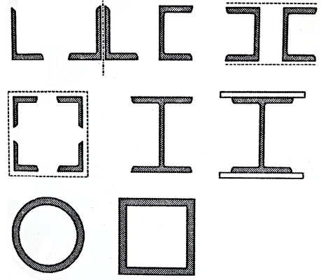
Two or extra than participants are used to shape constructed up participants. When the unmarried rolled metal segment cannot provide the desired area, then constructed-up sections are used. The double attitude sections of unequal legs proven within side the parent is notably used as anxiety participants within side the roof trusses. The attitude sections are positioned lower back to lower back on facets of a gusset plate. When each the attitude sections are connected at the identical facet of the gusset, then constructed-up segment has eccentricity in a single aircraft and is subjected to anxiety and bending simultaneously The attitude sections can be organized within side the big name form (i.e. the angles are positioned diagonally contrary to every different with leg on outer facets). The big name form attitude sections can be related via way of means of batten plates. The batten plates are as a substitute positioned in perpendicular directions. The big name association presents a symmetrical and concentric connection. Two attitude sections as proven within side the parent (a) are used within side the -aircraft trusses in which parallel gussets are used at every connection. Two attitude sections as proven in parent (b) have the gain that the space among them can be adjusted to fit connecting participants at their ends. Four attitude sections as proven in parent (c) also are used within side the -aircraft trusses. The angles are related to 2 parallel gussets. For attitude sections related via way of means of plates as proven in parent (d) are used as anxiety participants in bridge girders.
A built-up phase can be product of channels located lower back to lower back with a gusset in among them. Such sections are used for medium hundreds in a unmarried aircraft-truss. In -aircraft trusses, channels are organized at a distance with their flange became inward. It simplifies the transverse connections and additionally minimizes lacing. The flanges of channels are stored outwards, as withinside the case of chord participants or lengthy span girders, so that it will have extra lateral rigidity. The heavy built-up anxiety participants within side the bridge girder trusses are product of angles and plates. Such participants can face up to compression in reversal of pressure takes place.
Tension member may consist of single structural shape or a built up section. Single angle may be found economical in most of the situation.
However, a single angle with bolted connection will produce eccentricity about both the planes, whereas a single angle with welded end connections may produce eccentricity about one plane only.
Double angle sections are used as a tie member, in a roof truss. The tension member in bridge trusses are made of built-up Channels and I-section.
Tubular members are used in a roof truss. Structural 'T' section may be used as chord members of lightly loaded truss. I-sections, channel sections and built up sections are used in bridges where greater rigidity is required. Rods and bars are used as tension members in the bracing systems. See Fig.

Key takeaways:
- Tension member may consist of single structural shape or a built up section. Single angle may be found economical in most of the situation.
- However, a single angle with bolted connection will produce eccentricity about both the planes, whereas a single angle with welded end connections may produce eccentricity about one plane only.
- Double angle sections are used as a tie member, in a roof truss. The tension member in bridge trusses are made of built-up Channels and I-section.
Examples:
Q.1 Design bolted connection for single angle ISA 90 x 90x 6 mm @ 8.2 kg/m carrying factored axial tension 115 KN with 8 mm thick gusset plate. Use M16 bolt of property class 4.6
Solution:
Given
- Properties of cross section
ISA 90x90x6 mm @ 8.2 kg/m
Ultimate strength of bolt fub= 400 MPa
Ultimate strength of steel fu= 410 MPa


d = 16mm
d0= 18 mm
2. Design of bolted connection
- Shear strength of bolt


b. Bearing strength of bolt
a) 
b) 


Bolt value = least of V dsb and V dpb= 28.97 kN
Number of bolt required = 115/28.97 = 3.96 = 4 bolts
Q.2 A tie member of a truss 2ISA 65x65x6 @ 5.8 kg/m back to back on either side is welded to gusset plate. Design a weld to transmit a load equal to the full strength of the member.
Solution:
- Design tensile strength due to yielding of gross cross section

2. Design of welded connection
From table 21 IS 800-2007
Assume size of weld= 6 mm
By equating,


But

Taking moment about C.G


By using equation


References:
1. Subramanian N, Design of Steel Structures, Oxford University Press, New Delhi2008.
2. Dayaratnam P, Design of Steel Structures, S. Chand & Co., New Delhi, 2003.
3. Arya, A.S and Ajmani, A.L., Design of Steel Structures, Nemchand and brothers, Roorkee, 1992.
4. Punmia, B.C., Ashok Kumar Jain and Arun Kumar Jain. Comprehensive Design of Steel Structures, Laxmi Publications Pvt. Ltd., New Delhi2000.
5. IS 800-2007, Code of practice for general construction in steel, Bureau of Indian Standards, New Delhi.