Unit – 5
Flexural members
Beams are structural elements subjected to transverse loads in the plane of bending causing bending moments and shear forces.
Symmetrical b sections about z-z axis (major axis) are economical and geometrical properties of such sections are available in SP (6).
The compression flange of the beams can be laterally supported (restrained) or laterally unsupported (unrestrained) depending upon whether restraints are provided or not.
The beams are designed for maximum BM and checked for maximum SF, local effects such as vertical buckling and crippling of webs and deflection. Section 8 (IS 800-2007) shall be followed in the design of such bending members.
Types of Sections
Beams can be different cross sections depending on the span and loadings.
1. Simple I section
2. I section with cover plate
3. Two I section with cover plate
4. Built-up I section
5. Gantry girder
6. Box sections
7. Castled beams
8. Two I placed one above the other
1) Simple I section: Use of simple I section is normal span and loading
2) I section with cover plate: Use of I section with cover plate is heavy load and larger span
3) Two I section with cover plate: it is use of very heavy load with large span
4) Built-up I section: it is used to plate girder where span exceed 20 m and loads are heavy.
5) Gantry girder: Gantry girder is use for movable heavy loads, lift loads etc.
6) Box sections: It is use for service lines
7) Castled beams: It is use for light loads and large span
8) Two I placed one above the other: It is used for light loading with large span
Behaviour of Beam in Flexure
In order to expect the flexural behavior of any brittle fabric like concrete, load deflection technique on 3 factors become essential. The 3 factor technique is the manner to compute the deflections because of implemented masses so as to investigate the flexural behavior.
RCC beam are efficiently used as structural participants in diverse constructions. RCC is a homogeneous material which is having diverse properties.
RCC beams are classified as under strengthened, balanced and over strengthened sections on the evaluation basis. In RCC each concrete and steels will reaches the pressure and corresponding lines because of outside subjected hundreds concurrently.
When in an RCC beam, if the metallic has a tendency to fail earlier than the pressure in concrete reaches the maximum permissible pressure such beams are known as under strengthened sections. If each concrete and metallic reaches the permissible pressure values concurrently such beams are taken into consideration as balanced sections. If the concrete has a tendency to fail earlier than the pressure in metallic reaches the maximum permissible pressure such beams are taken into consideration as over strengthened sections. In the following article primarily based totally on the laboratory experimental evaluation the flexure behavior of diverse sections are discovered through damaging methods.
DESIGN CRITERIA
The primary layout criterion for any form of shape is safety, serviceability and economy. Due to these primary esteem properties of RCC elements, they are abundantly used in all structural applications. For the structural use of RCC elements it must obey the following parameters. The shape must be secure and economical that it can perfectly resist both tension and compressive stress. The shape must be stiff and look like unblemished such that it ought to be resisted the bending moments and shear forces because of outside applied masses.
The shape must be economical by means of it can be able to resist all type of stress and availability of substances to make RCC. In order to are expecting the secure and monetary situations of RCC it's far essential to evaluate the situations of remaining masses and corresponding deflections below precise constrains.
To attain the applicable outcomes one had to behavior an experimental analysis. When an RCC beam is subjected to a few outside loadings the beam tends to bend with a few deflection due to loading. At any point in the cross section of the beam is considered the pressure distribution can be such that everyone the fibers above the impartial axis by skip thru the CG are in compression, while all of the fibers beneath the impartial axis are in tension.

Key takeaways:
1) RCC beam are efficiently used as structural participants in diverse constructions. RCC is a homogeneous material which is having diverse properties.
2) RCC beams are classified as under strengthened, balanced and over strengthened sections on the evaluation basis.
3) In RCC each concrete and steels will reaches the pressure and corresponding lines because of outside subjected hundreds concurrently.
Classification of cross section
Cross section | Limit | Buckling about axis | Buckling class |
Rolled I section | h/bf>1.2:tf<40mm 40<mm<tf<100mm | z-z y-y z-z y-y | A B B C |
Welded I section | Tf<40mm Tf>40mm | z-z y-y z-z y-y | b c c d |
Hollow section | Hot rolled | Any | a |
| Cold rolled | Any | B |
Welded box section | Generally (expected as below) | Any | B |
| Thick welds and b/tf<30 h/tf<30 |
z-z y-y |
c c |
Channel, angle, T and Solid sections |
| Any | C |
Built up member |
| Any | c |
A built-up beam is likewise referred to as compound beam.
The built-up beams are used whilst the span, load and corresponding bending second are of such magnitudes that rolled metal beam segment will become insufficient to offer required segment modulus.
Built-up beams also are used whilst rolled metal beams are insufficient for restricted intensity.
In constructing construction, the intensity of beam is restricted with the aid of using an area furnished with the aid of using the architect.
Drawing beam of small intensity do now no longer offer required segment modulus. Therefore, plates are connected to the beams.
The energy of rolled metal beams is multiplied with the aid of using including plates to its flange that's one of the techniques forming built-in segment.
The different technique is to compound some of rolled metal sections themselves.
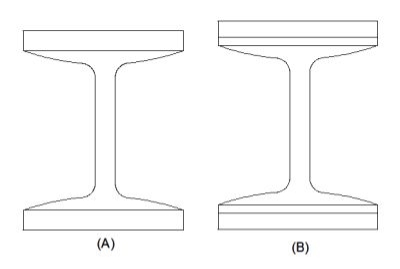
The built-up sections shown in figure’ A’ and ‘B’ are used for heavy loads and small spans.
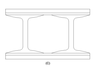
The built-up section ‘C’ is also used for heavy loads and small span.
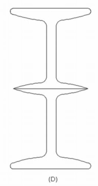
The built-up section ‘D’ is used for light loads and large spans.
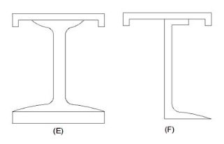
The built-up sections ‘E’ & ‘F’ are provided for Gantry girders.
Design Procedure of the Built-up Beams design
In my earlier articles, we discussed in detail about the “Theory of Built-up Beams “. In this article, we will move a step ahead and understand the concept of the design of Built-up beams.
Here are the simple steps that are to be followed for the design of Built-up Beams.
Step one
The effective span and load required to be carried by the built-up beam are known.
Maximum bending moment and shear force in built-up beams are calculated.
Step two
Value of yield stress (fy) for structural steel is to be assumed.
The permissible bending stress (sigma bc) is calculated.
Step three
The required section modulus (Z) for the given beam section is calculated.
Step four
From the steel table, a trial section for a beam is adopted having the modulus of section (Z) about 25% to 50% in excess of that requirement. The geometrical proportion of beam sections are noted.
Step five
When the depth of the beam is noted, then the usually the practice is to select from ISI handbook No.1 (Steel tables).
The strongest Rolled steel beam that will allow for necessary thickness of power plates at top and bottom.
Step six
The area of power plate required is found out by trial-and-error method are by;
I = Ibeam + 2(Ap)(h/2) (h/2)
For finding the area, divide the whole equation by h/2.
Step seven
Width of cover plate and thickness are decided with the restriction of outstands.
Step Eight
Check for bending stress/Actual bending compressive stress
(Sigma bc) calculated = (maximum bending moment/Gross MI) x Distance of extreme fibre in compression from Neutral Axis
= (M/Ixx) x y1
Actual bending tension stress
Sigma bt, cal = (sigma bc) cal x (gross area of tension flange/Net area of tension flange)
= Value should not exceed the permissible bending stress (sigma bc) or (sigma bt) = 0/66fy
Step nine
Check for shear and Deflection
Shear strength:
Shear forces always exists with BMS and the maximum shear stress has to be checked with the shear yield stress. Shear stresses can become important if the depth of the beams are restricted and when beams are subjected to large concentrated loads near the supports The distribution of shear stress at limit state (plastic) is shown below
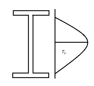
The nominal shear yielding strength is based on the Von Mises yield criteria which assumes wide and thin webs without any local failures. The shear strength is expressed as

Fyw = yield strength of the web
The design strength

Av = Shear area as specified in cl. 8.4.1.1 pg-59
The web can buckle elastically or in elastically depending on the ratio of d/tw if this ratio exceeds 67E
Where,
€ =  and d = clear depth of the web between flanges, resistance to shear buckling has to be verified
Shear failure can occur due to excessive yielding of the web area if the shear capacity is exceeded. The beam will be a high shear condition if V > 0.6 V, and the moment capacity of the section decreases and has to calculated using the provisions given in cl. 9.2.2 pg 70.
Bending Strength of Beams
The design of beam consist of selecting a section based on plastic sectional modulus and checking for its shear capacity deflection, web crippling and web buckling. Most of equation available in IS 800-2007
Design bending strength
1) If V> 0.6Vd
Or
V< 0.6Vd
Then

For simply supported beams

Where,


2) If V>0.6Vd
Then Md= Mdv
Where
Md= Design of bending strength under high shear

For plastic and compact sections
= 

Bearing Strength
The design bearing strength of a bolt on any plate Vdpb as governed by bearing is given by

Where
Vnpb= nominal bearing strength of a bolt

Where
Kb is smaller of e/3do, p/3do-0.25 or 1.0
The bearing resistance (in the direction normal to the slots in slotted holes) of bolts in holes other than standard clearance holes may be reduced by multiplying the bearing resistance obtained as above
Key takeaways:
1) Shear forces always exists with BMS and the maximum shear stress has to be checked with the shear yield stress.
2) Shear stresses can become important if the depth of the beams is restricted and when beams are subjected to large concentrated loads near the supports.
3) Shear failure can occur due to excessive yielding of the web area if the shear capacity is exceeded. The beam will be a high shear condition if V > 0.6 V
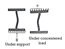
Web crippling causes local crushing failure of web due to large bearing stresses under reactions at supports or concentrated loads. This occurs due to stress concentration because of the bottle neck condition at the junction between flanges and web. It is due to the large localized bearing stress caused by the transfer of compression from relatively wide flange to narrow and thin web. Web crippling is the crushing failure of the metal at the junction of flange and web. Web crippling causes local buckling of web at the junction of web and flange.
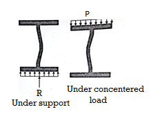
For safety against web crippling, the resisting force shall be greater than the reaction or the concentrated load. It will be assumed that the reaction or concentrated load is dispersed into the web with a slope of 1 in 2.5 as shown in the Fig.
Let Resisting force = Fwc
Thickness of web = tw
Yield stress in web = fyw
Width of bearing plate = b₁
Width of dispersion = n₂

For concentrated loads, the dispersion is on both sides and the resisting force can be expressed as,

Key takeaways:
Web crippling causes local crushing failure of web due to large bearing stresses under reactions at supports or concentrated loads.
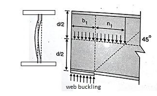
The web of the beam is thin and can buckle under reactions and concentrated loads with the web behaving like a short column fixed at the flanges. The unsupported length between the fillet lines for sections and the vertical distance between the flanges or flange angles in built up sections can buckle due to reactions or concentrated loads. This is called web buckling.
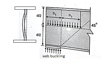
For safety against web buckling. The resisting e shall be greater than the reaction or the concentrated load. It will be assumed that the reaction concentrated load is dispersed into the web at 45" as shown in the Fig.
Let Resisting force F
Thickness of web = t
Design compressive stress in web =fcd
Width of bearing plate= b1
Width of dispersion = n1

For concentrated loads, the dispersion is on both sides and the resisting force can be expressed as, Fwb = [(b₁ +2 n₁) tw fcd] ≥ Concentrated load, P
The design compressive stress fd is calculated based on a effective slenderness ratio of 
Where,
d = clear depth of web between the flanges
Ry = radius of gyration about y-y axis and is expressed as,


Design compressive stress in web, fcd for the above slenderness ratio is obtained from curve, C (Buckling class C) (Table 9c, pg 42)
Key takeaways:
The web of the beam is thin and can buckle under reactions and concentrated loads with the web behaving like a short column fixed at the flanges.
Stiffeners are secondary plates or sections that are connected to beam webs or flanges to stiffen them in opposition to out of aircraft deformations. Almost all important bridge beams may have stiffeners. However, maximum will most effective have transverse net stiffeners, i.e. vertical stiffeners connected to the net. Deep beams from time to time additionally have longitudinal net stiffeners. Flange stiffeners can be used on huge span field girder bridges however are not likely to be encountered elsewhere.
Types of stiffener
There are fundamental kinds of stiffener: Longitudinal net stiffeners, which might be aligned within side the span route Transverse stiffeners, which might be aligned ordinary to the span route of the beam.
Transverse internet stiffeners are generally supplied at bearing positions and those are referred to as bearing stiffeners. For destiny preservation it is ideal exercise to offer bearing stiffeners at jacking points (for whilst girders ought to be raised to unfastened bearings for replacement). Other transverse stiffeners are known as intermediate transverse internet stiffeners.
Stiffener sections A kind of sections were traditionally used as stiffeners, but the easy flat stiffener is the kind nearly continually utilized in present day designs. Stiffeners may be connected on one aspect of the plate (unmarried sided), or on each sides (double sided). Usually bearing stiffeners are double sided, even as intermediate internet stiffeners are unmarried sided. Stiffeners also can be doubled up, or maybe trebled, to shape multi-leg stiffeners.
Members difficulty to big focused hundreds inside their period or big cease reactions have to be proportioned in order that the forces at the net or flange can not purpose neighbour hood failure or the webs or flanges have to be stiffened to hold the focused hundreds. Both ASD and LRFD processes consist of layout criteria. ASD for Load-Bearing Stiffeners Webs of rolled beams and plate girders have to be so proportioned that the compressive stress, ksi, on the net toe of the fillets does now no longer exceed Fa = 0.66Fy wherein Fy = distinctive minimal yield stress, ksi. Web failure possibly might be within side the shape of buckling because of focused loading, both at an indoors load or on the supports. The capability of the net to transmit the forces correctly have to be checked. Load Distribution. Loads are resisted now no longer most effective through the a part of the net immediately beneath them however additionally through the elements straight away adjacent. A forty five distribution typically is assumed, as indicated for 2 not unusual place conditions. The distance okay is decided by the time wherein the fillet of the flange joins the net; it's miles tabulated within side the beam tables of the AISC ‘‘Manual of Steel Construction.’’ Fa is relevant to the horizontal net strip of period b okay on the cease help or b 2k beneath an indoors load. Bearing stiffeners are required while Fa is exceeded.
Examples:
1) A simply supported beam of effective span 4 m carries a factored point load of 350 kN at mid span. The section is laterally supported throughout the span. Design the cross section using I section.
Solution:
- Maximum shear force
V= reaction = W/2 = 1575 kN
2. maximum bending moment
M= WL/4= 350 kn-m
3. selection of cross section (using yielding criteria)
Zp required = 

Select an ISLB 500@75kg/m (using annex H Is 800-2007)
Sectional properties d=500 mm, Izz= 38549 x 1064 mm^4
Zp= 1773.7x 10^3 mm^3 > Zp required
Ze= 1545.2 X 10^3 mm^3
4. classification of section


5. Design shear strength


6. Design bending strength


7. Checks
- Web buckling

At a concentrated load W


Buckling class C
From table 9© IS 800-2007 and fy= 250 Mpa
Kl/r | Fcd |
130 | 74.3 |
131.78 | ? |
140 | 66.2 |
Interpolation
Fcd= 72.85 N/mm^2
At concentrated point load


At reaction R


B. Web crippling


C. Deflection limits
Working load = 350/1.5 = 233.33kN


Provide an ISLB 500@ 75 kg/m beam
References:
1. Subramanian N, Design of Steel Structures, Oxford University Press, New Delhi2008.
2. Dayaratnam P, Design of Steel Structures, S. Chand & Co., New Delhi, 2003.
3. Arya, A.S and Ajmani, A.L., Design of Steel Structures, Nemchand and brothers, Roorkee, 1992.
4. Punmia, B.C., Ashok Kumar Jain and Arun Kumar Jain. Comprehensive Design of Steel Structures, Laxmi Publications Pvt. Ltd., New Delhi2000.
5. IS 800-2007, Code of practice for general construction in steel, Bureau of Indian Standards, New Delhi.