Unit – 1
Introduction
Database
The database is a set of interrelated data used to efficiently retrieve, insert and remove data. It is also used in the form of a table, schema, views, and reports to organise the data, etc.
You can conveniently retrieve, attach, and delete information using the database.
Database management system (DBMS)
A DBMS is a programme that enables database creation, specification and manipulation, allowing users to easily store, process and analyse information.
DBMS provides one with an interface or a tool to conduct different operations, such as building databases, storing data in them, updating data, creating database tables, and much more.
The DBMS also provides databases with privacy and security. In the case of multiple users, it also ensures data consistency.
Some Example of DBMS:
● MySql
● Oracle
● SQL Server
● IBM DB2
Characteristics of DBMS
● Data stored into tables
● Reduced redundancy
● Query language
● Data consistency
● Security
● DBMS support transactions
● Support multiple user and concurrent access
Key takeaway:
- You can conveniently retrieve, attach, and delete information using the database.
- The DBMS provides databases with privacy and security.
- In the case of multiple users, it also ensures data consistency.
Difference between DBMS and file system, are as follows:
DBMS | File System |
A database management system is a collection of data. The user is not allowed to write procedures in a DBMS. | A file system is a data storage system. The user must write the database management procedures in this method. |
A database management system provides an abstract view of data that hides the information. | The data representation and storage of data are detailed in the file system.
|
A crash recovery mechanism is provided by DBMS, which protects the user from device failure. | The file system lacks a crash mechanism, which means that if the system crashes when entering data, the file's content will be lost. |
A good security mechanism is provided by DBMS. | Under the file system, protecting a file is extremely difficult. |
A database management system provides a broad range of advanced techniques for storing and retrieving data. | The file system is incapable of effectively storing and retrieving data. |
Concurrent data access is handled by DBMSs using some kind of locking.
| Concurrent access in the File system causes a number of issues, such as redirecting the file when others delete or update data. |
The architecture of a database management system influences its design. When dealing with a large number of PCs, web servers, database servers, and other networked elements, the same client/server architecture is used.
A client/server architecture is made up of several PCs and a workstation that are all linked by a network.
The design of a database management system is determined by how users link to the database in order to complete their requests.
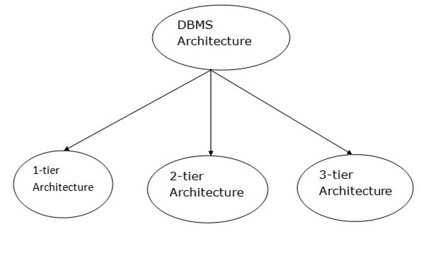
Fig 1: Types of architecture
A single tier or multi-tier database architecture can be seen. However, database design can be divided into two categories: 2-tier architecture and 3-tier architecture.
1-tier Architecture:
The database is directly accessible to the user in this architecture. It means that the user can sit on the DBMS and use it directly. Any modifications made here will be applied directly to the database. It does not provide end users with a useful tool.
For the creation of local applications, a 1-tier architecture is used, in which programmers can interact directly with the database for fast responses.
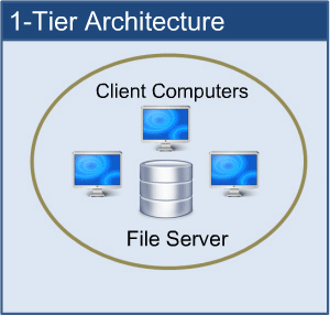
Fig 2: 1-tier architecture
2-tier Architecture:
The 2-tier architecture is similar to the basic client-server architecture. Client-side applications can interact directly with the database on the server side in a two-tier architecture. APIs such as ODBC and JDBC are used for this interaction.
The client-side runs the user interfaces and application programs. The server side is in charge of providing features such as query processing and transaction management. The client-side application creates a link with the server side in order to communicate with the DBMS.
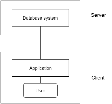
Fig 3: 2-tier architecture
3-tier Architecture:
Between the client and the server is another layer in the 3-tier architecture. The client cannot communicate directly with the server in this architecture. The client-side program communicates with an application server, which in turn communicates with the database system.
Beyond the application server, the end user is unaware of the database's presence. Aside from the submission, the database has no knowledge about any other users.
In the case of a wide web application, the 3-tier architecture is used.
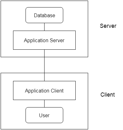
Fig 4: 3-tier architecture
● An instance of the database is the data that is stored in the database at a specific point in time.
● Schema refers to a database's overall configuration.
● A database schema is the database's skeleton structure. It reflects the entire database's logical view.
● Tables, foreign keys, primary keys, views, columns, data types, stored procedures, and other schema objects are included in a schema.
● The visual diagram can be used to describe a database schema. This diagram depicts the database objects and their relationships.
● Database schemas are created by database designers to assist programmers who will be working with the database. Data modeling is the term for the method of creating a database.
Only certain elements of a schema, such as the name of the record type, data type, and constraints, can be shown in a schema diagram. The schema diagram does not allow for the specification of other aspects. The provided figure, for example, does not indicate the data form of each data item or the relationship between the different files.
Actual data in the database is updated on a regular basis. When we add a new grade or a student, for example, the database shifts as seen in the diagram. The database instance refers to the data at a certain point in time.
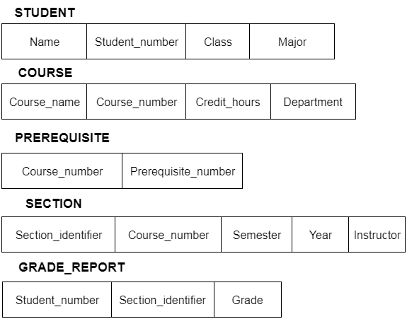
Fig 5: Schema diagram
In addition to users' data, a database system usually includes a lot of data. For instance, to easily locate and retrieve data, it stores information about data, known as metadata. Modifying or modifying a collection of metadata once it is placed in the database is very difficult. But when a DBMS expands, in order to fulfil the users' requirements, it needs to evolve over time. It will become a boring and highly complicated job if the entire data is based.
Metadata itself follows a layered model, such that it does not impact the data at another level when we modify data on one layer. This data is independent, but is mapped to one another.
Types of data independences
● Physical data independence
Physical Data Independence is defined as the ability to make adjustments without affecting the higher-level schemas in the structure of the lowest level of the Database Management System (DBMS). Therefore, the Physical level adjustment does not result in any adjustments to the Conceptual or View levels.
● Logical data independence
Logical Data Independence is defined as the ability to make improvements to the Database Management System (DBMS) middle level structure without affecting the schema or application programmes at the highest level. Changes to the conceptual level should also not result in any changes to the view levels or programmes of the application.
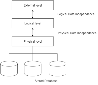
Fig 6: Data independence
Database language:
Users can interact with DBMS using database languages. There are two types of database languages:
1. The Data Definition Language (DDL)
2. The Data Manipulation Language (DML)
Interfaces
● Menu-based interfaces for Web clients or browsing
● Forms-based interfaces
● Graphical user interfaces
● Natural language interfaces
● Speech input and output
● Interfaces for parametric users
● Interfaces for the DBA
Key takeaway:
- The freedom of logical data refers to the ability to alter the conceptual schema without the external schema needing to be modified.
- Independence of physical data can be defined as the ability to alter the internal schema without the conceptual schema having to be modified.
In reality, the DDL or Data Definition Language consists of SQL commands that can be used to define the schema for the database. It basically deals with database schema definitions and is used to construct and change the configuration of database objects in the database.
Some of the commands that fall under DDL are as follows:
● CREATE
● ALTER
● DROP
● TRUNCATE
CREATE
It is used in the database for the development of a new table
Syntax
CREATE TABLE TABLE_NAME (COLUMN_NAME DATA TYPES[,....]);
Example
CREATE TABLE STUDENT(Name VARCHAR2(20), Address VARCHAR2(100), DOB DATE);
ALTER
It is used to modify the database structure. This move may be either to change the characteristics of an existing attribute or to add a new attribute, likely.
Syntax
In order to add a new column to the table:
ALTER TABLE table_name ADD column_name COLUMN-definition;
To change the current table column:
ALTER TABLE MODIFY(COLUMN DEFINITION....);
Example
ALTER TABLE STU_DETAILS ADD(ADDRESS VARCHAR2(20));
ALTER TABLE STU_DETAILS MODIFY (NAME VARCHAR2(20));
Drop
It is used to delete both the structure of the table and the record.
Syntax
DROP TABLE;
Example
DROP TABLE STUDENT;
TRUNCATE
It is used to erase from the table all rows and free up the space containing the table.
Syntax
TRUNCATE TABLE table_name;
Example
TRUNCATE TABLE STUDENT;
Data Manipulation Language (DML)
To change the database, DML commands are used. It is responsible for all forms of database changes.
The DML command is not auto-committed, which means all the changes in the database will not be permanently saved. There may be rollbacks.
Commands under DML
a. INSERT
The INSERT statement is a query from SQL. It is used for the insertion of data into a table row.
Syntax
INSERT INTO TABLE_NAME
(col1, col2, col3,.... Col N)
VALUES (value1, value2, value3, .... ValueN);
Or
INSERT INTO TABLE_NAME
VALUES (value1, value2, value3, .... ValueN);
b. UPDATE
This command is used to update or alter the value of a table column.
Syntax
UPDATE table_name SET [column_name1= value1,...column_nameN = valueN] [WHERE CONDITION]
c. DELETE
It is used to extract a table from one or more rows.
Syntax
DELETE FROM table_name [WHERE condition];
Types of DML: -
a. Procedural: -
It requires a user to specify what data is needed and how to retrieve it from the database. The user instructs the system to perform a sequence of options on the database to compute the desired result.
b. Non-Procedural: -
It requires a user to specify what data is needed without specifying how to get it.
Key takeaway:
- The DDL or Data Definition Language consists of SQL commands that can be used to define the schema for the database.
- To change the database, DML commands are used. It is responsible for all forms of database changes.
- The DML command is not auto-committed, which means all the changes in the database will not be permanently saved.
A system of databases is divided into modules dealing with each of the overall system's responsibilities. A database system's functional components can be narrowly divided into the components of the storage manager and the query processor. The storage manager is essential since a large amount of storage space is usually needed for databases. The query processor is important because it simplifies and promotes access to data by supporting the database system.
It is the responsibility of the database system to convert, at the logical level, changes and queries written in a non-procedural language into an effective sequence of physical level operations.
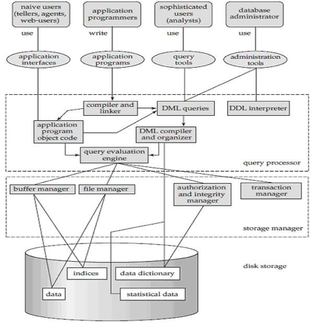
Fig 7: Overall structure of DBMS
The database system is divided into three components: Query Processor, Storage Manager, and Disk Storage
● Query processor
It interprets the requests (queries) received from the end user into instructions through an application programme. Also, the user request that is received from the DML compiler is executed.
The Query Processor comprises the following parts:
● DML compiler
The DML statements are processed into low-level (machine language) instructions so that they can be implemented.
● DDL interpreter
The DDL statements are processed into a table set containing metadata (data about data).
● Query optimization
Typically, a question can be converted into any of a variety of alternative assessment plans that all offer the same outcome. The DML compiler also performs query optimization, which is to say, among the alternatives, it selects the lowest cost evaluation plan.
● Query evaluation engine
That executes the low-level instructions that the DML compiler generates.
● Storage manager
A storage manager is a software module that provides an interface between the low-level data stored in the database and the system-submitted application programmes and queries. Interaction with the file manager is the responsibility of the storage manager. Using the file system, which is typically supported by a conventional operating system, raw data is stored on the disc. The storage manager converts the different DML statements into low-level commands for the file system. It is also the duty of the storage manager to store, retrieve, and update data in the database.
The components for the storage manager include:
● Authorization and integrity manager
This ensures role-based regulation of access, i.e., It checks whether or not the individual is entitled to conduct the requested activity.
When the database is updated, the integrity manager checks the integrity constraints.
● Transaction manager
It manages simultaneous access by executing the operations in a scheduled manner in which the transaction is received. It also ensures that the database stays in a consistent state before and after a transaction has been executed.
● File manager
It manages the space of the file and the data structure used in the database to represent information.
● Buffer manager
The cache memory and data transfer between the secondary storage and the main memory are responsible for this.
● Disk storage
It includes the following elements-
● Data files
It stores the data.
● Data dictionary
It includes details about any database object's structure. It is the information repository that regulates metadata.
● Indices
It provides faster retrieval of data items.
Key takeaway:
- A database system's functional components can be narrowly divided into the components of the storage manager and the query processor.
- A system of databases is divided into modules dealing with each of the overall system's responsibilities.
- The storage manager converts the different DML statements into low-level commands for the file system.
● The Entity-Relationship model (ER model) is a type of entity-relationship model. It's a data model at a high level. The data elements and relationships for a given system are described using this model.
● It creates a database's conceptual architecture. It also creates a very convenient and easy-to-design data view.
● The database structure is depicted as a diagram called an entity-relationship diagram in ER modeling.
Let's say we're creating a database for a school. The student will be an object in this database, with attributes such as address, name, id, age, and so on. There will be a relationship between the address and another entity with attributes such as city, street name, pin code, and so on.
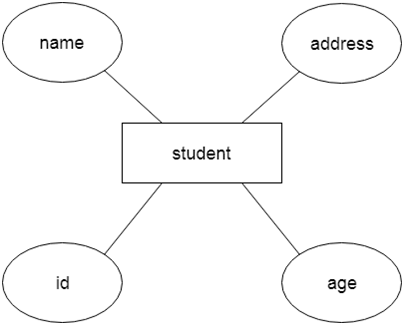
Fig 8: Example of ER
Component of ER model -
The following components are composed of an ER Diagram:
- Entity
- Attributes
- Relationships
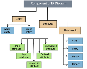
Fig 9: Component of ER model
1.Entity
The object, location, person, or event that stores data in the database may be an entity. In an object-relationship diagram, a rectangle represents an entity.
Examples of an individual include a student, course, boss, employee, patient, etc.

Fig 10: Entity
Entity type:
A list or a set of entities having certain common attributes is an entity type. In a database, a name and a list of attributes define each type of entity.
Entity set:
It is a set (or collection) of entities of the same kind that share attributes or related properties.
For example, it is possible to describe the category of individuals who are lecturers at a university as an entity-set lecturer. Similarly, the collection of students of the organization could represent the community of all university students.
2.Attribute
In an Entity-Relationship Model, an attribute defines an entity's properties or characteristics. It is represented in the ER diagram by an oval or ellipse shape. Each oval shape represents one attribute and is directly linked to the person that is in the shape of the rectangle.
For instance, the attributes defining the Employee form of entity are employee id, employee name, gender, employee age, salary, and mobile no.
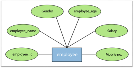
Fig 11: Different attributes of employee
In the ER model, the following categories can be defined by an attribute:
1.Simple attribute:
A simple attribute is called an attribute which contains an atomic value and can not be divided further. The gender and salary of a worker, for instance, is also depicted by an oval.
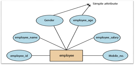
Fig 12: Simple attribute
2. Key attribute:
A key attribute is called an attribute that can uniquely identify an entity in an entity set. It represents a primary key in the ER diagram. In an Entity Relationship diagram, the key attribute is denoted by an oval with an underlying line. For example, for each employee, the employee id would be unique.
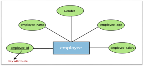
Fig 13: Key attributes
3. Composite attribute:
An attribute that is a combination of two or more basic attributes is called a composite attribute. It is defined by an ellipse in an Entity-Relationship diagram, and that ellipse consists of other ellipses. For example, an employee entity type's name attribute consists of first name, second name, and last name.
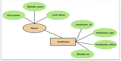
Fig 14: Composite attribute
4.Derived attribute:
A derived attribute is considered an attribute which can be derived from other attributes. In an entity-relationship diagram, a dashed oval shape is used to represent these attributes. Employee age is, for example, a derived attribute since it varies over time and can be derived from another DOB attribute (Date of birth).
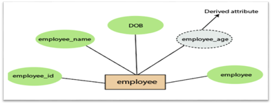
Fig 15: Derived attribute
5.Multivalued attributes:
An attribute which for a given entity contains more than one value. For instance, there may be more than one mobile number and email address for an employee.
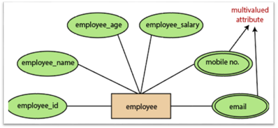
Fig 16: Multivalued attribute
3.Relationship
In the Entity-Relation Model, a relationship is used to define the relationship between two or more entities. In the ER diagram, it is illustrated by a diamond shape.
For example, in college student studies, employees work in a department. Here, the links are 'research in' and 'works in'.
Degree of Relationship
A partnership is called the degree of a relationship in which a variety of different individuals participate.
Degree of relationship can be categorized into the following types:
1. Unary Relationship:
A relationship in which a single group of individuals is involved is referred to as a unary relationship. For instance, in a company, an employee manages or supervises another employee.
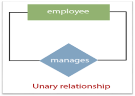
Fig 17: Unary relationship
2. Binary Relationship: When a relationship includes two people, it is considered a binary relationship.
3. Ternary Relationship: When a relationship contains three individual sets, a ternary relationship is called.
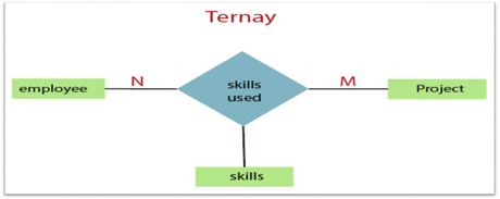
Fig 18: Ternary relationship
4. N-nary Relationship:
If a relationship includes more than three entity sets, an n-ary relationship is named.
Key takeaway:
- The object, location, person, or event that stores data in the database may be an entity.
- In an Entity-Relationship Model, an attribute defines an entity's properties or characteristics.
- Attributes are represented in the ER diagram by an oval or ellipse shape.
- In the Entity-Relation Model, a relationship is used to define the relationship between two or more entities.
The notations can be used to describe a database. Many notations are used to express cardinality in an ER diagram. The following are the notations:
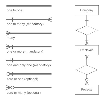
Fig 19: Notation of ER Diagram
● A mapping constraint is a data constraint representing the number of entities to which a relationship set can relate to another entity.
● It is most useful to define relationship sets involving more than two sets of individuals.
● There are four possible mapping cardinalities for the binary relationship set R on an entity set A and B. They are as follows
- One to one (1:1)
- One to many (1:M)
- Many to one (M:1)
- Many to many (M:M)
One to one: As we have seen in the example above, only one instance of an entity is mapped to one instance of another entity. Consider the Department's HOD. Just one HOD in one department exists. That is, the relationship between the HOD agency and the Department is 1:1.
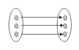
Fig 20: One to one mapping
One to many: As we can guess now, there is one instance of an entity linked to many instances of another entity between one and several relationships. In his department, one manager oversees several employees.
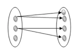
Fig 21: One to many mapping
Many to one: In a one-to-many mapping, an entity in E1 is linked to no more than one entity in E2, whereas an entity in E2 can be linked to any number of entities in E1.
Many to many: This is a relationship where multiple entity instances are linked to multiple entity instances.

Fig 22: Many to many mapping
Key takeaway:
- It is most useful to define relationship sets involving more than two sets of individuals.
- There are four possible mapping cardinalities for the binary relationship.
Keys are the entity's attributes, which define the entity's record uniquely.
Several types of keys exist.
These are listed underneath:
● Candidate key
A candidate key is a key that is simple or composite and special and minimal. It is special since no two rows can have the same value at any time in a table. It is minimal since, in order to achieve uniqueness, every column is required.
● Super key
The Super Key is one or more of the entity's attributes that uniquely define the database record.
● Primary key
The primary key is a candidate key that the database designer chooses to be used as an identification mechanism for the entire set of entities. In a table, it must uniquely classify tuples and not be null.
In the ER model, the primary key is indicated by underlining the attribute.
● To uniquely recognise tuples in a table, the designer selects a candidate key. It must not be empty.
● A key is selected by the database builder to be used by the entire entity collection as an authentication mechanism. This is regarded as the primary key. In the ER model, this key is indicated by underlining the attribute.
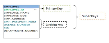
Fig 23: Shows different keys
● Alternate key
Alternate keys are all candidate keys not chosen as the primary key.
● Foreign key
A foreign key (FK) is an attribute in a table that, in another table, references the primary key OR it may be null. The same data type must be used for both international and primary keys.
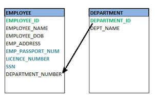
Fig 24: Foreign key
● Secondary key
A secondary key is an attribute used exclusively (can be composite) for retrieval purposes, such as: phone and last name.
● Composite key
A composite key consists of two attributes or more, but it must be minimal.
Key takeaway:
● Keys are the entity's attributes, which define the entity's record uniquely.
● A candidate key is a key that is simple or composite and special and minimal.
● Primary key, uniquely recognised tuples in a table, the designer selects a candidate key. It must not be empty.
● Generalization is similar to a bottom-up strategy in which two or more lower-level entities merge to form a higher-level entity if they share certain attributes.
● In general, an entity of a higher level may combine with entities of a lower level to create a new entity of a higher level.
● The approach to generalization is similar to that of the subclass and superclass systems. The bottom-up method is used in generalization.
● Entities are combined to form a more abstract entity in generalization, i.e., subclasses are combined to form a superclass.
For example, Faculty and Student entities may be combined to form the higher-level entity Individual.
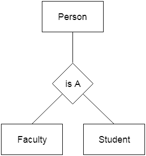
Fig 25: Generalization
Aggregation
The relationship between two entities is considered as a single entity in aggregation. Aggregation is the process of combining relationships with their related entities into a higher level entity.
For example, the Center entity provides the Course entity with the ability to function as a single entity in a relationship with another entity visitor. When a visitor visits a coaching center in the real world, he would never inquire about the Course or the Center alone; instead, he will inquire about both.
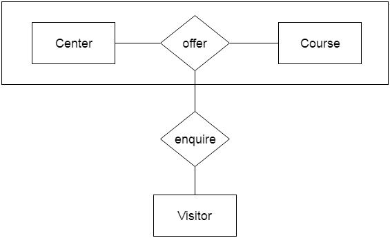
Fig 26: Aggregation
Key takeaway:
- Generalization is similar to a bottom-up strategy in which two or more lower-level entities merge to form a higher-level entity if they share certain attributes.
- Generalization is similar to a bottom-up strategy in which two or more lower-level entities merge to form a higher-level entity if they share certain attributes.
Using notations, the database can be represented, and these notations can be reduced to a set of tables.
Each entity set or relationship set can be represented in tabular form in the database.
The ER diagram is given below:
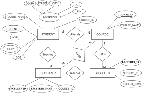
Fig 27: ER diagram
There are some points for converting the ER diagram to the table:
● Entity type becomes a table.
In the given ER diagram, LECTURE, STUDENT, SUBJECT and COURSE forms individual tables.
● All single-valued attributes become a column for the table.
In the STUDENT entity, STUDENT_NAME and STUDENT_ID form the column of STUDENT table. Similarly, COURSE_NAME and COURSE_ID form the column of COURSE table and so on.
● A key attribute of the entity type represented by the primary key.
In the given ER diagram, COURSE_ID, STUDENT_ID, SUBJECT_ID, and LECTURE_ID are the key attributes of the entity.
● The multivalued attribute is represented by a separate table.
A hobby is a multivalued feature inside the student table. Thus, multiple values cannot be expressed in a single column of the STUDENT table. We therefore generate a STUD HOBBY table with the STUDENT ID and HOBBY column names. We create a composite key by using both columns.
● Composite attribute represented by components.
Student address is a composite attribute in the given ER diagram. CITY, PIN, DOOR#, Path, and STATE are included. These attributes will merge as an individual column in the STUDENT table.
● Derived attributes are not considered in the table.
In the STUDENT table, the derived attribute is age. It can be determined by measuring the difference between the present date and the date of birth at any time.
You can convert the ER diagram to tables and columns using these rules and assign the mapping between the tables.
The following is the table structure for the given ER diagram:
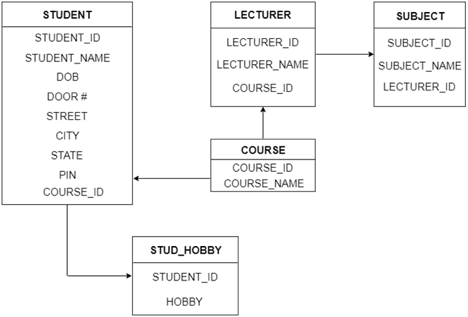
Fig 28: Table structure
Key takeaway:
- Each entity set or relationship set can be represented in tabular form in the database.
- Using notations, the database can be represented, and these notations can be reduced to a set of tables.
The Extended Entity-Relationship Model (EERM) is a more abstract and high-level model that expands the E/R model to include more forms of relationships and attributes, as well as to articulate constraints more clearly. The EE/R model includes all of the concepts found in the E/R model, as well as additional concepts that cover more semantic information.
In addition to ER model concepts EE-R includes −
● Subclasses and Superclasses.
● Specialization and Generalization.
● Category or union type.
● Aggregation.
These concepts are used to create EE-R diagrams.
Key takeaway:
- EER is a high-level data model that integrates the original ER model's extensions. Enhanced ERD models are high-level representations of the specifications and complexities of complex databases.
- Generalization/specialization, association, inheritance, and subclass / superclass are some of the additional definitions.
The number of occurrences in one entity that are correlated with the number of occurrences in another entity is known as the degree of relationship.
There are three types of relationships:
- One-to-one (1:1)
● One occurrence of one entity corresponds to one occurrence of another entity in a one-to-one relationship.
● In reality, a one-to-one partnership is uncommon.
2. One-to-many (1:M)
● One event in one entity corresponds to multiple occurrences in another entity in a one-to-many relationship.
3. Many-to-many (M:N)
● Many occurrences in one entity lead to many occurrences in another entity in a many-to-many relationship.
● The many-to-many relationship, like the one-to-one relationship, is uncommon in nature.
Key takeaway:
- The number of occurrences in one entity that are correlated with the number of occurrences in another entity is known as the degree of relationship.
References:
- Korth, Silbertz, Sudarshan,” Database Concepts”, McGraw Hill
- Date C J, “An Introduction to Database Systems”, Addision Wesley
- Elmasri, Navathe, “Fundamentals of Database Systems”, Addision Wesley
- O’Neil, Databases, Elsevier Pub.
Unit – 1
Introduction
Database
The database is a set of interrelated data used to efficiently retrieve, insert and remove data. It is also used in the form of a table, schema, views, and reports to organise the data, etc.
You can conveniently retrieve, attach, and delete information using the database.
Database management system (DBMS)
A DBMS is a programme that enables database creation, specification and manipulation, allowing users to easily store, process and analyse information.
DBMS provides one with an interface or a tool to conduct different operations, such as building databases, storing data in them, updating data, creating database tables, and much more.
The DBMS also provides databases with privacy and security. In the case of multiple users, it also ensures data consistency.
Some Example of DBMS:
● MySql
● Oracle
● SQL Server
● IBM DB2
Characteristics of DBMS
● Data stored into tables
● Reduced redundancy
● Query language
● Data consistency
● Security
● DBMS support transactions
● Support multiple user and concurrent access
Key takeaway:
- You can conveniently retrieve, attach, and delete information using the database.
- The DBMS provides databases with privacy and security.
- In the case of multiple users, it also ensures data consistency.
Difference between DBMS and file system, are as follows:
DBMS | File System |
A database management system is a collection of data. The user is not allowed to write procedures in a DBMS. | A file system is a data storage system. The user must write the database management procedures in this method. |
A database management system provides an abstract view of data that hides the information. | The data representation and storage of data are detailed in the file system.
|
A crash recovery mechanism is provided by DBMS, which protects the user from device failure. | The file system lacks a crash mechanism, which means that if the system crashes when entering data, the file's content will be lost. |
A good security mechanism is provided by DBMS. | Under the file system, protecting a file is extremely difficult. |
A database management system provides a broad range of advanced techniques for storing and retrieving data. | The file system is incapable of effectively storing and retrieving data. |
Concurrent data access is handled by DBMSs using some kind of locking.
| Concurrent access in the File system causes a number of issues, such as redirecting the file when others delete or update data. |
The architecture of a database management system influences its design. When dealing with a large number of PCs, web servers, database servers, and other networked elements, the same client/server architecture is used.
A client/server architecture is made up of several PCs and a workstation that are all linked by a network.
The design of a database management system is determined by how users link to the database in order to complete their requests.
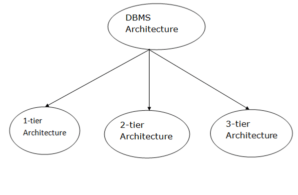
Fig 1: Types of architecture
A single tier or multi-tier database architecture can be seen. However, database design can be divided into two categories: 2-tier architecture and 3-tier architecture.
1-tier Architecture:
The database is directly accessible to the user in this architecture. It means that the user can sit on the DBMS and use it directly. Any modifications made here will be applied directly to the database. It does not provide end users with a useful tool.
For the creation of local applications, a 1-tier architecture is used, in which programmers can interact directly with the database for fast responses.
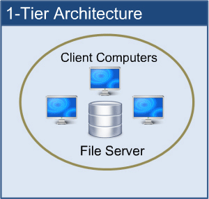
Fig 2: 1-tier architecture
2-tier Architecture:
The 2-tier architecture is similar to the basic client-server architecture. Client-side applications can interact directly with the database on the server side in a two-tier architecture. APIs such as ODBC and JDBC are used for this interaction.
The client-side runs the user interfaces and application programs. The server side is in charge of providing features such as query processing and transaction management. The client-side application creates a link with the server side in order to communicate with the DBMS.
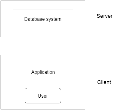
Fig 3: 2-tier architecture
3-tier Architecture:
Between the client and the server is another layer in the 3-tier architecture. The client cannot communicate directly with the server in this architecture. The client-side program communicates with an application server, which in turn communicates with the database system.
Beyond the application server, the end user is unaware of the database's presence. Aside from the submission, the database has no knowledge about any other users.
In the case of a wide web application, the 3-tier architecture is used.
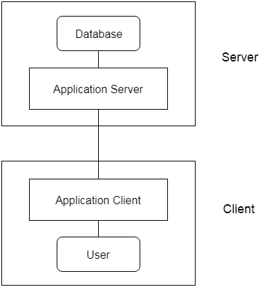
Fig 4: 3-tier architecture
● An instance of the database is the data that is stored in the database at a specific point in time.
● Schema refers to a database's overall configuration.
● A database schema is the database's skeleton structure. It reflects the entire database's logical view.
● Tables, foreign keys, primary keys, views, columns, data types, stored procedures, and other schema objects are included in a schema.
● The visual diagram can be used to describe a database schema. This diagram depicts the database objects and their relationships.
● Database schemas are created by database designers to assist programmers who will be working with the database. Data modeling is the term for the method of creating a database.
Only certain elements of a schema, such as the name of the record type, data type, and constraints, can be shown in a schema diagram. The schema diagram does not allow for the specification of other aspects. The provided figure, for example, does not indicate the data form of each data item or the relationship between the different files.
Actual data in the database is updated on a regular basis. When we add a new grade or a student, for example, the database shifts as seen in the diagram. The database instance refers to the data at a certain point in time.
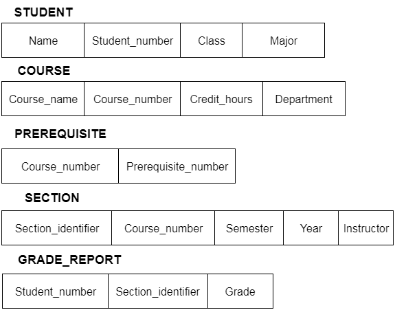
Fig 5: Schema diagram
In addition to users' data, a database system usually includes a lot of data. For instance, to easily locate and retrieve data, it stores information about data, known as metadata. Modifying or modifying a collection of metadata once it is placed in the database is very difficult. But when a DBMS expands, in order to fulfil the users' requirements, it needs to evolve over time. It will become a boring and highly complicated job if the entire data is based.
Metadata itself follows a layered model, such that it does not impact the data at another level when we modify data on one layer. This data is independent, but is mapped to one another.
Types of data independences
● Physical data independence
Physical Data Independence is defined as the ability to make adjustments without affecting the higher-level schemas in the structure of the lowest level of the Database Management System (DBMS). Therefore, the Physical level adjustment does not result in any adjustments to the Conceptual or View levels.
● Logical data independence
Logical Data Independence is defined as the ability to make improvements to the Database Management System (DBMS) middle level structure without affecting the schema or application programmes at the highest level. Changes to the conceptual level should also not result in any changes to the view levels or programmes of the application.
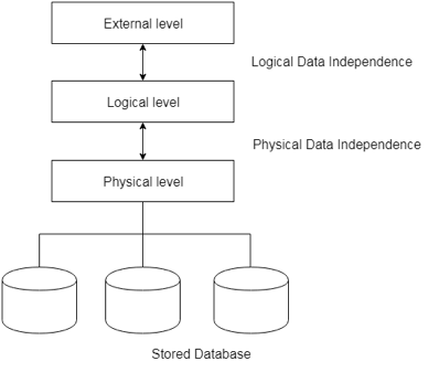
Fig 6: Data independence
Database language:
Users can interact with DBMS using database languages. There are two types of database languages:
1. The Data Definition Language (DDL)
2. The Data Manipulation Language (DML)
Interfaces
● Menu-based interfaces for Web clients or browsing
● Forms-based interfaces
● Graphical user interfaces
● Natural language interfaces
● Speech input and output
● Interfaces for parametric users
● Interfaces for the DBA
Key takeaway:
- The freedom of logical data refers to the ability to alter the conceptual schema without the external schema needing to be modified.
- Independence of physical data can be defined as the ability to alter the internal schema without the conceptual schema having to be modified.
In reality, the DDL or Data Definition Language consists of SQL commands that can be used to define the schema for the database. It basically deals with database schema definitions and is used to construct and change the configuration of database objects in the database.
Some of the commands that fall under DDL are as follows:
● CREATE
● ALTER
● DROP
● TRUNCATE
CREATE
It is used in the database for the development of a new table
Syntax
CREATE TABLE TABLE_NAME (COLUMN_NAME DATA TYPES[,....]);
Example
CREATE TABLE STUDENT(Name VARCHAR2(20), Address VARCHAR2(100), DOB DATE);
ALTER
It is used to modify the database structure. This move may be either to change the characteristics of an existing attribute or to add a new attribute, likely.
Syntax
In order to add a new column to the table:
ALTER TABLE table_name ADD column_name COLUMN-definition;
To change the current table column:
ALTER TABLE MODIFY(COLUMN DEFINITION....);
Example
ALTER TABLE STU_DETAILS ADD(ADDRESS VARCHAR2(20));
ALTER TABLE STU_DETAILS MODIFY (NAME VARCHAR2(20));
Drop
It is used to delete both the structure of the table and the record.
Syntax
DROP TABLE;
Example
DROP TABLE STUDENT;
TRUNCATE
It is used to erase from the table all rows and free up the space containing the table.
Syntax
TRUNCATE TABLE table_name;
Example
TRUNCATE TABLE STUDENT;
Data Manipulation Language (DML)
To change the database, DML commands are used. It is responsible for all forms of database changes.
The DML command is not auto-committed, which means all the changes in the database will not be permanently saved. There may be rollbacks.
Commands under DML
a. INSERT
The INSERT statement is a query from SQL. It is used for the insertion of data into a table row.
Syntax
INSERT INTO TABLE_NAME
(col1, col2, col3,.... Col N)
VALUES (value1, value2, value3, .... ValueN);
Or
INSERT INTO TABLE_NAME
VALUES (value1, value2, value3, .... ValueN);
b. UPDATE
This command is used to update or alter the value of a table column.
Syntax
UPDATE table_name SET [column_name1= value1,...column_nameN = valueN] [WHERE CONDITION]
c. DELETE
It is used to extract a table from one or more rows.
Syntax
DELETE FROM table_name [WHERE condition];
Types of DML: -
a. Procedural: -
It requires a user to specify what data is needed and how to retrieve it from the database. The user instructs the system to perform a sequence of options on the database to compute the desired result.
b. Non-Procedural: -
It requires a user to specify what data is needed without specifying how to get it.
Key takeaway:
- The DDL or Data Definition Language consists of SQL commands that can be used to define the schema for the database.
- To change the database, DML commands are used. It is responsible for all forms of database changes.
- The DML command is not auto-committed, which means all the changes in the database will not be permanently saved.
A system of databases is divided into modules dealing with each of the overall system's responsibilities. A database system's functional components can be narrowly divided into the components of the storage manager and the query processor. The storage manager is essential since a large amount of storage space is usually needed for databases. The query processor is important because it simplifies and promotes access to data by supporting the database system.
It is the responsibility of the database system to convert, at the logical level, changes and queries written in a non-procedural language into an effective sequence of physical level operations.
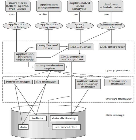
Fig 7: Overall structure of DBMS
The database system is divided into three components: Query Processor, Storage Manager, and Disk Storage
● Query processor
It interprets the requests (queries) received from the end user into instructions through an application programme. Also, the user request that is received from the DML compiler is executed.
The Query Processor comprises the following parts:
● DML compiler
The DML statements are processed into low-level (machine language) instructions so that they can be implemented.
● DDL interpreter
The DDL statements are processed into a table set containing metadata (data about data).
● Query optimization
Typically, a question can be converted into any of a variety of alternative assessment plans that all offer the same outcome. The DML compiler also performs query optimization, which is to say, among the alternatives, it selects the lowest cost evaluation plan.
● Query evaluation engine
That executes the low-level instructions that the DML compiler generates.
● Storage manager
A storage manager is a software module that provides an interface between the low-level data stored in the database and the system-submitted application programmes and queries. Interaction with the file manager is the responsibility of the storage manager. Using the file system, which is typically supported by a conventional operating system, raw data is stored on the disc. The storage manager converts the different DML statements into low-level commands for the file system. It is also the duty of the storage manager to store, retrieve, and update data in the database.
The components for the storage manager include:
● Authorization and integrity manager
This ensures role-based regulation of access, i.e., It checks whether or not the individual is entitled to conduct the requested activity.
When the database is updated, the integrity manager checks the integrity constraints.
● Transaction manager
It manages simultaneous access by executing the operations in a scheduled manner in which the transaction is received. It also ensures that the database stays in a consistent state before and after a transaction has been executed.
● File manager
It manages the space of the file and the data structure used in the database to represent information.
● Buffer manager
The cache memory and data transfer between the secondary storage and the main memory are responsible for this.
● Disk storage
It includes the following elements-
● Data files
It stores the data.
● Data dictionary
It includes details about any database object's structure. It is the information repository that regulates metadata.
● Indices
It provides faster retrieval of data items.
Key takeaway:
- A database system's functional components can be narrowly divided into the components of the storage manager and the query processor.
- A system of databases is divided into modules dealing with each of the overall system's responsibilities.
- The storage manager converts the different DML statements into low-level commands for the file system.
● The Entity-Relationship model (ER model) is a type of entity-relationship model. It's a data model at a high level. The data elements and relationships for a given system are described using this model.
● It creates a database's conceptual architecture. It also creates a very convenient and easy-to-design data view.
● The database structure is depicted as a diagram called an entity-relationship diagram in ER modeling.
Let's say we're creating a database for a school. The student will be an object in this database, with attributes such as address, name, id, age, and so on. There will be a relationship between the address and another entity with attributes such as city, street name, pin code, and so on.
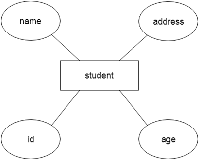
Fig 8: Example of ER
Component of ER model -
The following components are composed of an ER Diagram:
- Entity
- Attributes
- Relationships
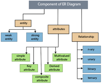
Fig 9: Component of ER model
1.Entity
The object, location, person, or event that stores data in the database may be an entity. In an object-relationship diagram, a rectangle represents an entity.
Examples of an individual include a student, course, boss, employee, patient, etc.

Fig 10: Entity
Entity type:
A list or a set of entities having certain common attributes is an entity type. In a database, a name and a list of attributes define each type of entity.
Entity set:
It is a set (or collection) of entities of the same kind that share attributes or related properties.
For example, it is possible to describe the category of individuals who are lecturers at a university as an entity-set lecturer. Similarly, the collection of students of the organization could represent the community of all university students.
2.Attribute
In an Entity-Relationship Model, an attribute defines an entity's properties or characteristics. It is represented in the ER diagram by an oval or ellipse shape. Each oval shape represents one attribute and is directly linked to the person that is in the shape of the rectangle.
For instance, the attributes defining the Employee form of entity are employee id, employee name, gender, employee age, salary, and mobile no.
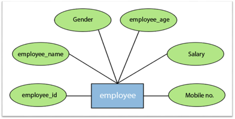
Fig 11: Different attributes of employee
In the ER model, the following categories can be defined by an attribute:
1.Simple attribute:
A simple attribute is called an attribute which contains an atomic value and can not be divided further. The gender and salary of a worker, for instance, is also depicted by an oval.
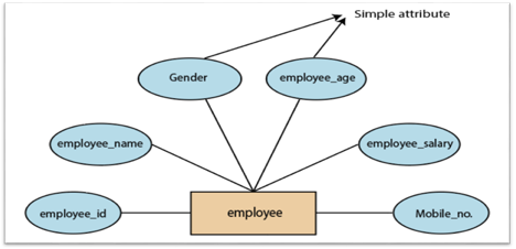
Fig 12: Simple attribute
2. Key attribute:
A key attribute is called an attribute that can uniquely identify an entity in an entity set. It represents a primary key in the ER diagram. In an Entity Relationship diagram, the key attribute is denoted by an oval with an underlying line. For example, for each employee, the employee id would be unique.
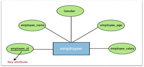
Fig 13: Key attributes
3. Composite attribute:
An attribute that is a combination of two or more basic attributes is called a composite attribute. It is defined by an ellipse in an Entity-Relationship diagram, and that ellipse consists of other ellipses. For example, an employee entity type's name attribute consists of first name, second name, and last name.
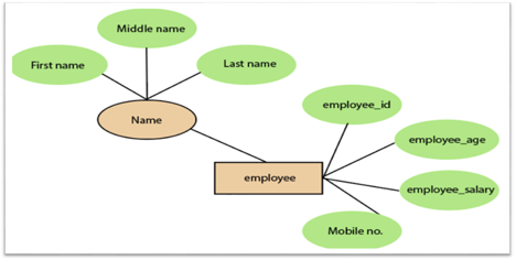
Fig 14: Composite attribute
4.Derived attribute:
A derived attribute is considered an attribute which can be derived from other attributes. In an entity-relationship diagram, a dashed oval shape is used to represent these attributes. Employee age is, for example, a derived attribute since it varies over time and can be derived from another DOB attribute (Date of birth).
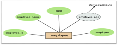
Fig 15: Derived attribute
5.Multivalued attributes:
An attribute which for a given entity contains more than one value. For instance, there may be more than one mobile number and email address for an employee.
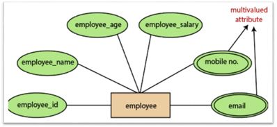
Fig 16: Multivalued attribute
3.Relationship
In the Entity-Relation Model, a relationship is used to define the relationship between two or more entities. In the ER diagram, it is illustrated by a diamond shape.
For example, in college student studies, employees work in a department. Here, the links are 'research in' and 'works in'.
Degree of Relationship
A partnership is called the degree of a relationship in which a variety of different individuals participate.
Degree of relationship can be categorized into the following types:
1. Unary Relationship:
A relationship in which a single group of individuals is involved is referred to as a unary relationship. For instance, in a company, an employee manages or supervises another employee.
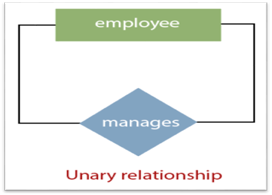
Fig 17: Unary relationship
2. Binary Relationship: When a relationship includes two people, it is considered a binary relationship.
3. Ternary Relationship: When a relationship contains three individual sets, a ternary relationship is called.
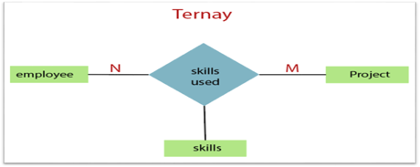
Fig 18: Ternary relationship
4. N-nary Relationship:
If a relationship includes more than three entity sets, an n-ary relationship is named.
Key takeaway:
- The object, location, person, or event that stores data in the database may be an entity.
- In an Entity-Relationship Model, an attribute defines an entity's properties or characteristics.
- Attributes are represented in the ER diagram by an oval or ellipse shape.
- In the Entity-Relation Model, a relationship is used to define the relationship between two or more entities.
The notations can be used to describe a database. Many notations are used to express cardinality in an ER diagram. The following are the notations:
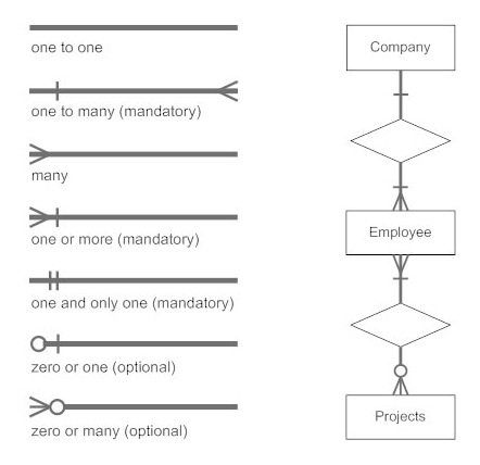
Fig 19: Notation of ER Diagram
● A mapping constraint is a data constraint representing the number of entities to which a relationship set can relate to another entity.
● It is most useful to define relationship sets involving more than two sets of individuals.
● There are four possible mapping cardinalities for the binary relationship set R on an entity set A and B. They are as follows
- One to one (1:1)
- One to many (1:M)
- Many to one (M:1)
- Many to many (M:M)
One to one: As we have seen in the example above, only one instance of an entity is mapped to one instance of another entity. Consider the Department's HOD. Just one HOD in one department exists. That is, the relationship between the HOD agency and the Department is 1:1.
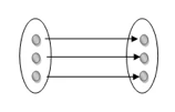
Fig 20: One to one mapping
One to many: As we can guess now, there is one instance of an entity linked to many instances of another entity between one and several relationships. In his department, one manager oversees several employees.
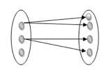
Fig 21: One to many mapping
Many to one: In a one-to-many mapping, an entity in E1 is linked to no more than one entity in E2, whereas an entity in E2 can be linked to any number of entities in E1.
Many to many: This is a relationship where multiple entity instances are linked to multiple entity instances.

Fig 22: Many to many mapping
Key takeaway:
- It is most useful to define relationship sets involving more than two sets of individuals.
- There are four possible mapping cardinalities for the binary relationship.
Keys are the entity's attributes, which define the entity's record uniquely.
Several types of keys exist.
These are listed underneath:
● Candidate key
A candidate key is a key that is simple or composite and special and minimal. It is special since no two rows can have the same value at any time in a table. It is minimal since, in order to achieve uniqueness, every column is required.
● Super key
The Super Key is one or more of the entity's attributes that uniquely define the database record.
● Primary key
The primary key is a candidate key that the database designer chooses to be used as an identification mechanism for the entire set of entities. In a table, it must uniquely classify tuples and not be null.
In the ER model, the primary key is indicated by underlining the attribute.
● To uniquely recognise tuples in a table, the designer selects a candidate key. It must not be empty.
● A key is selected by the database builder to be used by the entire entity collection as an authentication mechanism. This is regarded as the primary key. In the ER model, this key is indicated by underlining the attribute.
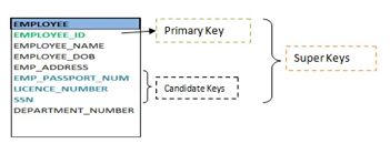
Fig 23: Shows different keys
● Alternate key
Alternate keys are all candidate keys not chosen as the primary key.
● Foreign key
A foreign key (FK) is an attribute in a table that, in another table, references the primary key OR it may be null. The same data type must be used for both international and primary keys.
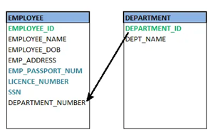
Fig 24: Foreign key
● Secondary key
A secondary key is an attribute used exclusively (can be composite) for retrieval purposes, such as: phone and last name.
● Composite key
A composite key consists of two attributes or more, but it must be minimal.
Key takeaway:
● Keys are the entity's attributes, which define the entity's record uniquely.
● A candidate key is a key that is simple or composite and special and minimal.
● Primary key, uniquely recognised tuples in a table, the designer selects a candidate key. It must not be empty.
● Generalization is similar to a bottom-up strategy in which two or more lower-level entities merge to form a higher-level entity if they share certain attributes.
● In general, an entity of a higher level may combine with entities of a lower level to create a new entity of a higher level.
● The approach to generalization is similar to that of the subclass and superclass systems. The bottom-up method is used in generalization.
● Entities are combined to form a more abstract entity in generalization, i.e., subclasses are combined to form a superclass.
For example, Faculty and Student entities may be combined to form the higher-level entity Individual.
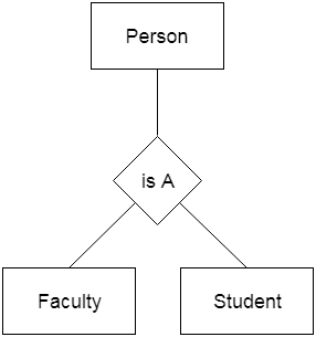
Fig 25: Generalization
Aggregation
The relationship between two entities is considered as a single entity in aggregation. Aggregation is the process of combining relationships with their related entities into a higher level entity.
For example, the Center entity provides the Course entity with the ability to function as a single entity in a relationship with another entity visitor. When a visitor visits a coaching center in the real world, he would never inquire about the Course or the Center alone; instead, he will inquire about both.
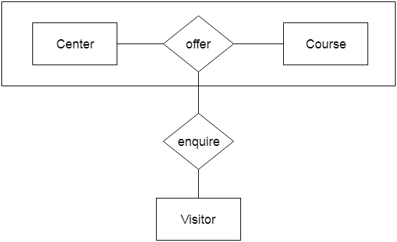
Fig 26: Aggregation
Key takeaway:
- Generalization is similar to a bottom-up strategy in which two or more lower-level entities merge to form a higher-level entity if they share certain attributes.
- Generalization is similar to a bottom-up strategy in which two or more lower-level entities merge to form a higher-level entity if they share certain attributes.
Using notations, the database can be represented, and these notations can be reduced to a set of tables.
Each entity set or relationship set can be represented in tabular form in the database.
The ER diagram is given below:
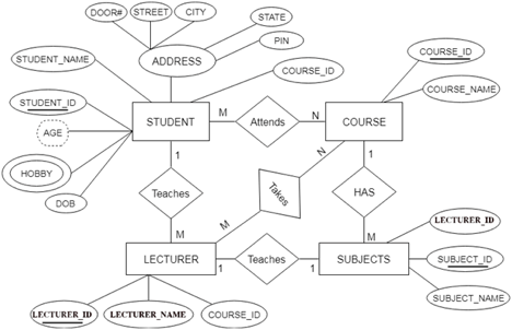
Fig 27: ER diagram
There are some points for converting the ER diagram to the table:
● Entity type becomes a table.
In the given ER diagram, LECTURE, STUDENT, SUBJECT and COURSE forms individual tables.
● All single-valued attributes become a column for the table.
In the STUDENT entity, STUDENT_NAME and STUDENT_ID form the column of STUDENT table. Similarly, COURSE_NAME and COURSE_ID form the column of COURSE table and so on.
● A key attribute of the entity type represented by the primary key.
In the given ER diagram, COURSE_ID, STUDENT_ID, SUBJECT_ID, and LECTURE_ID are the key attributes of the entity.
● The multivalued attribute is represented by a separate table.
A hobby is a multivalued feature inside the student table. Thus, multiple values cannot be expressed in a single column of the STUDENT table. We therefore generate a STUD HOBBY table with the STUDENT ID and HOBBY column names. We create a composite key by using both columns.
● Composite attribute represented by components.
Student address is a composite attribute in the given ER diagram. CITY, PIN, DOOR#, Path, and STATE are included. These attributes will merge as an individual column in the STUDENT table.
● Derived attributes are not considered in the table.
In the STUDENT table, the derived attribute is age. It can be determined by measuring the difference between the present date and the date of birth at any time.
You can convert the ER diagram to tables and columns using these rules and assign the mapping between the tables.
The following is the table structure for the given ER diagram:
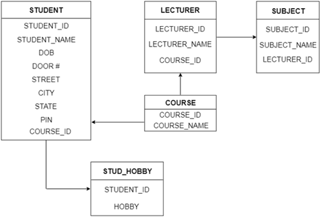
Fig 28: Table structure
Key takeaway:
- Each entity set or relationship set can be represented in tabular form in the database.
- Using notations, the database can be represented, and these notations can be reduced to a set of tables.
The Extended Entity-Relationship Model (EERM) is a more abstract and high-level model that expands the E/R model to include more forms of relationships and attributes, as well as to articulate constraints more clearly. The EE/R model includes all of the concepts found in the E/R model, as well as additional concepts that cover more semantic information.
In addition to ER model concepts EE-R includes −
● Subclasses and Superclasses.
● Specialization and Generalization.
● Category or union type.
● Aggregation.
These concepts are used to create EE-R diagrams.
Key takeaway:
- EER is a high-level data model that integrates the original ER model's extensions. Enhanced ERD models are high-level representations of the specifications and complexities of complex databases.
- Generalization/specialization, association, inheritance, and subclass / superclass are some of the additional definitions.
The number of occurrences in one entity that are correlated with the number of occurrences in another entity is known as the degree of relationship.
There are three types of relationships:
- One-to-one (1:1)
● One occurrence of one entity corresponds to one occurrence of another entity in a one-to-one relationship.
● In reality, a one-to-one partnership is uncommon.
2. One-to-many (1:M)
● One event in one entity corresponds to multiple occurrences in another entity in a one-to-many relationship.
3. Many-to-many (M:N)
● Many occurrences in one entity lead to many occurrences in another entity in a many-to-many relationship.
● The many-to-many relationship, like the one-to-one relationship, is uncommon in nature.
Key takeaway:
- The number of occurrences in one entity that are correlated with the number of occurrences in another entity is known as the degree of relationship.
References:
- Korth, Silbertz, Sudarshan,” Database Concepts”, McGraw Hill
- Date C J, “An Introduction to Database Systems”, Addision Wesley
- Elmasri, Navathe, “Fundamentals of Database Systems”, Addision Wesley
- O’Neil, Databases, Elsevier Pub.
Unit – 1
Introduction
Database
The database is a set of interrelated data used to efficiently retrieve, insert and remove data. It is also used in the form of a table, schema, views, and reports to organise the data, etc.
You can conveniently retrieve, attach, and delete information using the database.
Database management system (DBMS)
A DBMS is a programme that enables database creation, specification and manipulation, allowing users to easily store, process and analyse information.
DBMS provides one with an interface or a tool to conduct different operations, such as building databases, storing data in them, updating data, creating database tables, and much more.
The DBMS also provides databases with privacy and security. In the case of multiple users, it also ensures data consistency.
Some Example of DBMS:
● MySql
● Oracle
● SQL Server
● IBM DB2
Characteristics of DBMS
● Data stored into tables
● Reduced redundancy
● Query language
● Data consistency
● Security
● DBMS support transactions
● Support multiple user and concurrent access
Key takeaway:
- You can conveniently retrieve, attach, and delete information using the database.
- The DBMS provides databases with privacy and security.
- In the case of multiple users, it also ensures data consistency.
Difference between DBMS and file system, are as follows:
DBMS | File System |
A database management system is a collection of data. The user is not allowed to write procedures in a DBMS. | A file system is a data storage system. The user must write the database management procedures in this method. |
A database management system provides an abstract view of data that hides the information. | The data representation and storage of data are detailed in the file system.
|
A crash recovery mechanism is provided by DBMS, which protects the user from device failure. | The file system lacks a crash mechanism, which means that if the system crashes when entering data, the file's content will be lost. |
A good security mechanism is provided by DBMS. | Under the file system, protecting a file is extremely difficult. |
A database management system provides a broad range of advanced techniques for storing and retrieving data. | The file system is incapable of effectively storing and retrieving data. |
Concurrent data access is handled by DBMSs using some kind of locking.
| Concurrent access in the File system causes a number of issues, such as redirecting the file when others delete or update data. |
The architecture of a database management system influences its design. When dealing with a large number of PCs, web servers, database servers, and other networked elements, the same client/server architecture is used.
A client/server architecture is made up of several PCs and a workstation that are all linked by a network.
The design of a database management system is determined by how users link to the database in order to complete their requests.
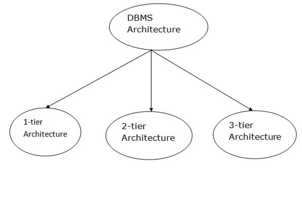
Fig 1: Types of architecture
A single tier or multi-tier database architecture can be seen. However, database design can be divided into two categories: 2-tier architecture and 3-tier architecture.
1-tier Architecture:
The database is directly accessible to the user in this architecture. It means that the user can sit on the DBMS and use it directly. Any modifications made here will be applied directly to the database. It does not provide end users with a useful tool.
For the creation of local applications, a 1-tier architecture is used, in which programmers can interact directly with the database for fast responses.
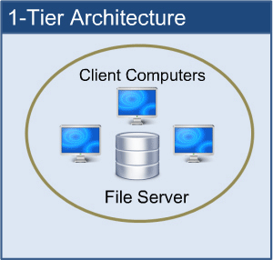
Fig 2: 1-tier architecture
2-tier Architecture:
The 2-tier architecture is similar to the basic client-server architecture. Client-side applications can interact directly with the database on the server side in a two-tier architecture. APIs such as ODBC and JDBC are used for this interaction.
The client-side runs the user interfaces and application programs. The server side is in charge of providing features such as query processing and transaction management. The client-side application creates a link with the server side in order to communicate with the DBMS.
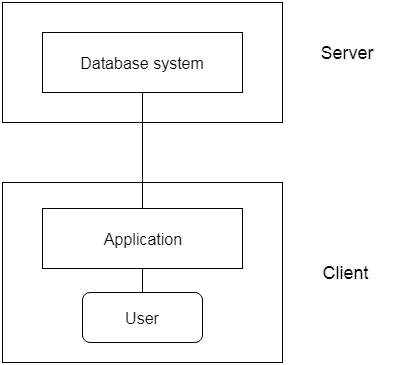
Fig 3: 2-tier architecture
3-tier Architecture:
Between the client and the server is another layer in the 3-tier architecture. The client cannot communicate directly with the server in this architecture. The client-side program communicates with an application server, which in turn communicates with the database system.
Beyond the application server, the end user is unaware of the database's presence. Aside from the submission, the database has no knowledge about any other users.
In the case of a wide web application, the 3-tier architecture is used.
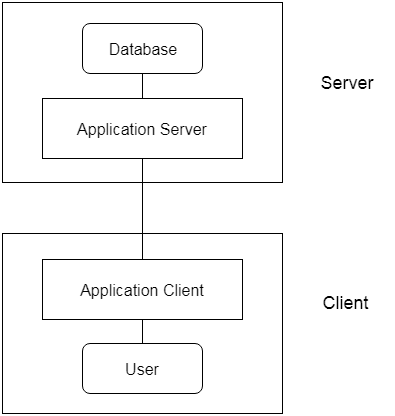
Fig 4: 3-tier architecture
● An instance of the database is the data that is stored in the database at a specific point in time.
● Schema refers to a database's overall configuration.
● A database schema is the database's skeleton structure. It reflects the entire database's logical view.
● Tables, foreign keys, primary keys, views, columns, data types, stored procedures, and other schema objects are included in a schema.
● The visual diagram can be used to describe a database schema. This diagram depicts the database objects and their relationships.
● Database schemas are created by database designers to assist programmers who will be working with the database. Data modeling is the term for the method of creating a database.
Only certain elements of a schema, such as the name of the record type, data type, and constraints, can be shown in a schema diagram. The schema diagram does not allow for the specification of other aspects. The provided figure, for example, does not indicate the data form of each data item or the relationship between the different files.
Actual data in the database is updated on a regular basis. When we add a new grade or a student, for example, the database shifts as seen in the diagram. The database instance refers to the data at a certain point in time.
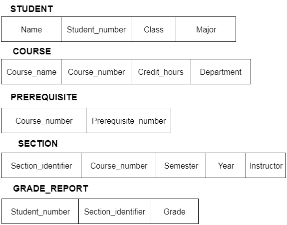
Fig 5: Schema diagram
In addition to users' data, a database system usually includes a lot of data. For instance, to easily locate and retrieve data, it stores information about data, known as metadata. Modifying or modifying a collection of metadata once it is placed in the database is very difficult. But when a DBMS expands, in order to fulfil the users' requirements, it needs to evolve over time. It will become a boring and highly complicated job if the entire data is based.
Metadata itself follows a layered model, such that it does not impact the data at another level when we modify data on one layer. This data is independent, but is mapped to one another.
Types of data independences
● Physical data independence
Physical Data Independence is defined as the ability to make adjustments without affecting the higher-level schemas in the structure of the lowest level of the Database Management System (DBMS). Therefore, the Physical level adjustment does not result in any adjustments to the Conceptual or View levels.
● Logical data independence
Logical Data Independence is defined as the ability to make improvements to the Database Management System (DBMS) middle level structure without affecting the schema or application programmes at the highest level. Changes to the conceptual level should also not result in any changes to the view levels or programmes of the application.
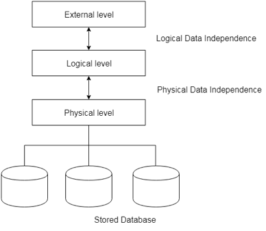
Fig 6: Data independence
Database language:
Users can interact with DBMS using database languages. There are two types of database languages:
1. The Data Definition Language (DDL)
2. The Data Manipulation Language (DML)
Interfaces
● Menu-based interfaces for Web clients or browsing
● Forms-based interfaces
● Graphical user interfaces
● Natural language interfaces
● Speech input and output
● Interfaces for parametric users
● Interfaces for the DBA
Key takeaway:
- The freedom of logical data refers to the ability to alter the conceptual schema without the external schema needing to be modified.
- Independence of physical data can be defined as the ability to alter the internal schema without the conceptual schema having to be modified.
In reality, the DDL or Data Definition Language consists of SQL commands that can be used to define the schema for the database. It basically deals with database schema definitions and is used to construct and change the configuration of database objects in the database.
Some of the commands that fall under DDL are as follows:
● CREATE
● ALTER
● DROP
● TRUNCATE
CREATE
It is used in the database for the development of a new table
Syntax
CREATE TABLE TABLE_NAME (COLUMN_NAME DATA TYPES[,....]);
Example
CREATE TABLE STUDENT(Name VARCHAR2(20), Address VARCHAR2(100), DOB DATE);
ALTER
It is used to modify the database structure. This move may be either to change the characteristics of an existing attribute or to add a new attribute, likely.
Syntax
In order to add a new column to the table:
ALTER TABLE table_name ADD column_name COLUMN-definition;
To change the current table column:
ALTER TABLE MODIFY(COLUMN DEFINITION....);
Example
ALTER TABLE STU_DETAILS ADD(ADDRESS VARCHAR2(20));
ALTER TABLE STU_DETAILS MODIFY (NAME VARCHAR2(20));
Drop
It is used to delete both the structure of the table and the record.
Syntax
DROP TABLE;
Example
DROP TABLE STUDENT;
TRUNCATE
It is used to erase from the table all rows and free up the space containing the table.
Syntax
TRUNCATE TABLE table_name;
Example
TRUNCATE TABLE STUDENT;
Data Manipulation Language (DML)
To change the database, DML commands are used. It is responsible for all forms of database changes.
The DML command is not auto-committed, which means all the changes in the database will not be permanently saved. There may be rollbacks.
Commands under DML
a. INSERT
The INSERT statement is a query from SQL. It is used for the insertion of data into a table row.
Syntax
INSERT INTO TABLE_NAME
(col1, col2, col3,.... Col N)
VALUES (value1, value2, value3, .... ValueN);
Or
INSERT INTO TABLE_NAME
VALUES (value1, value2, value3, .... ValueN);
b. UPDATE
This command is used to update or alter the value of a table column.
Syntax
UPDATE table_name SET [column_name1= value1,...column_nameN = valueN] [WHERE CONDITION]
c. DELETE
It is used to extract a table from one or more rows.
Syntax
DELETE FROM table_name [WHERE condition];
Types of DML: -
a. Procedural: -
It requires a user to specify what data is needed and how to retrieve it from the database. The user instructs the system to perform a sequence of options on the database to compute the desired result.
b. Non-Procedural: -
It requires a user to specify what data is needed without specifying how to get it.
Key takeaway:
- The DDL or Data Definition Language consists of SQL commands that can be used to define the schema for the database.
- To change the database, DML commands are used. It is responsible for all forms of database changes.
- The DML command is not auto-committed, which means all the changes in the database will not be permanently saved.
A system of databases is divided into modules dealing with each of the overall system's responsibilities. A database system's functional components can be narrowly divided into the components of the storage manager and the query processor. The storage manager is essential since a large amount of storage space is usually needed for databases. The query processor is important because it simplifies and promotes access to data by supporting the database system.
It is the responsibility of the database system to convert, at the logical level, changes and queries written in a non-procedural language into an effective sequence of physical level operations.
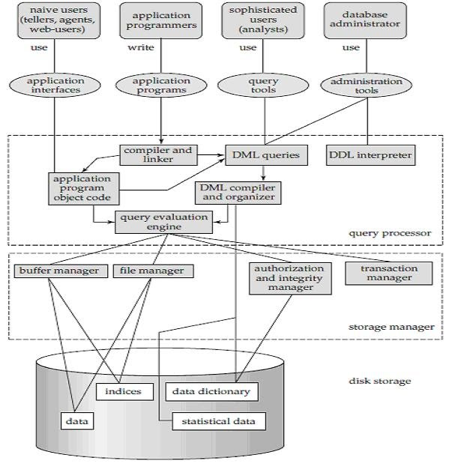
Fig 7: Overall structure of DBMS
The database system is divided into three components: Query Processor, Storage Manager, and Disk Storage
● Query processor
It interprets the requests (queries) received from the end user into instructions through an application programme. Also, the user request that is received from the DML compiler is executed.
The Query Processor comprises the following parts:
● DML compiler
The DML statements are processed into low-level (machine language) instructions so that they can be implemented.
● DDL interpreter
The DDL statements are processed into a table set containing metadata (data about data).
● Query optimization
Typically, a question can be converted into any of a variety of alternative assessment plans that all offer the same outcome. The DML compiler also performs query optimization, which is to say, among the alternatives, it selects the lowest cost evaluation plan.
● Query evaluation engine
That executes the low-level instructions that the DML compiler generates.
● Storage manager
A storage manager is a software module that provides an interface between the low-level data stored in the database and the system-submitted application programmes and queries. Interaction with the file manager is the responsibility of the storage manager. Using the file system, which is typically supported by a conventional operating system, raw data is stored on the disc. The storage manager converts the different DML statements into low-level commands for the file system. It is also the duty of the storage manager to store, retrieve, and update data in the database.
The components for the storage manager include:
● Authorization and integrity manager
This ensures role-based regulation of access, i.e., It checks whether or not the individual is entitled to conduct the requested activity.
When the database is updated, the integrity manager checks the integrity constraints.
● Transaction manager
It manages simultaneous access by executing the operations in a scheduled manner in which the transaction is received. It also ensures that the database stays in a consistent state before and after a transaction has been executed.
● File manager
It manages the space of the file and the data structure used in the database to represent information.
● Buffer manager
The cache memory and data transfer between the secondary storage and the main memory are responsible for this.
● Disk storage
It includes the following elements-
● Data files
It stores the data.
● Data dictionary
It includes details about any database object's structure. It is the information repository that regulates metadata.
● Indices
It provides faster retrieval of data items.
Key takeaway:
- A database system's functional components can be narrowly divided into the components of the storage manager and the query processor.
- A system of databases is divided into modules dealing with each of the overall system's responsibilities.
- The storage manager converts the different DML statements into low-level commands for the file system.
● The Entity-Relationship model (ER model) is a type of entity-relationship model. It's a data model at a high level. The data elements and relationships for a given system are described using this model.
● It creates a database's conceptual architecture. It also creates a very convenient and easy-to-design data view.
● The database structure is depicted as a diagram called an entity-relationship diagram in ER modeling.
Let's say we're creating a database for a school. The student will be an object in this database, with attributes such as address, name, id, age, and so on. There will be a relationship between the address and another entity with attributes such as city, street name, pin code, and so on.
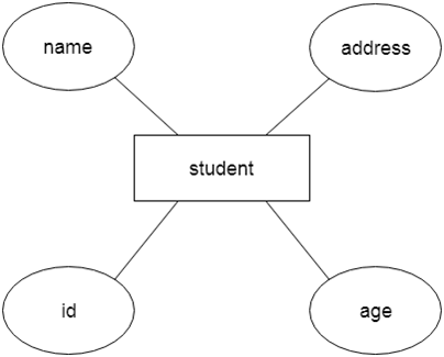
Fig 8: Example of ER
Component of ER model -
The following components are composed of an ER Diagram:
- Entity
- Attributes
- Relationships
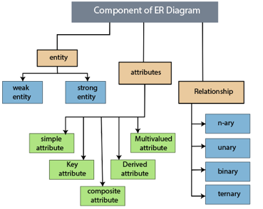
Fig 9: Component of ER model
1.Entity
The object, location, person, or event that stores data in the database may be an entity. In an object-relationship diagram, a rectangle represents an entity.
Examples of an individual include a student, course, boss, employee, patient, etc.

Fig 10: Entity
Entity type:
A list or a set of entities having certain common attributes is an entity type. In a database, a name and a list of attributes define each type of entity.
Entity set:
It is a set (or collection) of entities of the same kind that share attributes or related properties.
For example, it is possible to describe the category of individuals who are lecturers at a university as an entity-set lecturer. Similarly, the collection of students of the organization could represent the community of all university students.
2.Attribute
In an Entity-Relationship Model, an attribute defines an entity's properties or characteristics. It is represented in the ER diagram by an oval or ellipse shape. Each oval shape represents one attribute and is directly linked to the person that is in the shape of the rectangle.
For instance, the attributes defining the Employee form of entity are employee id, employee name, gender, employee age, salary, and mobile no.
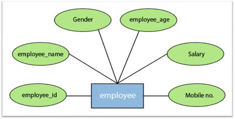
Fig 11: Different attributes of employee
In the ER model, the following categories can be defined by an attribute:
1.Simple attribute:
A simple attribute is called an attribute which contains an atomic value and can not be divided further. The gender and salary of a worker, for instance, is also depicted by an oval.
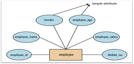
Fig 12: Simple attribute
2. Key attribute:
A key attribute is called an attribute that can uniquely identify an entity in an entity set. It represents a primary key in the ER diagram. In an Entity Relationship diagram, the key attribute is denoted by an oval with an underlying line. For example, for each employee, the employee id would be unique.
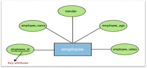
Fig 13: Key attributes
3. Composite attribute:
An attribute that is a combination of two or more basic attributes is called a composite attribute. It is defined by an ellipse in an Entity-Relationship diagram, and that ellipse consists of other ellipses. For example, an employee entity type's name attribute consists of first name, second name, and last name.
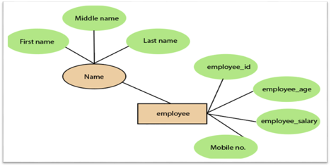
Fig 14: Composite attribute
4.Derived attribute:
A derived attribute is considered an attribute which can be derived from other attributes. In an entity-relationship diagram, a dashed oval shape is used to represent these attributes. Employee age is, for example, a derived attribute since it varies over time and can be derived from another DOB attribute (Date of birth).
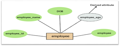
Fig 15: Derived attribute
5.Multivalued attributes:
An attribute which for a given entity contains more than one value. For instance, there may be more than one mobile number and email address for an employee.
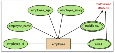
Fig 16: Multivalued attribute
3.Relationship
In the Entity-Relation Model, a relationship is used to define the relationship between two or more entities. In the ER diagram, it is illustrated by a diamond shape.
For example, in college student studies, employees work in a department. Here, the links are 'research in' and 'works in'.
Degree of Relationship
A partnership is called the degree of a relationship in which a variety of different individuals participate.
Degree of relationship can be categorized into the following types:
1. Unary Relationship:
A relationship in which a single group of individuals is involved is referred to as a unary relationship. For instance, in a company, an employee manages or supervises another employee.
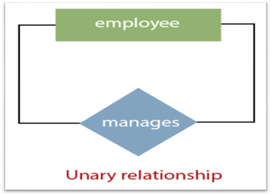
Fig 17: Unary relationship
2. Binary Relationship: When a relationship includes two people, it is considered a binary relationship.
3. Ternary Relationship: When a relationship contains three individual sets, a ternary relationship is called.
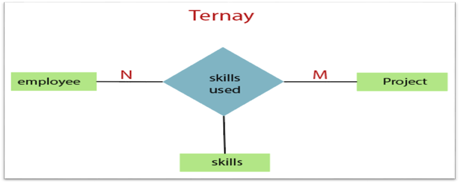
Fig 18: Ternary relationship
4. N-nary Relationship:
If a relationship includes more than three entity sets, an n-ary relationship is named.
Key takeaway:
- The object, location, person, or event that stores data in the database may be an entity.
- In an Entity-Relationship Model, an attribute defines an entity's properties or characteristics.
- Attributes are represented in the ER diagram by an oval or ellipse shape.
- In the Entity-Relation Model, a relationship is used to define the relationship between two or more entities.
The notations can be used to describe a database. Many notations are used to express cardinality in an ER diagram. The following are the notations:
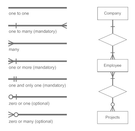
Fig 19: Notation of ER Diagram
● A mapping constraint is a data constraint representing the number of entities to which a relationship set can relate to another entity.
● It is most useful to define relationship sets involving more than two sets of individuals.
● There are four possible mapping cardinalities for the binary relationship set R on an entity set A and B. They are as follows
- One to one (1:1)
- One to many (1:M)
- Many to one (M:1)
- Many to many (M:M)
One to one: As we have seen in the example above, only one instance of an entity is mapped to one instance of another entity. Consider the Department's HOD. Just one HOD in one department exists. That is, the relationship between the HOD agency and the Department is 1:1.
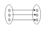
Fig 20: One to one mapping
One to many: As we can guess now, there is one instance of an entity linked to many instances of another entity between one and several relationships. In his department, one manager oversees several employees.
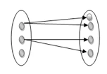
Fig 21: One to many mapping
Many to one: In a one-to-many mapping, an entity in E1 is linked to no more than one entity in E2, whereas an entity in E2 can be linked to any number of entities in E1.
Many to many: This is a relationship where multiple entity instances are linked to multiple entity instances.

Fig 22: Many to many mapping
Key takeaway:
- It is most useful to define relationship sets involving more than two sets of individuals.
- There are four possible mapping cardinalities for the binary relationship.
Unit – 1
Introduction
Database
The database is a set of interrelated data used to efficiently retrieve, insert and remove data. It is also used in the form of a table, schema, views, and reports to organise the data, etc.
You can conveniently retrieve, attach, and delete information using the database.
Database management system (DBMS)
A DBMS is a programme that enables database creation, specification and manipulation, allowing users to easily store, process and analyse information.
DBMS provides one with an interface or a tool to conduct different operations, such as building databases, storing data in them, updating data, creating database tables, and much more.
The DBMS also provides databases with privacy and security. In the case of multiple users, it also ensures data consistency.
Some Example of DBMS:
● MySql
● Oracle
● SQL Server
● IBM DB2
Characteristics of DBMS
● Data stored into tables
● Reduced redundancy
● Query language
● Data consistency
● Security
● DBMS support transactions
● Support multiple user and concurrent access
Key takeaway:
- You can conveniently retrieve, attach, and delete information using the database.
- The DBMS provides databases with privacy and security.
- In the case of multiple users, it also ensures data consistency.
Difference between DBMS and file system, are as follows:
DBMS | File System |
A database management system is a collection of data. The user is not allowed to write procedures in a DBMS. | A file system is a data storage system. The user must write the database management procedures in this method. |
A database management system provides an abstract view of data that hides the information. | The data representation and storage of data are detailed in the file system.
|
A crash recovery mechanism is provided by DBMS, which protects the user from device failure. | The file system lacks a crash mechanism, which means that if the system crashes when entering data, the file's content will be lost. |
A good security mechanism is provided by DBMS. | Under the file system, protecting a file is extremely difficult. |
A database management system provides a broad range of advanced techniques for storing and retrieving data. | The file system is incapable of effectively storing and retrieving data. |
Concurrent data access is handled by DBMSs using some kind of locking.
| Concurrent access in the File system causes a number of issues, such as redirecting the file when others delete or update data. |
The architecture of a database management system influences its design. When dealing with a large number of PCs, web servers, database servers, and other networked elements, the same client/server architecture is used.
A client/server architecture is made up of several PCs and a workstation that are all linked by a network.
The design of a database management system is determined by how users link to the database in order to complete their requests.
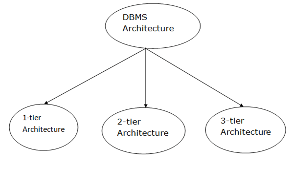
Fig 1: Types of architecture
A single tier or multi-tier database architecture can be seen. However, database design can be divided into two categories: 2-tier architecture and 3-tier architecture.
1-tier Architecture:
The database is directly accessible to the user in this architecture. It means that the user can sit on the DBMS and use it directly. Any modifications made here will be applied directly to the database. It does not provide end users with a useful tool.
For the creation of local applications, a 1-tier architecture is used, in which programmers can interact directly with the database for fast responses.
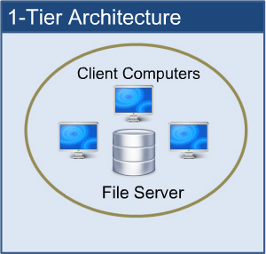
Fig 2: 1-tier architecture
2-tier Architecture:
The 2-tier architecture is similar to the basic client-server architecture. Client-side applications can interact directly with the database on the server side in a two-tier architecture. APIs such as ODBC and JDBC are used for this interaction.
The client-side runs the user interfaces and application programs. The server side is in charge of providing features such as query processing and transaction management. The client-side application creates a link with the server side in order to communicate with the DBMS.
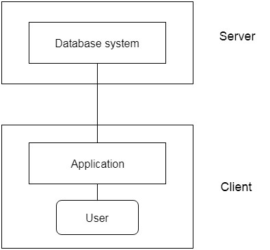
Fig 3: 2-tier architecture
3-tier Architecture:
Between the client and the server is another layer in the 3-tier architecture. The client cannot communicate directly with the server in this architecture. The client-side program communicates with an application server, which in turn communicates with the database system.
Beyond the application server, the end user is unaware of the database's presence. Aside from the submission, the database has no knowledge about any other users.
In the case of a wide web application, the 3-tier architecture is used.
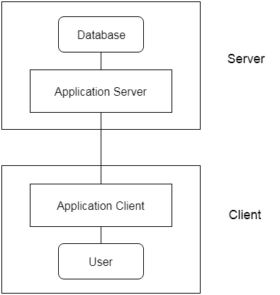
Fig 4: 3-tier architecture
● An instance of the database is the data that is stored in the database at a specific point in time.
● Schema refers to a database's overall configuration.
● A database schema is the database's skeleton structure. It reflects the entire database's logical view.
● Tables, foreign keys, primary keys, views, columns, data types, stored procedures, and other schema objects are included in a schema.
● The visual diagram can be used to describe a database schema. This diagram depicts the database objects and their relationships.
● Database schemas are created by database designers to assist programmers who will be working with the database. Data modeling is the term for the method of creating a database.
Only certain elements of a schema, such as the name of the record type, data type, and constraints, can be shown in a schema diagram. The schema diagram does not allow for the specification of other aspects. The provided figure, for example, does not indicate the data form of each data item or the relationship between the different files.
Actual data in the database is updated on a regular basis. When we add a new grade or a student, for example, the database shifts as seen in the diagram. The database instance refers to the data at a certain point in time.
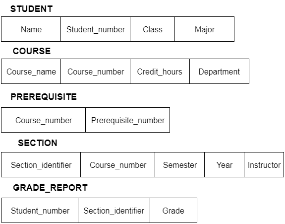
Fig 5: Schema diagram
In addition to users' data, a database system usually includes a lot of data. For instance, to easily locate and retrieve data, it stores information about data, known as metadata. Modifying or modifying a collection of metadata once it is placed in the database is very difficult. But when a DBMS expands, in order to fulfil the users' requirements, it needs to evolve over time. It will become a boring and highly complicated job if the entire data is based.
Metadata itself follows a layered model, such that it does not impact the data at another level when we modify data on one layer. This data is independent, but is mapped to one another.
Types of data independences
● Physical data independence
Physical Data Independence is defined as the ability to make adjustments without affecting the higher-level schemas in the structure of the lowest level of the Database Management System (DBMS). Therefore, the Physical level adjustment does not result in any adjustments to the Conceptual or View levels.
● Logical data independence
Logical Data Independence is defined as the ability to make improvements to the Database Management System (DBMS) middle level structure without affecting the schema or application programmes at the highest level. Changes to the conceptual level should also not result in any changes to the view levels or programmes of the application.
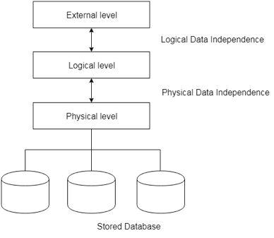
Fig 6: Data independence
Database language:
Users can interact with DBMS using database languages. There are two types of database languages:
1. The Data Definition Language (DDL)
2. The Data Manipulation Language (DML)
Interfaces
● Menu-based interfaces for Web clients or browsing
● Forms-based interfaces
● Graphical user interfaces
● Natural language interfaces
● Speech input and output
● Interfaces for parametric users
● Interfaces for the DBA
Key takeaway:
- The freedom of logical data refers to the ability to alter the conceptual schema without the external schema needing to be modified.
- Independence of physical data can be defined as the ability to alter the internal schema without the conceptual schema having to be modified.
In reality, the DDL or Data Definition Language consists of SQL commands that can be used to define the schema for the database. It basically deals with database schema definitions and is used to construct and change the configuration of database objects in the database.
Some of the commands that fall under DDL are as follows:
● CREATE
● ALTER
● DROP
● TRUNCATE
CREATE
It is used in the database for the development of a new table
Syntax
CREATE TABLE TABLE_NAME (COLUMN_NAME DATA TYPES[,....]);
Example
CREATE TABLE STUDENT(Name VARCHAR2(20), Address VARCHAR2(100), DOB DATE);
ALTER
It is used to modify the database structure. This move may be either to change the characteristics of an existing attribute or to add a new attribute, likely.
Syntax
In order to add a new column to the table:
ALTER TABLE table_name ADD column_name COLUMN-definition;
To change the current table column:
ALTER TABLE MODIFY(COLUMN DEFINITION....);
Example
ALTER TABLE STU_DETAILS ADD(ADDRESS VARCHAR2(20));
ALTER TABLE STU_DETAILS MODIFY (NAME VARCHAR2(20));
Drop
It is used to delete both the structure of the table and the record.
Syntax
DROP TABLE;
Example
DROP TABLE STUDENT;
TRUNCATE
It is used to erase from the table all rows and free up the space containing the table.
Syntax
TRUNCATE TABLE table_name;
Example
TRUNCATE TABLE STUDENT;
Data Manipulation Language (DML)
To change the database, DML commands are used. It is responsible for all forms of database changes.
The DML command is not auto-committed, which means all the changes in the database will not be permanently saved. There may be rollbacks.
Commands under DML
a. INSERT
The INSERT statement is a query from SQL. It is used for the insertion of data into a table row.
Syntax
INSERT INTO TABLE_NAME
(col1, col2, col3,.... Col N)
VALUES (value1, value2, value3, .... ValueN);
Or
INSERT INTO TABLE_NAME
VALUES (value1, value2, value3, .... ValueN);
b. UPDATE
This command is used to update or alter the value of a table column.
Syntax
UPDATE table_name SET [column_name1= value1,...column_nameN = valueN] [WHERE CONDITION]
c. DELETE
It is used to extract a table from one or more rows.
Syntax
DELETE FROM table_name [WHERE condition];
Types of DML: -
a. Procedural: -
It requires a user to specify what data is needed and how to retrieve it from the database. The user instructs the system to perform a sequence of options on the database to compute the desired result.
b. Non-Procedural: -
It requires a user to specify what data is needed without specifying how to get it.
Key takeaway:
- The DDL or Data Definition Language consists of SQL commands that can be used to define the schema for the database.
- To change the database, DML commands are used. It is responsible for all forms of database changes.
- The DML command is not auto-committed, which means all the changes in the database will not be permanently saved.
A system of databases is divided into modules dealing with each of the overall system's responsibilities. A database system's functional components can be narrowly divided into the components of the storage manager and the query processor. The storage manager is essential since a large amount of storage space is usually needed for databases. The query processor is important because it simplifies and promotes access to data by supporting the database system.
It is the responsibility of the database system to convert, at the logical level, changes and queries written in a non-procedural language into an effective sequence of physical level operations.
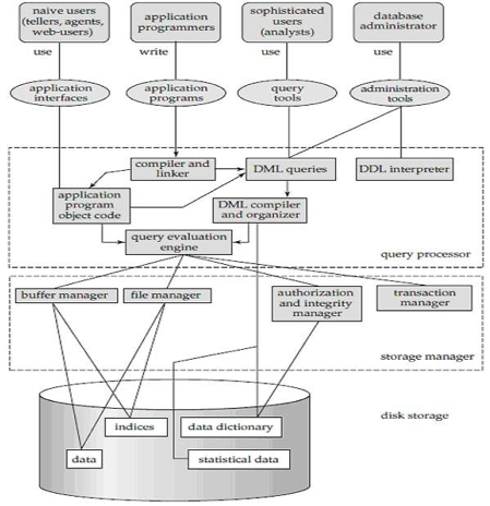
Fig 7: Overall structure of DBMS
The database system is divided into three components: Query Processor, Storage Manager, and Disk Storage
● Query processor
It interprets the requests (queries) received from the end user into instructions through an application programme. Also, the user request that is received from the DML compiler is executed.
The Query Processor comprises the following parts:
● DML compiler
The DML statements are processed into low-level (machine language) instructions so that they can be implemented.
● DDL interpreter
The DDL statements are processed into a table set containing metadata (data about data).
● Query optimization
Typically, a question can be converted into any of a variety of alternative assessment plans that all offer the same outcome. The DML compiler also performs query optimization, which is to say, among the alternatives, it selects the lowest cost evaluation plan.
● Query evaluation engine
That executes the low-level instructions that the DML compiler generates.
● Storage manager
A storage manager is a software module that provides an interface between the low-level data stored in the database and the system-submitted application programmes and queries. Interaction with the file manager is the responsibility of the storage manager. Using the file system, which is typically supported by a conventional operating system, raw data is stored on the disc. The storage manager converts the different DML statements into low-level commands for the file system. It is also the duty of the storage manager to store, retrieve, and update data in the database.
The components for the storage manager include:
● Authorization and integrity manager
This ensures role-based regulation of access, i.e., It checks whether or not the individual is entitled to conduct the requested activity.
When the database is updated, the integrity manager checks the integrity constraints.
● Transaction manager
It manages simultaneous access by executing the operations in a scheduled manner in which the transaction is received. It also ensures that the database stays in a consistent state before and after a transaction has been executed.
● File manager
It manages the space of the file and the data structure used in the database to represent information.
● Buffer manager
The cache memory and data transfer between the secondary storage and the main memory are responsible for this.
● Disk storage
It includes the following elements-
● Data files
It stores the data.
● Data dictionary
It includes details about any database object's structure. It is the information repository that regulates metadata.
● Indices
It provides faster retrieval of data items.
Key takeaway:
- A database system's functional components can be narrowly divided into the components of the storage manager and the query processor.
- A system of databases is divided into modules dealing with each of the overall system's responsibilities.
- The storage manager converts the different DML statements into low-level commands for the file system.
● The Entity-Relationship model (ER model) is a type of entity-relationship model. It's a data model at a high level. The data elements and relationships for a given system are described using this model.
● It creates a database's conceptual architecture. It also creates a very convenient and easy-to-design data view.
● The database structure is depicted as a diagram called an entity-relationship diagram in ER modeling.
Let's say we're creating a database for a school. The student will be an object in this database, with attributes such as address, name, id, age, and so on. There will be a relationship between the address and another entity with attributes such as city, street name, pin code, and so on.
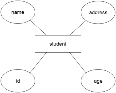
Fig 8: Example of ER
Component of ER model -
The following components are composed of an ER Diagram:
- Entity
- Attributes
- Relationships
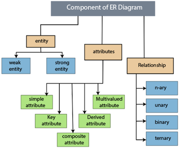
Fig 9: Component of ER model
1.Entity
The object, location, person, or event that stores data in the database may be an entity. In an object-relationship diagram, a rectangle represents an entity.
Examples of an individual include a student, course, boss, employee, patient, etc.

Fig 10: Entity
Entity type:
A list or a set of entities having certain common attributes is an entity type. In a database, a name and a list of attributes define each type of entity.
Entity set:
It is a set (or collection) of entities of the same kind that share attributes or related properties.
For example, it is possible to describe the category of individuals who are lecturers at a university as an entity-set lecturer. Similarly, the collection of students of the organization could represent the community of all university students.
2.Attribute
In an Entity-Relationship Model, an attribute defines an entity's properties or characteristics. It is represented in the ER diagram by an oval or ellipse shape. Each oval shape represents one attribute and is directly linked to the person that is in the shape of the rectangle.
For instance, the attributes defining the Employee form of entity are employee id, employee name, gender, employee age, salary, and mobile no.
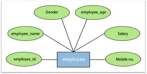
Fig 11: Different attributes of employee
In the ER model, the following categories can be defined by an attribute:
1.Simple attribute:
A simple attribute is called an attribute which contains an atomic value and can not be divided further. The gender and salary of a worker, for instance, is also depicted by an oval.
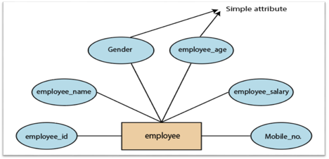
Fig 12: Simple attribute
2. Key attribute:
A key attribute is called an attribute that can uniquely identify an entity in an entity set. It represents a primary key in the ER diagram. In an Entity Relationship diagram, the key attribute is denoted by an oval with an underlying line. For example, for each employee, the employee id would be unique.
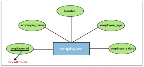
Fig 13: Key attributes
3. Composite attribute:
An attribute that is a combination of two or more basic attributes is called a composite attribute. It is defined by an ellipse in an Entity-Relationship diagram, and that ellipse consists of other ellipses. For example, an employee entity type's name attribute consists of first name, second name, and last name.
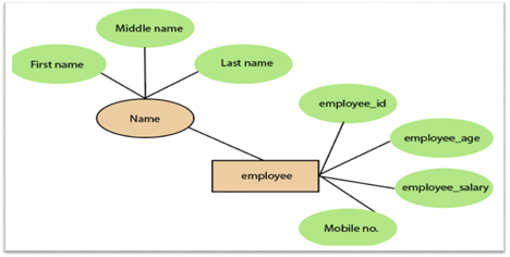
Fig 14: Composite attribute
4.Derived attribute:
A derived attribute is considered an attribute which can be derived from other attributes. In an entity-relationship diagram, a dashed oval shape is used to represent these attributes. Employee age is, for example, a derived attribute since it varies over time and can be derived from another DOB attribute (Date of birth).
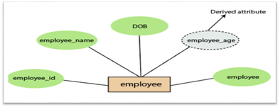
Fig 15: Derived attribute
5.Multivalued attributes:
An attribute which for a given entity contains more than one value. For instance, there may be more than one mobile number and email address for an employee.
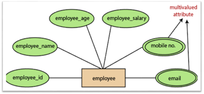
Fig 16: Multivalued attribute
3.Relationship
In the Entity-Relation Model, a relationship is used to define the relationship between two or more entities. In the ER diagram, it is illustrated by a diamond shape.
For example, in college student studies, employees work in a department. Here, the links are 'research in' and 'works in'.
Degree of Relationship
A partnership is called the degree of a relationship in which a variety of different individuals participate.
Degree of relationship can be categorized into the following types:
1. Unary Relationship:
A relationship in which a single group of individuals is involved is referred to as a unary relationship. For instance, in a company, an employee manages or supervises another employee.
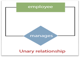
Fig 17: Unary relationship
2. Binary Relationship: When a relationship includes two people, it is considered a binary relationship.
3. Ternary Relationship: When a relationship contains three individual sets, a ternary relationship is called.
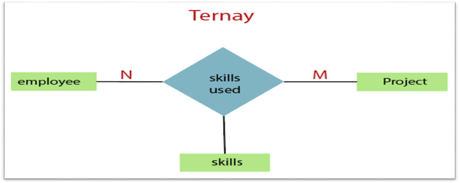
Fig 18: Ternary relationship
4. N-nary Relationship:
If a relationship includes more than three entity sets, an n-ary relationship is named.
Key takeaway:
- The object, location, person, or event that stores data in the database may be an entity.
- In an Entity-Relationship Model, an attribute defines an entity's properties or characteristics.
- Attributes are represented in the ER diagram by an oval or ellipse shape.
- In the Entity-Relation Model, a relationship is used to define the relationship between two or more entities.
The notations can be used to describe a database. Many notations are used to express cardinality in an ER diagram. The following are the notations:
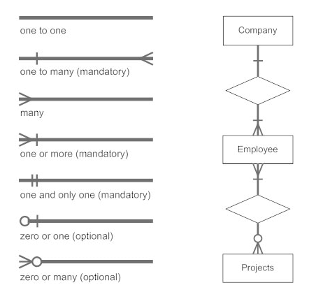
Fig 19: Notation of ER Diagram
● A mapping constraint is a data constraint representing the number of entities to which a relationship set can relate to another entity.
● It is most useful to define relationship sets involving more than two sets of individuals.
● There are four possible mapping cardinalities for the binary relationship set R on an entity set A and B. They are as follows
- One to one (1:1)
- One to many (1:M)
- Many to one (M:1)
- Many to many (M:M)
One to one: As we have seen in the example above, only one instance of an entity is mapped to one instance of another entity. Consider the Department's HOD. Just one HOD in one department exists. That is, the relationship between the HOD agency and the Department is 1:1.
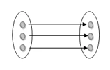
Fig 20: One to one mapping
One to many: As we can guess now, there is one instance of an entity linked to many instances of another entity between one and several relationships. In his department, one manager oversees several employees.
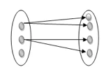
Fig 21: One to many mapping
Many to one: In a one-to-many mapping, an entity in E1 is linked to no more than one entity in E2, whereas an entity in E2 can be linked to any number of entities in E1.
Many to many: This is a relationship where multiple entity instances are linked to multiple entity instances.

Fig 22: Many to many mapping
Key takeaway:
- It is most useful to define relationship sets involving more than two sets of individuals.
- There are four possible mapping cardinalities for the binary relationship.
Keys are the entity's attributes, which define the entity's record uniquely.
Several types of keys exist.
These are listed underneath:
● Candidate key
A candidate key is a key that is simple or composite and special and minimal. It is special since no two rows can have the same value at any time in a table. It is minimal since, in order to achieve uniqueness, every column is required.
● Super key
The Super Key is one or more of the entity's attributes that uniquely define the database record.
● Primary key
The primary key is a candidate key that the database designer chooses to be used as an identification mechanism for the entire set of entities. In a table, it must uniquely classify tuples and not be null.
In the ER model, the primary key is indicated by underlining the attribute.
● To uniquely recognise tuples in a table, the designer selects a candidate key. It must not be empty.
● A key is selected by the database builder to be used by the entire entity collection as an authentication mechanism. This is regarded as the primary key. In the ER model, this key is indicated by underlining the attribute.
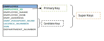
Fig 23: Shows different keys
● Alternate key
Alternate keys are all candidate keys not chosen as the primary key.
● Foreign key
A foreign key (FK) is an attribute in a table that, in another table, references the primary key OR it may be null. The same data type must be used for both international and primary keys.
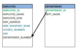
Fig 24: Foreign key
● Secondary key
A secondary key is an attribute used exclusively (can be composite) for retrieval purposes, such as: phone and last name.
● Composite key
A composite key consists of two attributes or more, but it must be minimal.
Key takeaway:
● Keys are the entity's attributes, which define the entity's record uniquely.
● A candidate key is a key that is simple or composite and special and minimal.
● Primary key, uniquely recognised tuples in a table, the designer selects a candidate key. It must not be empty.
● Generalization is similar to a bottom-up strategy in which two or more lower-level entities merge to form a higher-level entity if they share certain attributes.
● In general, an entity of a higher level may combine with entities of a lower level to create a new entity of a higher level.
● The approach to generalization is similar to that of the subclass and superclass systems. The bottom-up method is used in generalization.
● Entities are combined to form a more abstract entity in generalization, i.e., subclasses are combined to form a superclass.
For example, Faculty and Student entities may be combined to form the higher-level entity Individual.
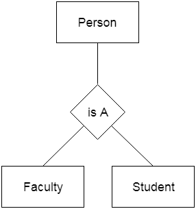
Fig 25: Generalization
Aggregation
The relationship between two entities is considered as a single entity in aggregation. Aggregation is the process of combining relationships with their related entities into a higher level entity.
For example, the Center entity provides the Course entity with the ability to function as a single entity in a relationship with another entity visitor. When a visitor visits a coaching center in the real world, he would never inquire about the Course or the Center alone; instead, he will inquire about both.
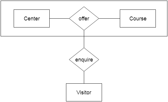
Fig 26: Aggregation
Key takeaway:
- Generalization is similar to a bottom-up strategy in which two or more lower-level entities merge to form a higher-level entity if they share certain attributes.
- Generalization is similar to a bottom-up strategy in which two or more lower-level entities merge to form a higher-level entity if they share certain attributes.
Using notations, the database can be represented, and these notations can be reduced to a set of tables.
Each entity set or relationship set can be represented in tabular form in the database.
The ER diagram is given below:
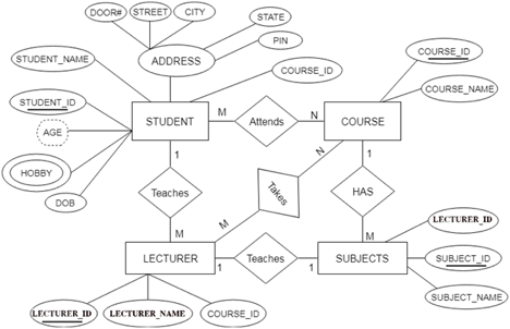
Fig 27: ER diagram
There are some points for converting the ER diagram to the table:
● Entity type becomes a table.
In the given ER diagram, LECTURE, STUDENT, SUBJECT and COURSE forms individual tables.
● All single-valued attributes become a column for the table.
In the STUDENT entity, STUDENT_NAME and STUDENT_ID form the column of STUDENT table. Similarly, COURSE_NAME and COURSE_ID form the column of COURSE table and so on.
● A key attribute of the entity type represented by the primary key.
In the given ER diagram, COURSE_ID, STUDENT_ID, SUBJECT_ID, and LECTURE_ID are the key attributes of the entity.
● The multivalued attribute is represented by a separate table.
A hobby is a multivalued feature inside the student table. Thus, multiple values cannot be expressed in a single column of the STUDENT table. We therefore generate a STUD HOBBY table with the STUDENT ID and HOBBY column names. We create a composite key by using both columns.
● Composite attribute represented by components.
Student address is a composite attribute in the given ER diagram. CITY, PIN, DOOR#, Path, and STATE are included. These attributes will merge as an individual column in the STUDENT table.
● Derived attributes are not considered in the table.
In the STUDENT table, the derived attribute is age. It can be determined by measuring the difference between the present date and the date of birth at any time.
You can convert the ER diagram to tables and columns using these rules and assign the mapping between the tables.
The following is the table structure for the given ER diagram:
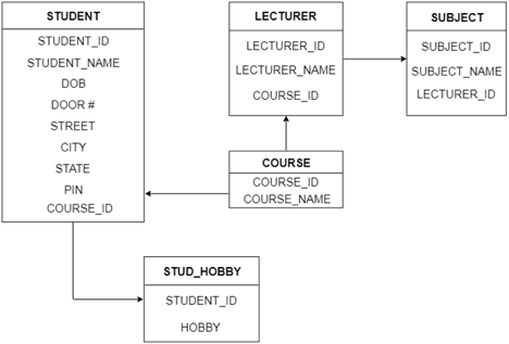
Fig 28: Table structure
Key takeaway:
- Each entity set or relationship set can be represented in tabular form in the database.
- Using notations, the database can be represented, and these notations can be reduced to a set of tables.
The Extended Entity-Relationship Model (EERM) is a more abstract and high-level model that expands the E/R model to include more forms of relationships and attributes, as well as to articulate constraints more clearly. The EE/R model includes all of the concepts found in the E/R model, as well as additional concepts that cover more semantic information.
In addition to ER model concepts EE-R includes −
● Subclasses and Superclasses.
● Specialization and Generalization.
● Category or union type.
● Aggregation.
These concepts are used to create EE-R diagrams.
Key takeaway:
- EER is a high-level data model that integrates the original ER model's extensions. Enhanced ERD models are high-level representations of the specifications and complexities of complex databases.
- Generalization/specialization, association, inheritance, and subclass / superclass are some of the additional definitions.
The number of occurrences in one entity that are correlated with the number of occurrences in another entity is known as the degree of relationship.
There are three types of relationships:
- One-to-one (1:1)
● One occurrence of one entity corresponds to one occurrence of another entity in a one-to-one relationship.
● In reality, a one-to-one partnership is uncommon.
2. One-to-many (1:M)
● One event in one entity corresponds to multiple occurrences in another entity in a one-to-many relationship.
3. Many-to-many (M:N)
● Many occurrences in one entity lead to many occurrences in another entity in a many-to-many relationship.
● The many-to-many relationship, like the one-to-one relationship, is uncommon in nature.
Key takeaway:
- The number of occurrences in one entity that are correlated with the number of occurrences in another entity is known as the degree of relationship.
References:
- Korth, Silbertz, Sudarshan,” Database Concepts”, McGraw Hill
- Date C J, “An Introduction to Database Systems”, Addision Wesley
- Elmasri, Navathe, “Fundamentals of Database Systems”, Addision Wesley
- O’Neil, Databases, Elsevier Pub.
Unit – 1
Introduction
Database
The database is a set of interrelated data used to efficiently retrieve, insert and remove data. It is also used in the form of a table, schema, views, and reports to organise the data, etc.
You can conveniently retrieve, attach, and delete information using the database.
Database management system (DBMS)
A DBMS is a programme that enables database creation, specification and manipulation, allowing users to easily store, process and analyse information.
DBMS provides one with an interface or a tool to conduct different operations, such as building databases, storing data in them, updating data, creating database tables, and much more.
The DBMS also provides databases with privacy and security. In the case of multiple users, it also ensures data consistency.
Some Example of DBMS:
● MySql
● Oracle
● SQL Server
● IBM DB2
Characteristics of DBMS
● Data stored into tables
● Reduced redundancy
● Query language
● Data consistency
● Security
● DBMS support transactions
● Support multiple user and concurrent access
Key takeaway:
- You can conveniently retrieve, attach, and delete information using the database.
- The DBMS provides databases with privacy and security.
- In the case of multiple users, it also ensures data consistency.
Difference between DBMS and file system, are as follows:
DBMS | File System |
A database management system is a collection of data. The user is not allowed to write procedures in a DBMS. | A file system is a data storage system. The user must write the database management procedures in this method. |
A database management system provides an abstract view of data that hides the information. | The data representation and storage of data are detailed in the file system.
|
A crash recovery mechanism is provided by DBMS, which protects the user from device failure. | The file system lacks a crash mechanism, which means that if the system crashes when entering data, the file's content will be lost. |
A good security mechanism is provided by DBMS. | Under the file system, protecting a file is extremely difficult. |
A database management system provides a broad range of advanced techniques for storing and retrieving data. | The file system is incapable of effectively storing and retrieving data. |
Concurrent data access is handled by DBMSs using some kind of locking.
| Concurrent access in the File system causes a number of issues, such as redirecting the file when others delete or update data. |
The architecture of a database management system influences its design. When dealing with a large number of PCs, web servers, database servers, and other networked elements, the same client/server architecture is used.
A client/server architecture is made up of several PCs and a workstation that are all linked by a network.
The design of a database management system is determined by how users link to the database in order to complete their requests.
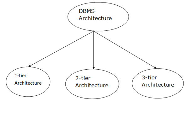
Fig 1: Types of architecture
A single tier or multi-tier database architecture can be seen. However, database design can be divided into two categories: 2-tier architecture and 3-tier architecture.
1-tier Architecture:
The database is directly accessible to the user in this architecture. It means that the user can sit on the DBMS and use it directly. Any modifications made here will be applied directly to the database. It does not provide end users with a useful tool.
For the creation of local applications, a 1-tier architecture is used, in which programmers can interact directly with the database for fast responses.
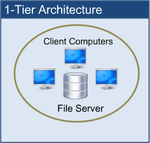
Fig 2: 1-tier architecture
2-tier Architecture:
The 2-tier architecture is similar to the basic client-server architecture. Client-side applications can interact directly with the database on the server side in a two-tier architecture. APIs such as ODBC and JDBC are used for this interaction.
The client-side runs the user interfaces and application programs. The server side is in charge of providing features such as query processing and transaction management. The client-side application creates a link with the server side in order to communicate with the DBMS.
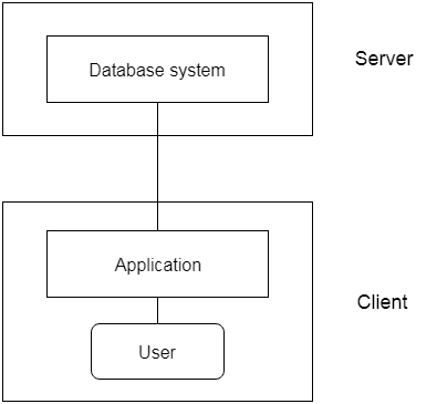
Fig 3: 2-tier architecture
3-tier Architecture:
Between the client and the server is another layer in the 3-tier architecture. The client cannot communicate directly with the server in this architecture. The client-side program communicates with an application server, which in turn communicates with the database system.
Beyond the application server, the end user is unaware of the database's presence. Aside from the submission, the database has no knowledge about any other users.
In the case of a wide web application, the 3-tier architecture is used.
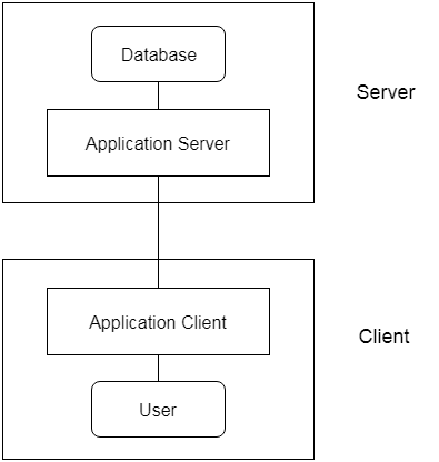
Fig 4: 3-tier architecture
● An instance of the database is the data that is stored in the database at a specific point in time.
● Schema refers to a database's overall configuration.
● A database schema is the database's skeleton structure. It reflects the entire database's logical view.
● Tables, foreign keys, primary keys, views, columns, data types, stored procedures, and other schema objects are included in a schema.
● The visual diagram can be used to describe a database schema. This diagram depicts the database objects and their relationships.
● Database schemas are created by database designers to assist programmers who will be working with the database. Data modeling is the term for the method of creating a database.
Only certain elements of a schema, such as the name of the record type, data type, and constraints, can be shown in a schema diagram. The schema diagram does not allow for the specification of other aspects. The provided figure, for example, does not indicate the data form of each data item or the relationship between the different files.
Actual data in the database is updated on a regular basis. When we add a new grade or a student, for example, the database shifts as seen in the diagram. The database instance refers to the data at a certain point in time.
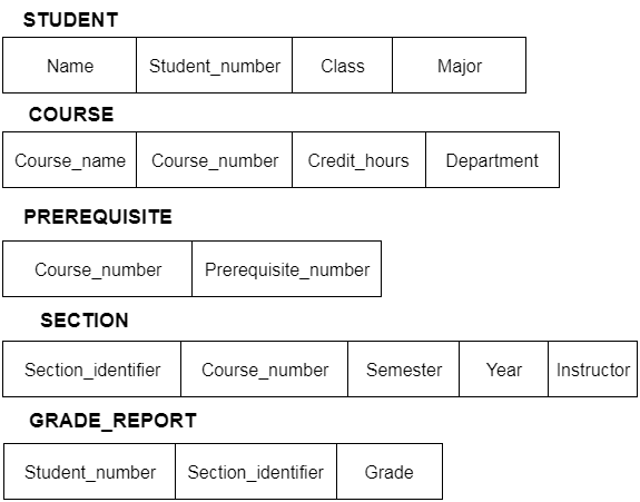
Fig 5: Schema diagram
In addition to users' data, a database system usually includes a lot of data. For instance, to easily locate and retrieve data, it stores information about data, known as metadata. Modifying or modifying a collection of metadata once it is placed in the database is very difficult. But when a DBMS expands, in order to fulfil the users' requirements, it needs to evolve over time. It will become a boring and highly complicated job if the entire data is based.
Metadata itself follows a layered model, such that it does not impact the data at another level when we modify data on one layer. This data is independent, but is mapped to one another.
Types of data independences
● Physical data independence
Physical Data Independence is defined as the ability to make adjustments without affecting the higher-level schemas in the structure of the lowest level of the Database Management System (DBMS). Therefore, the Physical level adjustment does not result in any adjustments to the Conceptual or View levels.
● Logical data independence
Logical Data Independence is defined as the ability to make improvements to the Database Management System (DBMS) middle level structure without affecting the schema or application programmes at the highest level. Changes to the conceptual level should also not result in any changes to the view levels or programmes of the application.
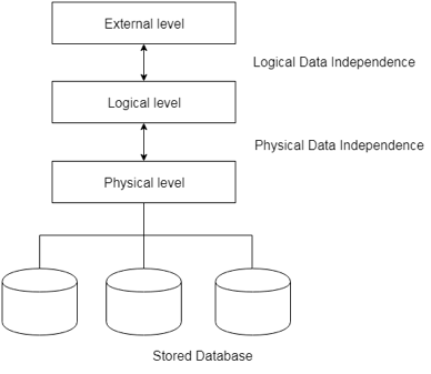
Fig 6: Data independence
Database language:
Users can interact with DBMS using database languages. There are two types of database languages:
1. The Data Definition Language (DDL)
2. The Data Manipulation Language (DML)
Interfaces
● Menu-based interfaces for Web clients or browsing
● Forms-based interfaces
● Graphical user interfaces
● Natural language interfaces
● Speech input and output
● Interfaces for parametric users
● Interfaces for the DBA
Key takeaway:
- The freedom of logical data refers to the ability to alter the conceptual schema without the external schema needing to be modified.
- Independence of physical data can be defined as the ability to alter the internal schema without the conceptual schema having to be modified.
In reality, the DDL or Data Definition Language consists of SQL commands that can be used to define the schema for the database. It basically deals with database schema definitions and is used to construct and change the configuration of database objects in the database.
Some of the commands that fall under DDL are as follows:
● CREATE
● ALTER
● DROP
● TRUNCATE
CREATE
It is used in the database for the development of a new table
Syntax
CREATE TABLE TABLE_NAME (COLUMN_NAME DATA TYPES[,....]);
Example
CREATE TABLE STUDENT(Name VARCHAR2(20), Address VARCHAR2(100), DOB DATE);
ALTER
It is used to modify the database structure. This move may be either to change the characteristics of an existing attribute or to add a new attribute, likely.
Syntax
In order to add a new column to the table:
ALTER TABLE table_name ADD column_name COLUMN-definition;
To change the current table column:
ALTER TABLE MODIFY(COLUMN DEFINITION....);
Example
ALTER TABLE STU_DETAILS ADD(ADDRESS VARCHAR2(20));
ALTER TABLE STU_DETAILS MODIFY (NAME VARCHAR2(20));
Drop
It is used to delete both the structure of the table and the record.
Syntax
DROP TABLE;
Example
DROP TABLE STUDENT;
TRUNCATE
It is used to erase from the table all rows and free up the space containing the table.
Syntax
TRUNCATE TABLE table_name;
Example
TRUNCATE TABLE STUDENT;
Data Manipulation Language (DML)
To change the database, DML commands are used. It is responsible for all forms of database changes.
The DML command is not auto-committed, which means all the changes in the database will not be permanently saved. There may be rollbacks.
Commands under DML
a. INSERT
The INSERT statement is a query from SQL. It is used for the insertion of data into a table row.
Syntax
INSERT INTO TABLE_NAME
(col1, col2, col3,.... Col N)
VALUES (value1, value2, value3, .... ValueN);
Or
INSERT INTO TABLE_NAME
VALUES (value1, value2, value3, .... ValueN);
b. UPDATE
This command is used to update or alter the value of a table column.
Syntax
UPDATE table_name SET [column_name1= value1,...column_nameN = valueN] [WHERE CONDITION]
c. DELETE
It is used to extract a table from one or more rows.
Syntax
DELETE FROM table_name [WHERE condition];
Types of DML: -
a. Procedural: -
It requires a user to specify what data is needed and how to retrieve it from the database. The user instructs the system to perform a sequence of options on the database to compute the desired result.
b. Non-Procedural: -
It requires a user to specify what data is needed without specifying how to get it.
Key takeaway:
- The DDL or Data Definition Language consists of SQL commands that can be used to define the schema for the database.
- To change the database, DML commands are used. It is responsible for all forms of database changes.
- The DML command is not auto-committed, which means all the changes in the database will not be permanently saved.
A system of databases is divided into modules dealing with each of the overall system's responsibilities. A database system's functional components can be narrowly divided into the components of the storage manager and the query processor. The storage manager is essential since a large amount of storage space is usually needed for databases. The query processor is important because it simplifies and promotes access to data by supporting the database system.
It is the responsibility of the database system to convert, at the logical level, changes and queries written in a non-procedural language into an effective sequence of physical level operations.
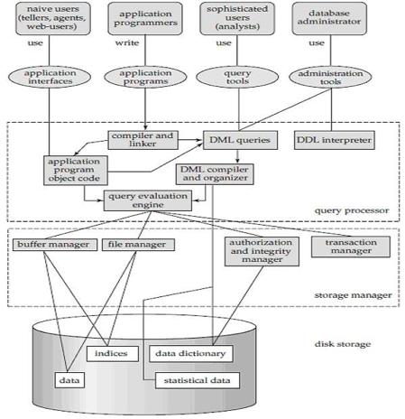
Fig 7: Overall structure of DBMS
The database system is divided into three components: Query Processor, Storage Manager, and Disk Storage
● Query processor
It interprets the requests (queries) received from the end user into instructions through an application programme. Also, the user request that is received from the DML compiler is executed.
The Query Processor comprises the following parts:
● DML compiler
The DML statements are processed into low-level (machine language) instructions so that they can be implemented.
● DDL interpreter
The DDL statements are processed into a table set containing metadata (data about data).
● Query optimization
Typically, a question can be converted into any of a variety of alternative assessment plans that all offer the same outcome. The DML compiler also performs query optimization, which is to say, among the alternatives, it selects the lowest cost evaluation plan.
● Query evaluation engine
That executes the low-level instructions that the DML compiler generates.
● Storage manager
A storage manager is a software module that provides an interface between the low-level data stored in the database and the system-submitted application programmes and queries. Interaction with the file manager is the responsibility of the storage manager. Using the file system, which is typically supported by a conventional operating system, raw data is stored on the disc. The storage manager converts the different DML statements into low-level commands for the file system. It is also the duty of the storage manager to store, retrieve, and update data in the database.
The components for the storage manager include:
● Authorization and integrity manager
This ensures role-based regulation of access, i.e., It checks whether or not the individual is entitled to conduct the requested activity.
When the database is updated, the integrity manager checks the integrity constraints.
● Transaction manager
It manages simultaneous access by executing the operations in a scheduled manner in which the transaction is received. It also ensures that the database stays in a consistent state before and after a transaction has been executed.
● File manager
It manages the space of the file and the data structure used in the database to represent information.
● Buffer manager
The cache memory and data transfer between the secondary storage and the main memory are responsible for this.
● Disk storage
It includes the following elements-
● Data files
It stores the data.
● Data dictionary
It includes details about any database object's structure. It is the information repository that regulates metadata.
● Indices
It provides faster retrieval of data items.
Key takeaway:
- A database system's functional components can be narrowly divided into the components of the storage manager and the query processor.
- A system of databases is divided into modules dealing with each of the overall system's responsibilities.
- The storage manager converts the different DML statements into low-level commands for the file system.
● The Entity-Relationship model (ER model) is a type of entity-relationship model. It's a data model at a high level. The data elements and relationships for a given system are described using this model.
● It creates a database's conceptual architecture. It also creates a very convenient and easy-to-design data view.
● The database structure is depicted as a diagram called an entity-relationship diagram in ER modeling.
Let's say we're creating a database for a school. The student will be an object in this database, with attributes such as address, name, id, age, and so on. There will be a relationship between the address and another entity with attributes such as city, street name, pin code, and so on.
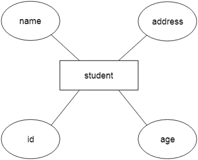
Fig 8: Example of ER
Component of ER model -
The following components are composed of an ER Diagram:
- Entity
- Attributes
- Relationships
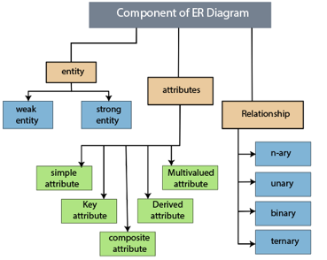
Fig 9: Component of ER model
1.Entity
The object, location, person, or event that stores data in the database may be an entity. In an object-relationship diagram, a rectangle represents an entity.
Examples of an individual include a student, course, boss, employee, patient, etc.

Fig 10: Entity
Entity type:
A list or a set of entities having certain common attributes is an entity type. In a database, a name and a list of attributes define each type of entity.
Entity set:
It is a set (or collection) of entities of the same kind that share attributes or related properties.
For example, it is possible to describe the category of individuals who are lecturers at a university as an entity-set lecturer. Similarly, the collection of students of the organization could represent the community of all university students.
2.Attribute
In an Entity-Relationship Model, an attribute defines an entity's properties or characteristics. It is represented in the ER diagram by an oval or ellipse shape. Each oval shape represents one attribute and is directly linked to the person that is in the shape of the rectangle.
For instance, the attributes defining the Employee form of entity are employee id, employee name, gender, employee age, salary, and mobile no.
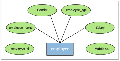
Fig 11: Different attributes of employee
In the ER model, the following categories can be defined by an attribute:
1.Simple attribute:
A simple attribute is called an attribute which contains an atomic value and can not be divided further. The gender and salary of a worker, for instance, is also depicted by an oval.
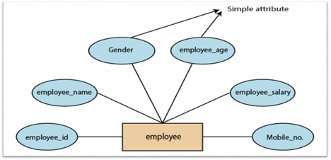
Fig 12: Simple attribute
2. Key attribute:
A key attribute is called an attribute that can uniquely identify an entity in an entity set. It represents a primary key in the ER diagram. In an Entity Relationship diagram, the key attribute is denoted by an oval with an underlying line. For example, for each employee, the employee id would be unique.
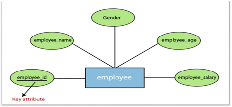
Fig 13: Key attributes
3. Composite attribute:
An attribute that is a combination of two or more basic attributes is called a composite attribute. It is defined by an ellipse in an Entity-Relationship diagram, and that ellipse consists of other ellipses. For example, an employee entity type's name attribute consists of first name, second name, and last name.
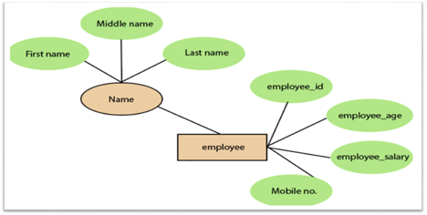
Fig 14: Composite attribute
4.Derived attribute:
A derived attribute is considered an attribute which can be derived from other attributes. In an entity-relationship diagram, a dashed oval shape is used to represent these attributes. Employee age is, for example, a derived attribute since it varies over time and can be derived from another DOB attribute (Date of birth).
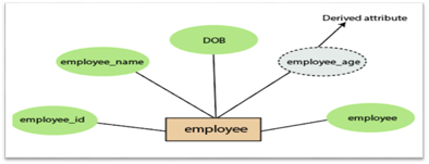
Fig 15: Derived attribute
5.Multivalued attributes:
An attribute which for a given entity contains more than one value. For instance, there may be more than one mobile number and email address for an employee.
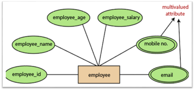
Fig 16: Multivalued attribute
3.Relationship
In the Entity-Relation Model, a relationship is used to define the relationship between two or more entities. In the ER diagram, it is illustrated by a diamond shape.
For example, in college student studies, employees work in a department. Here, the links are 'research in' and 'works in'.
Degree of Relationship
A partnership is called the degree of a relationship in which a variety of different individuals participate.
Degree of relationship can be categorized into the following types:
1. Unary Relationship:
A relationship in which a single group of individuals is involved is referred to as a unary relationship. For instance, in a company, an employee manages or supervises another employee.
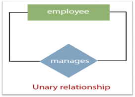
Fig 17: Unary relationship
2. Binary Relationship: When a relationship includes two people, it is considered a binary relationship.
3. Ternary Relationship: When a relationship contains three individual sets, a ternary relationship is called.
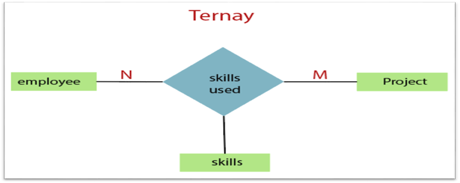
Fig 18: Ternary relationship
4. N-nary Relationship:
If a relationship includes more than three entity sets, an n-ary relationship is named.
Key takeaway:
- The object, location, person, or event that stores data in the database may be an entity.
- In an Entity-Relationship Model, an attribute defines an entity's properties or characteristics.
- Attributes are represented in the ER diagram by an oval or ellipse shape.
- In the Entity-Relation Model, a relationship is used to define the relationship between two or more entities.
The notations can be used to describe a database. Many notations are used to express cardinality in an ER diagram. The following are the notations:
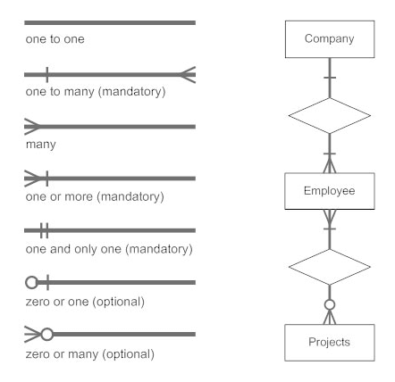
Fig 19: Notation of ER Diagram
● A mapping constraint is a data constraint representing the number of entities to which a relationship set can relate to another entity.
● It is most useful to define relationship sets involving more than two sets of individuals.
● There are four possible mapping cardinalities for the binary relationship set R on an entity set A and B. They are as follows
- One to one (1:1)
- One to many (1:M)
- Many to one (M:1)
- Many to many (M:M)
One to one: As we have seen in the example above, only one instance of an entity is mapped to one instance of another entity. Consider the Department's HOD. Just one HOD in one department exists. That is, the relationship between the HOD agency and the Department is 1:1.
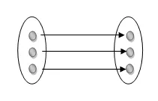
Fig 20: One to one mapping
One to many: As we can guess now, there is one instance of an entity linked to many instances of another entity between one and several relationships. In his department, one manager oversees several employees.
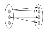
Fig 21: One to many mapping
Many to one: In a one-to-many mapping, an entity in E1 is linked to no more than one entity in E2, whereas an entity in E2 can be linked to any number of entities in E1.
Many to many: This is a relationship where multiple entity instances are linked to multiple entity instances.

Fig 22: Many to many mapping
Key takeaway:
- It is most useful to define relationship sets involving more than two sets of individuals.
- There are four possible mapping cardinalities for the binary relationship.
Keys are the entity's attributes, which define the entity's record uniquely.
Several types of keys exist.
These are listed underneath:
● Candidate key
A candidate key is a key that is simple or composite and special and minimal. It is special since no two rows can have the same value at any time in a table. It is minimal since, in order to achieve uniqueness, every column is required.
● Super key
The Super Key is one or more of the entity's attributes that uniquely define the database record.
● Primary key
The primary key is a candidate key that the database designer chooses to be used as an identification mechanism for the entire set of entities. In a table, it must uniquely classify tuples and not be null.
In the ER model, the primary key is indicated by underlining the attribute.
● To uniquely recognise tuples in a table, the designer selects a candidate key. It must not be empty.
● A key is selected by the database builder to be used by the entire entity collection as an authentication mechanism. This is regarded as the primary key. In the ER model, this key is indicated by underlining the attribute.
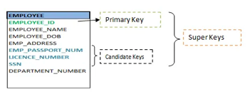
Fig 23: Shows different keys
● Alternate key
Alternate keys are all candidate keys not chosen as the primary key.
● Foreign key
A foreign key (FK) is an attribute in a table that, in another table, references the primary key OR it may be null. The same data type must be used for both international and primary keys.
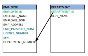
Fig 24: Foreign key
● Secondary key
A secondary key is an attribute used exclusively (can be composite) for retrieval purposes, such as: phone and last name.
● Composite key
A composite key consists of two attributes or more, but it must be minimal.
Key takeaway:
● Keys are the entity's attributes, which define the entity's record uniquely.
● A candidate key is a key that is simple or composite and special and minimal.
● Primary key, uniquely recognised tuples in a table, the designer selects a candidate key. It must not be empty.
● Generalization is similar to a bottom-up strategy in which two or more lower-level entities merge to form a higher-level entity if they share certain attributes.
● In general, an entity of a higher level may combine with entities of a lower level to create a new entity of a higher level.
● The approach to generalization is similar to that of the subclass and superclass systems. The bottom-up method is used in generalization.
● Entities are combined to form a more abstract entity in generalization, i.e., subclasses are combined to form a superclass.
For example, Faculty and Student entities may be combined to form the higher-level entity Individual.
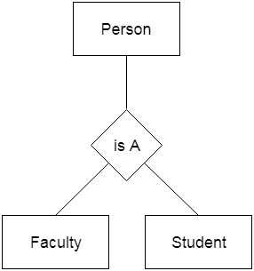
Fig 25: Generalization
Aggregation
The relationship between two entities is considered as a single entity in aggregation. Aggregation is the process of combining relationships with their related entities into a higher level entity.
For example, the Center entity provides the Course entity with the ability to function as a single entity in a relationship with another entity visitor. When a visitor visits a coaching center in the real world, he would never inquire about the Course or the Center alone; instead, he will inquire about both.
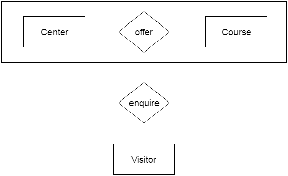
Fig 26: Aggregation
Key takeaway:
- Generalization is similar to a bottom-up strategy in which two or more lower-level entities merge to form a higher-level entity if they share certain attributes.
- Generalization is similar to a bottom-up strategy in which two or more lower-level entities merge to form a higher-level entity if they share certain attributes.
Using notations, the database can be represented, and these notations can be reduced to a set of tables.
Each entity set or relationship set can be represented in tabular form in the database.
The ER diagram is given below:
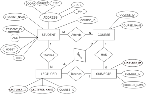
Fig 27: ER diagram
There are some points for converting the ER diagram to the table:
● Entity type becomes a table.
In the given ER diagram, LECTURE, STUDENT, SUBJECT and COURSE forms individual tables.
● All single-valued attributes become a column for the table.
In the STUDENT entity, STUDENT_NAME and STUDENT_ID form the column of STUDENT table. Similarly, COURSE_NAME and COURSE_ID form the column of COURSE table and so on.
● A key attribute of the entity type represented by the primary key.
In the given ER diagram, COURSE_ID, STUDENT_ID, SUBJECT_ID, and LECTURE_ID are the key attributes of the entity.
● The multivalued attribute is represented by a separate table.
A hobby is a multivalued feature inside the student table. Thus, multiple values cannot be expressed in a single column of the STUDENT table. We therefore generate a STUD HOBBY table with the STUDENT ID and HOBBY column names. We create a composite key by using both columns.
● Composite attribute represented by components.
Student address is a composite attribute in the given ER diagram. CITY, PIN, DOOR#, Path, and STATE are included. These attributes will merge as an individual column in the STUDENT table.
● Derived attributes are not considered in the table.
In the STUDENT table, the derived attribute is age. It can be determined by measuring the difference between the present date and the date of birth at any time.
You can convert the ER diagram to tables and columns using these rules and assign the mapping between the tables.
The following is the table structure for the given ER diagram:
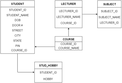
Fig 28: Table structure
Key takeaway:
- Each entity set or relationship set can be represented in tabular form in the database.
- Using notations, the database can be represented, and these notations can be reduced to a set of tables.
The Extended Entity-Relationship Model (EERM) is a more abstract and high-level model that expands the E/R model to include more forms of relationships and attributes, as well as to articulate constraints more clearly. The EE/R model includes all of the concepts found in the E/R model, as well as additional concepts that cover more semantic information.
In addition to ER model concepts EE-R includes −
● Subclasses and Superclasses.
● Specialization and Generalization.
● Category or union type.
● Aggregation.
These concepts are used to create EE-R diagrams.
Key takeaway:
- EER is a high-level data model that integrates the original ER model's extensions. Enhanced ERD models are high-level representations of the specifications and complexities of complex databases.
- Generalization/specialization, association, inheritance, and subclass / superclass are some of the additional definitions.
The number of occurrences in one entity that are correlated with the number of occurrences in another entity is known as the degree of relationship.
There are three types of relationships:
- One-to-one (1:1)
● One occurrence of one entity corresponds to one occurrence of another entity in a one-to-one relationship.
● In reality, a one-to-one partnership is uncommon.
2. One-to-many (1:M)
● One event in one entity corresponds to multiple occurrences in another entity in a one-to-many relationship.
3. Many-to-many (M:N)
● Many occurrences in one entity lead to many occurrences in another entity in a many-to-many relationship.
● The many-to-many relationship, like the one-to-one relationship, is uncommon in nature.
Key takeaway:
- The number of occurrences in one entity that are correlated with the number of occurrences in another entity is known as the degree of relationship.
References:
- Korth, Silbertz, Sudarshan,” Database Concepts”, McGraw Hill
- Date C J, “An Introduction to Database Systems”, Addision Wesley
- Elmasri, Navathe, “Fundamentals of Database Systems”, Addision Wesley
- O’Neil, Databases, Elsevier Pub.