Unit - 4
Computer Arithmetic
Addition and Subtraction with Signed –Magnitude Data
The magnitude of the two numbers is denoted by the letters A and B. There are eight different requirements to consider when signed numbers are added or subtracted, depending on the sign of the numbers and the operation done. Table's first column has a list of these requirements. The table's other columns depict the actual procedure to be carried out, together with the size of the figures. To exhibit a negative zero, the last column is required. In other words, the outcome of subtracting two equal values should be +0, not -0.
The addition and subtraction methods are obtained from the table and are as follows(the words parentheses should be used for the subtraction algorithm).


Fig 1: Signed Magnitude Addition and Subtraction and hardware implementation
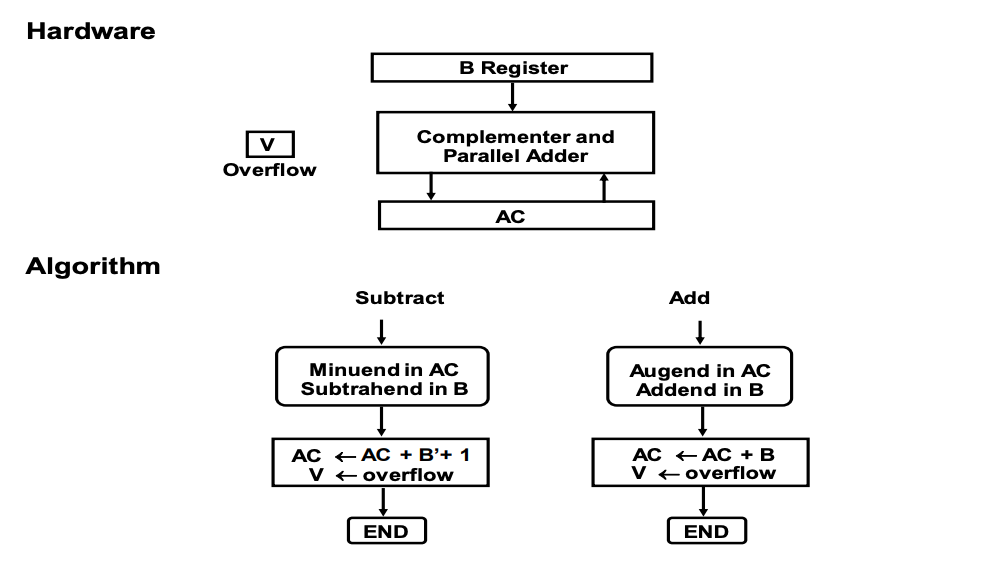
Fig 2: 2’s complements addition and subtraction
Algorithm
• Figure depicts the flowchart. An exclusive-OR gate compares the two indicators A and B.
◦ The signs are identical if the gate output is 0; if it is 1, the signals are different.
• The magnitudes must be added in an add operation because the signs are same. Different signs demand that the magnitudes be added in a subtract operation.
• The magnitudes are combined using the EA A + B micro operation, where EA is a register that combines E and A. If the carry in E after the addition is equal to 1, it is an overflow. In the add-overflow flip-flop AVF, the value of E is transferred.
• If the signs are different for an add operation or identical for a subtract operation, the two magnitudes are subtracted. By adding A to the 2's complementing B, the magnitudes are removed. If the numbers are removed, there will be no overflow and AVF will be cleared to 0.
• The value in A is the right answer, while 1 in E shows that A >= B. To avoid a negative zero, the sign A must be made positive if this numbs is zero.
• E with a value of 0 denotes that A is greater than B. It is essential to take the 2's complement of the value in A in this scenario. One micro action, A A' +1, is all that is required to complete the operation.
• We presume, however, that the A register comprises circuits for complement and increment micro operations, thus the 2's complement is produced from these two micro operations.
• The sign of the result in other flowchart pathways is the same as the sign of A, thus there is no need to modify A. When A B, however, the result's sign is the complement of A's initial sign. The correct sign must then be obtained by complementing A.
• The ultimate result may be found in register A, and its sign can be found in register As. Overflow is indicated by the value in AVF. It makes no difference what E's final value is.
• A block diagram of the hardware for performing addition and subtraction operations is shown in Figure 1.
◦ It comprises of registers A and B, as well as As and Bs sign flip-flops.
◦ Subtraction is accomplished by multiplying A by B's 2's complement.
• The output carry is sent to flip-flop E, where it can be compared to two values to determine their relative magnitudes.
• When A and B are added, the add-overflow flip-flop AVF holds the overflow bit.
• Other micro operations that may be required while specifying the sequence of steps in the algorithm are provided by the A register.
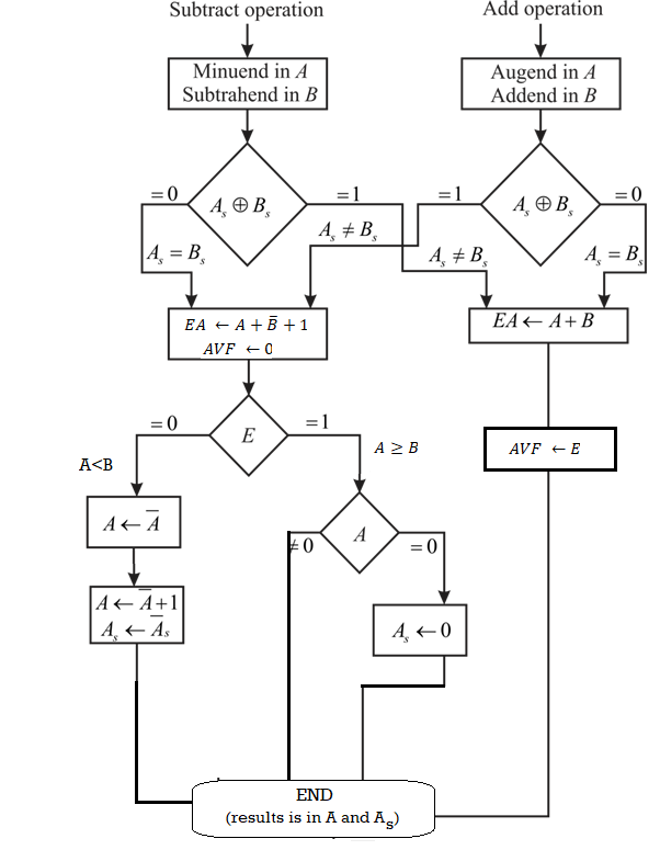
Fig 3: Flowchart for add and subtract operation
Key takeaway
The magnitude of the two numbers is denoted by the letters A and B. There are eight different requirements to consider when signed numbers are added or subtracted, depending on the sign of the numbers and the operation done.
The booth algorithm is a multiplication algorithm that allows us to multiply the two signed binary integers in 2's complement, respectively. It is also used to speed up the performance of the multiplication process. It is very efficient too. It works on the string bits 0's in the multiplier that requires no additional bit only shift the right-most string bits and a string of 1's in a multiplier bit weight 2k to weight 2m that can be considered as 2k+ 1 - 2m.
Following is the pictorial representation of the Booth's Algorithm:
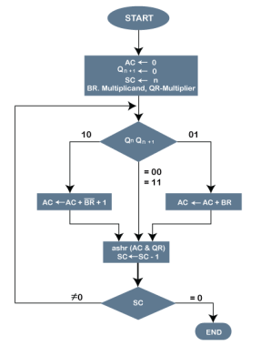
Fig 4- Pictorial representation of the Booth's Algorithm
In the above flowchart, initially, AC and Qn + 1 bits are set to 0, and the SC is a sequence counter that represents the total bits set n, which is equal to the number of bits in the multiplier. There are BR that represent the multiplicand bits, and QR represents the multiplier bits. After that, we encountered two bits of the multiplier as Qn and Qn + 1, where Qn represents the last bit of QR, and Qn + 1 represents the incremented bit of Qn by 1. Suppose two bits of the multiplier is equal to 10; it means that we have to subtract the multiplier from the partial product in the accumulator AC and then perform the arithmetic shift operation (ashr). If the two of the multipliers equal to 01, it means we need to perform the addition of the multiplicand to the partial product in accumulator AC and then perform the arithmetic shift operation (ashr), including Qn + 1. The arithmetic shift operation is used in Booth's algorithm to shift AC and QR bits to the right by one and remains the sign bit in AC unchanged. And the sequence counter is continuously decremented till the computational loop is repeated, equal to the number of bits (n).
Working on the Booth Algorithm
- Set the Multiplicand and Multiplier binary bits as M and Q, respectively.
- Initially, we set the AC and Qn + 1 registers value to 0.
- SC represents the number of Multiplier bits (Q), and it is a sequence counter that is continuously decremented till equal to the number of bits (n) or reached to 0.
- A Qn represents the last bit of the Q, and the Qn+1 shows the incremented bit of Qn by 1.
- On each cycle of the booth algorithm, Qn and Qn + 1 bits will be checked on the following parameters as follows:
- When two bits Qn and Qn + 1 are 00 or 11, we simply perform the arithmetic shift right operation (ashr) to the partial product AC. And the bits of Qn and Qn + 1 is incremented by 1 bit.
- If the bits of Qn and Qn + 1 is shows to 01, the multiplicand bits (M) will be added to the AC (Accumulator register). After that, we perform the right shift operation to the AC and QR bits by 1.
- If the bits of Qn and Qn + 1 is shows to 10, the multiplicand bits (M) will be subtracted from the AC (Accumulator register). After that, we perform the right shift operation to the AC and QR bits by 1.
- The operation continuously works till we reached n - 1 bit in the booth algorithm.
- Results of the Multiplication binary bits will be stored in the AC and QR registers.
There are two methods used in Booth's Algorithm:
1. RSC (Right Shift Circular)
It shifts the right-most bit of the binary number, and then it is added to the beginning of the binary bits.
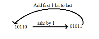
2. RSA (Right Shift Arithmetic)
It adds the two binary bits and then shift the result to the right by 1-bit position.
Example: 0100 + 0110 => 1010, after adding the binary number shift each bit by 1 to the right and put the first bit of resultant to the beginning of the new bit.
Example: Multiply the two numbers 7 and 3 by using the Booth's multiplication algorithm.
Ans. Here we have two numbers, 7 and 3. First of all, we need to convert 7 and 3 into binary numbers like 7 = (0111) and 3 = (0011). Now set 7 (in binary 0111) as multiplicand (M) and 3 (in binary 0011) as a multiplier (Q). And SC (Sequence Count) represents the number of bits, and here we have 4 bits, so set the SC = 4. Also, it shows the number of iteration cycles of the booth's algorithms and then cycles run SC = SC - 1 time.
Qn | Qn + 1 | M = (0111) | AC | Q | Qn + 1 | SC |
1 | 0 | Initial | 0000 | 0011 | 0 | 4 |
|
| Subtract (M' + 1) | 1001 |
|
|
|
|
|
| 1001 |
|
|
|
|
| Perform Arithmetic Right Shift operations (ashr) | 1100 | 1001 | 1 | 3 |
1 | 1 | Perform Arithmetic Right Shift operations (ashr) | 1110 | 0100 | 1 | 2 |
0 | 1 | Addition (A + M) | 0111 |
|
|
|
|
|
| 0101 | 0100 |
|
|
|
| Perform Arithmetic right shift operation | 0010 | 1010 | 0 | 1 |
0 | 0 | Perform Arithmetic right shift operation | 0001 | 0101 | 0 | 0 |
The numerical example of the Booth's Multiplication Algorithm is 7 x 3 = 21 and the binary representation of 21 is 10101. Here, we get the resultant in binary 00010101. Now we convert it into decimal, as (000010101)10 = 2*4 + 2*3 + 2*2 + 2*1 + 2*0 => 21.
Example: Multiply the two numbers 23 and -9 by using the Booth's multiplication algorithm.
Here, M = 23 = (010111) and Q = -9 = (110111)
Qn Qn + 1 | M = 0 1 0 1 1 1 | AC | Q | Qn + 1 SC |
| Initially | 000000 | 110111 | 0 6 |
1 0 | Subtract M | 101001 |
|
|
|
| 101001 |
|
|
| Perform Arithmetic right shift operation | 110100 | 111011 | 1 5 |
1 1 | Perform Arithmetic right shift operation | 111010 | 011101 | 1 4 |
1 1 | Perform Arithmetic right shift operation | 111101 | 001110 | 1 3 |
0 1 | Addition (A + M) | 010111 |
|
|
|
| 010100 |
|
|
| Perform Arithmetic right shift operation | 001010 | 000111 | 0 2 |
1 0 | Subtract M | 101001 |
|
|
|
| 110011 |
|
|
| Perform Arithmetic right shift operation | 111001 | 100011 | 1 1 |
1 1 | Perform Arithmetic right shift operation | 111100 | 110001 | 1 0 |
Qn + 1 = 1, it means the output is negative.
Hence, 23 * -9 = 2's complement of 111100110001 => (00001100111)
Key takeaway
The booth algorithm is a multiplication algorithm that allows us to multiply the two signed binary integers in 2's complement, respectively. It is also used to speed up the performance of the multiplication process. It is very efficient too. It works on the string bits 0's in the multiplier that requires no additional bit only shift the right-most string bits and a string of 1's in a multiplier bit weight 2k to weight 2m that can be considered as 2k+ 1 - 2m.
In division algorithm dividend will be greater than or equal to zero, overflow condition occurs when flipflop is set we call it divide overflow flipflop and label it DVF
To avoid DVF floating point data can be used
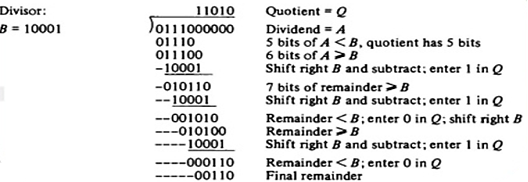
Hardware Algorithm
Dividend is in A and Q and the divisor in B, the sign of the result is transferred into Qs to be part of quotient
Overflow condition is tested by subtracting divisor in B from half of the bits of the dividend stored in A
If A>B the divide overflow flip flop DVF is set and the operation is terminated
As shown in flowchart the quotient magnitude is formed in register Q and the remainder is found in the register A
Quotient sign is in QS and the sign of the remainder in AS is same as the original sign of the dividend
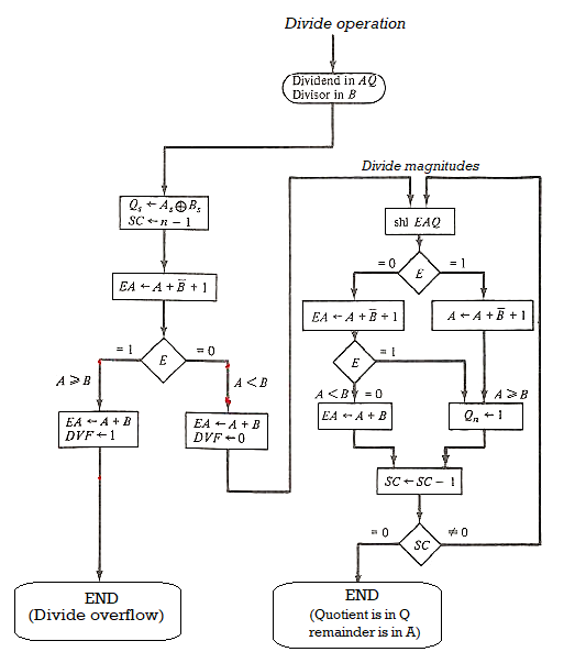
Figure 5 - Hardware Algorithm for Division
INSTRUCTION SET:
Instruction set or Instruction Set Architecture (ISA) is the part of the processor that is visible to the programmer or compiler writer.
The ISA serves as the boundary between software and hardware.
The ISA defines the types of instructions to be supported by the processor. Instructions are classified into 3 types:
- Arithmetic/Logic Instructions: These Instructions perform various Arithmetic & logical operations on one or more operands
- Data Transfer Instructions: These Instructions are responsible for the transfer of instruction from memory to the processor registers and vice versa
- Branch and jump Instructions: These Instructions are responsible for breaking the sequential flow of instruction and jumping to instructions at various other locations for the implementation of functions and conditional statements
Key takeaway
In division algorithm dividend will be greater than or equal to zero, overflow condition occurs when flipflop is set we call it divide overflow flipflop and label it DVF
To avoid DVF floating point data can be used
References:
- Computer System Architecture by Morris Mano, Prenticehall, 3rd Edition, (2007)
- Computer Organization by Carl Hamacher, ZvonkoVranesic, SafwatZaky, Tata Mcgraw Hill, 5th Edition, (2011)
- Computer Architecture: A Quantitative Approach by Hennessy, J. L, David A Patterson, and Goldberg, Pearson Education, 4th Edition, (2006)