Unit - 6
Introduction to Parallel Processing
The term Pipelining refers to a technique of decomposing a sequential process into sub-operations, with each sub-operation being executed in a dedicated segment that operates concurrently with all other segments.
The most important characteristic of a pipeline technique is that several computations can be in progress in distinct segments at the same time. The overlapping of computation is made possible by associating a register with each segment in the pipeline. The registers provide isolation between each segment so that each can operate on distinct data simultaneously.
The structure of a pipeline organization can be represented simply by including an input register for each segment followed by a combinational circuit.
Let us consider an example of combined multiplication and addition operation to get a better understanding of the pipeline organization.
The combined multiplication and addition operation is done with a stream of numbers such as:
Ai* Bi + Ci for i = 1, 2, 3, ......., 7
The operation to be performed on the numbers is decomposed into sub-operations with each sub-operation to be implemented in a segment within a pipeline.
The sub-operations performed in each segment of the pipeline are defined as:
R1 ← Ai, R2 ← Bi Input Ai, and Bi
R3 ← R1 * R2, R4 ← Ci Multiply, and input Ci
R5 ← R3 + R4 Add Ci to product
The following block diagram represents the combined as well as the sub-operations performed in each segment of the pipeline.
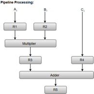
Fig – Pipeline process
Registers R1, R2, R3, and R4 hold the data and the combinational circuits operate in a particular segment.
The output generated by the combinational circuit in a given segment is applied as an input register of the next segment. For instance, from the block diagram, we can see that the register R3 is used as one of the input registers for the combinational adder circuit.
In general, the pipeline organization is applicable for two areas of computer design which includes:
- Arithmetic Pipeline
- Instruction Pipeline
Instruction Pipeline
Pipeline processing can occur not only in the data stream but in the instruction stream as well.
Most of the digital computers with complex instructions require instruction pipeline to carry out operations like fetch, decode and execute instructions.
In general, the computer needs to process each instruction with the following sequence of steps.
- Fetch instruction from memory.
- Decode the instruction.
- Calculate the effective address.
- Fetch the operands from memory.
- Execute the instruction.
- Store the result in the proper place.
Each step is executed in a particular segment, and there are times when different segments may take different times to operate on the incoming information. Moreover, there are times when two or more segments may require memory access at the same time, causing one segment to wait until another is finished with the memory.
The organization of an instruction pipeline will be more efficient if the instruction cycle is divided into segments of equal duration. One of the most common examples of this type of organization is a Four-segment instruction pipeline.
A four-segment instruction pipeline combines two or more different segments and makes it as a single one. For instance, the decoding of the instruction can be combined with the calculation of the effective address into one segment.
The following block diagram shows a typical example of a four-segment instruction pipeline. The instruction cycle is completed in four segments.
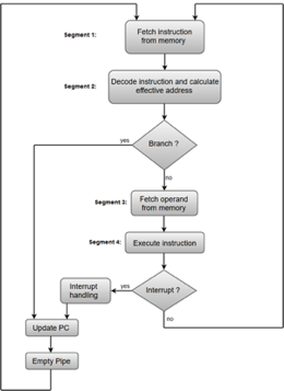
Fig – Instruction Cycle
Segment 1:
The instruction fetch segment can be implemented using first in, first out (FIFO) buffer.
Segment 2:
The instruction fetched from memory is decoded in the second segment, and eventually, the effective address is calculated in a separate arithmetic circuit.
Segment 3:
An operand from memory is fetched in the third segment.
Segment 4:
The instructions are finally executed in the last segment of the pipeline organization.
Arithmetic Pipeline
Arithmetic Pipelines are mostly used in high-speed computers. They are used to implement floating-point operations, multiplication of fixed-point numbers, and similar computations encountered in scientific problems.
To understand the concepts of arithmetic pipeline in a more convenient way, let us consider an example of a pipeline unit for floating-point addition and subtraction.
The inputs to the floating-point adder pipeline are two normalized floating-point binary numbers defined as:
X = A * 2a = 0.9504 * 103
Y = B * 2b = 0.8200 * 102
Where A and B are two fractions that represent the mantissa and a and b are the exponents.
The combined operation of floating-point addition and subtraction is divided into four segments. Each segment contains the corresponding sub operation to be performed in the given pipeline. The sub operations that are shown in the four segments are:
- Compare the exponents by subtraction.
- Align the mantissas.
- Add or subtract the mantissas.
- Normalize the result.
The following block diagram represents the sub operations performed in each segment of the pipeline.

Fig – Sub Operations
Note: Registers are placed after each sub operation to store the intermediate results.
1. Compare exponents by subtraction:
The exponents are compared by subtracting them to determine their difference. The larger exponent is chosen as the exponent of the result.
The difference of the exponents, i.e., 3 - 2 = 1 determines how many times the mantissa associated with the smaller exponent must be shifted to the right.
2. Align the mantissas:
The mantissa associated with the smaller exponent is shifted according to the difference of exponents determined in segment one.
X = 0.9504 * 103
Y = 0.08200 * 103
3. Add mantissas:
The two mantissas are added in segment three.
Z = X + Y = 1.0324 * 103
4. Normalize the result:
After normalization, the result is written as:
Z = 0.1324 * 104
Key takeaway
The term Pipelining refers to a technique of decomposing a sequential process into sub-operations, with each sub-operation being executed in a dedicated segment that operates concurrently with all other segments.
The most important characteristic of a pipeline technique is that several computations can be in progress in distinct segments at the same time. The overlapping of computation is made possible by associating a register with each segment in the pipeline. The registers provide isolation between each segment so that each can operate on distinct data simultaneously.
● A multi processor is a system that connects two or more CPUs, memory, and input-output devices.
● In a multiprocessor system, the term processor can refer to either a central processing unit (CPU) or an input-output processor (IOP).
● Multiple instruction stream multiple data stream (MIMD) systems are used to classify multiprocessors.
● The primary difference between a multicomputer and a multiprocessor system is that in a multicomputer system, computers are connected to form a network and may or may not communicate with one another.
● A multiprocessor system is managed by a single operating system that allows processors to communicate with one another, and all of the system's components work together to solve a problem.
● Multiprocessing increases system reliability by limiting the impact of a breakdown in one element on the remainder of the system.
● If one processor fails due to a malfunction, another processor might be allocated to take over the functions of the disabled processor.
● Improved system performance is one of the advantages of a multiprocessor setup.
● By dividing a program into concurrent executable tasks, multiprocessing can enhance performance.
● This can be accomplished in two ways.
● The user can designate that particular tasks should be run in parallel.
● Another efficient method is to provide a compiler that can detect parallelism in a user's program automatically.
● The compiler examines the program for data dependencies.
● If a program relies on data from another portion, the part that generates the data must be run first.
● Two components of a program that don't use each other's data can execute at the same time.
Depending on the number of transfer channels available between the processors and memory in a shared memory system and among the processing elements in a loosely linked system, the interconnection between the components of a multiprocessor system can have varied physical configurations.
There are a variety of physical forms that can be used to create an interconnection network.
● Time-shared common bus
● Multiport memory
● Crossbar switch
● Multistage switching network
● Hypercube system
Time shared common bus
● A multiprocessor system with a common bus consists of a number of processors connected to a memory unit over a common channel.
● A common bus (or buses) connects all processors (and memory). Memory access is very consistent, but it isn't particularly scalable. Module-to-module communication is carried out across a network of signal wires. Several digital system parts are connected by data highways.
● A cache memory attached to the CPU could be part of the local memory.

Fig: Time shared common bus

Fig: System bus structure for multiprocessor
We have a number of local buses to its own local memory and one or more processors in the diagram above. A CPU, an IOP, or any combination of processors can be attached to each local bus. Each local bus is connected to a common system bus by a system bus controller. The local processor has access to the I/O devices linked to the local IOP, as well as the local memory. All processors share the memory attached to the same system bus. The I/O devices attached to an IOP that is directly connected to the system bus may be made available to all processors.
Disadvantages
● At any given time, only one processor can connect with the memory or another processor.
● As a result, the system's entire overall transfer rate is constrained by the single path's speed.
Multiport memory
● Each memory module and each CPU are connected by independent buses in a multiport memory system.
● Internal control logic must be present in the module to identify which port has access to memory at any given time.
● Each memory port has a predetermined priority, which is used to handle memory access conflicts.
Advantages:
- Because of the many pathways, a high transfer rate can be accomplished.
Disadvantages:
- It necessitates costly memory control logic as well as a significant number of cables and connectors.
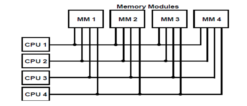
Fig: Multiport memory
Crossbar switch
● A number of crosspoints are located at the intersections of processor buses and memory module routes.
● Each crosspoint has a little square that determines the path from a CPU to a memory module.
● Each switch point has control logic for configuring the processor-to-memory transfer path.
● It also prioritizes requests for access to the same memory when there are multiple requests.
● Because each memory module has its own path, this organization can enable simultaneous transfers from all memory modules.
● The hardware and software necessary to implement the switch can grow to be fairly massive and complicated.
Advantages:
- All memory modules can be transferred at the same time.
Disadvantages:
- The switch's implementation hardware can grow to be fairly massive and complex.
The functional design of a crossbar switch connected to one memory module is shown in the diagram below.
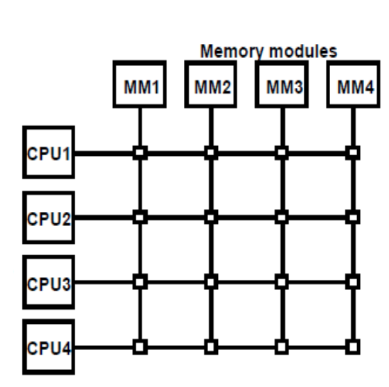
Fig: Crossbar switch
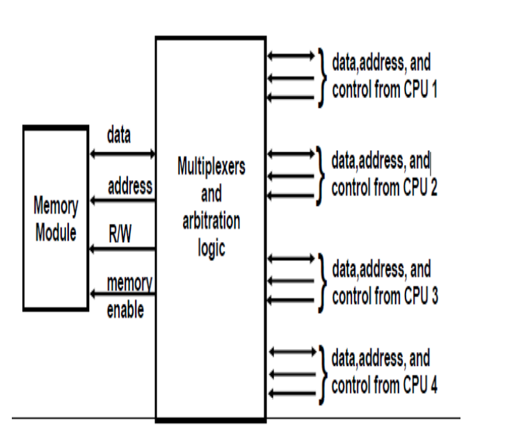
Fig: Block diagram of crossbar switch
Multistage switching network
● A two-input, two-output interchange switch is the most basic component in a multi-stage switching network.
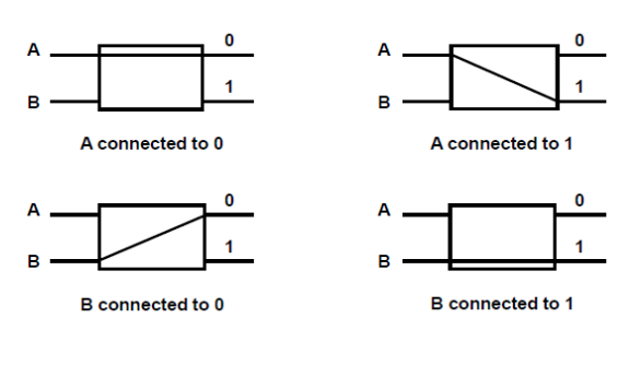
Fig: Interconnection switch
● It is feasible to establish a multistage network using the 2x2 switch as a building element to control communication between several sources and destinations.
○ Consider the binary tree in Fig. Below to see how this is done.
○ Certain request patterns cannot be fulfilled at the same time.
i.e., if P1 000~011, then P2 100~111
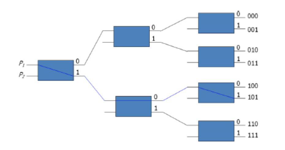
● The omega switching network, depicted in the diagram below, is an example of such a topology.

● Some request patterns can't be linked at the same time. i.e., no two sources can be connected to destination 000 and 001 at the same time.
● Set up the path → transfer the address into memory → transfer the data
Hypercube system
A loosely coupled system built of N=2n processors interconnected in an n-dimensional binary cube is known as a hypercube or binary n-cube multiprocessor structure.
● Each processor is a cube node, which means it contains not just a CPU but also local memory and an I/O interface.
● Each processor address differs by exactly one bit position from each of its n neighbors.
● The hypercube structure for n=1, 2, and 3 is shown in the diagram below.
● From a source node to a destination node, routing messages through an n-cube structure can take anything from one to n links.
● The exclusive-OR of the source node address and the destination node address can be used to create a routing method.
● The message is then delivered along any of the axes, with the resultant binary value containing one bit for each axis on which the two nodes disagree.
● The Intel iPSC computer complex is an example of hypercube architecture.
● Each node contains a CPU, a floating point processor, local memory, and serial communication interface units, and is made up of 128(n=7) microcomputers.
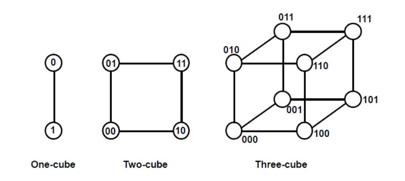
Fig: Hypercube structures for n=1,2,3
Key takeaway
Depending on the number of transfer channels available between the processors and memory in a shared memory system and among the processing elements in a loosely linked system, the interconnection between the components of a multiprocessor system can have varied physical configurations.
To handle many requests to shared resources and resolve multiple contentions, an arbitration system is required. At any given time, only one of the CPU, IOP, or Memory can use the bus.
To simplify the movement of information between its various components, a computer system requires buses. Even in a single-processor system, if the CPU needs to access a memory location, it sends the memory location's address via the address bus. A memory chip is activated when this address is entered. The CPU then sends a red signal over the control bus, which causes the RAM to place the data on the address bus. A memory chip is activated when this address is entered. After that, the CPU sends a read signal on the control bus, and the memory responds by putting the data on the data bus. If any processor in a multiprocessor system needs to read a memory location from common areas, it follows the same procedure.
Data is transferred between the CPUs and memory via buses. Memory buses are what they're called. Data is transferred to and from input and output devices via an I/O bus. The system bus is a bus that connects essential components in a multiprocessor system, such as CPUs, I/Os, and memory. In a multiprocessor system, a processor seeks access to a component over the system bus. If no processor is accessing the bus at that time, it is instantly assigned control of the bus. If the bus is being used by a second processor, that CPU must wait for the bus to be freed. If more than one processor requests the bus's services at the same time, the arbitration mechanism is used to resolve the disagreement. To handle this, a bus controller is installed between the local bus and the system bus.
System bus
● A bus connects the essential components like CPUs, IOPs, and memory.
● A typical System bus has 100 signal lines that are separated into three groups: data, address, and control. There are also power distribution lines to the various components.
Synchronous Bus
● A time slice is used to convey each data item.
● Both the source and destination units are aware of this.
● To synchronize the clocks in the system, a common clock source or a separate clock and synchronization signal is provided on a regular basis.
Asynchronous Bus
The Handshake technique is used to transfer each data item.
● The data-transmitting unit sends out a control signal to indicate the presence of data.
● To confirm receipt of the data, the unit receiving the data reacts with another control signal.
One of the units sends a strobe pulse to the other to signify that data transfer is required.

Fig: IEEE standard 796 multibus signals
Serial Arbitration Procedure
● All processor requests are serviced via an arbitration system based on set priorities. A serial or parallel connection of the unit demanding control of the system bus can be used to establish a hardware bus priority resolving mechanism.
● A Daisy Chain connection of bus arbitration circuits, similar to priority interrupt logic, is used to produce the serial parity resolving approach.
● The priority of the processes connected to the system bus is determined by their position on the priority control line.
● The device with the highest priority is the one nearest to the priority lines. When numerous devices seek access to the bus at the same time, the device with the highest priority is given preference.
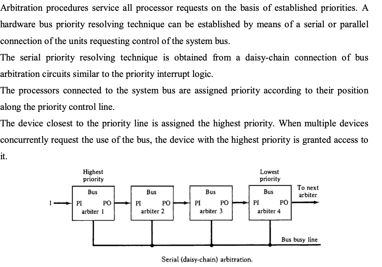
Fig: Serial arbitration procedure
● The processor whose arbiter has a PI = 1 and PO = 0 is the one that is given control of the system bus.
● When a higher priority processor demands the bus, a processor may be in the middle of a bus operation. Before relinquishing control of the bus, the lower priority professor must complete its bus operation.
● When an arbitrator takes charge of a bus, he or she inspects the busy line. If a line is inactive, it signifies that the bus is not being used by any other processor. The arbiter activates the busy line and the bus is taken over by its processor. If the arbiter detects the busy line as active, it signifies that the bus is now being used by another CPU.
● While the lower priority processor that lost control of the bus completes its activity, the arbiter continues to examine the busy line.
● The higher priority arbiter enables the bus busy line when it returns to its inactive state, allowing the appropriate CPU to complete the required bus transfer.
Parallel Arbitration Logic
As indicated in the diagram, the parallel bus arbitration technique employs an external priority encoder and Decoder. Each and every bus and beta In A bus request output line and a bus knowledge input line are included in the parallel scheme. When a CPU requests access to the system bus, each arbiter enables the request line. If the processor's knowledge input line is activated, it takes control of the bus.
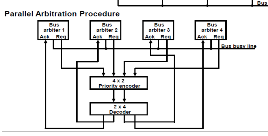
Fig: Parallel arbitration procedure
Dynamic Arbitration
While the system is running, the unit priorities can be changed dynamically.
Time slice - Each CPU receives a fixed length time slice in a round robin method.
Polling - Unit address polling - The address is advanced by the bus controller to identify the requesting unit. When the processor that requires access recognizes the address, the bus busy line is activated, and the bus is then accessed. The polling continues after a few bus cycles by selecting a different processor.
LRU - The least recently used algorithm prioritizes the requesting device that has not utilized the bus for the longest time.
FIFO - Requests for the first come, first served system are fulfilled in the order in which they are received. A queue data structure is maintained by the bus controller in this case.
Rotating Daisy Chain
● Daisy Chain - Priority is given to the unit closest to the bus controller.
● Daisy Chain Rotation – The last device's PO output is connected to the first device's PI. Priority is given to the unit that is closest to the unit that has used the bus the most recently (it becomes the bus controller).
Key takeaway
To handle many requests to shared resources and resolve multiple contentions, an arbitration system is required. At any given time, only one of the CPU, IOP, or Memory can use the bus.
To simplify the movement of information between its various components, a computer system requires buses. Even in a single-processor system, if the CPU needs to access.
● A capability for communication between the multiple processors in a multiprocessor system must be provided.
○ A communication path can be constructed by using a chunk of memory or a set of shared input-output channels.
● A request, a message, or a procedure is structured by the sender processor and placed in the memory mailbox.
○ Bits of status stored in shared memory.
○ The receiving processor has the ability to check the mailbox on a regular basis.
○ This procedure's reaction time can take a long time.
● A more efficient method is for the transmitting CPU to send an interrupt signal straight to the receiving processor.
● A multiprocessor system may have various shared resources in addition to shared memory. A magnetic disk storage unit, for example.
● There must be a mechanism for assigning resources to processors in order to avoid several processors from using shared resources in conflict. That is, the operating system.
● Master-slave configuration, distinct operating system, and distributed operating system are three groups that have been utilized in the design of multiprocessor operating systems.
● In a master-slave configuration, the operating system operations are always executed by one processor, the master.
● Each processor in the independent operating system organization can run the operating system functions it requires. This structure is better suited to loosely linked systems.
● The operating system routines are distributed among the available processors in a distributed operating system structure. Each operating system function, on the other hand, is assigned to only one CPU at a time. A floating operating system is another name for it.
Loosely Coupled System
● Information cannot be passed since there is no shared memory.
● Messages travelling over I/O channels are used to communicate between CPUs.
● One processor initiates communication by invoking a procedure stored in the memory of the processor with which it desires to communicate.
● The interprocessor network's communication efficiency is determined by the communication routing protocol, processor speed, data link speed, and network topology.
● A multiprocessor's instruction set comprises basic instructions for implementing communication and synchronization amongst collaborating processors.
● Interprocess communication is defined as the interchange of data between separate processes. For example, parameters provided to a procedure in a different processor is an example of interprocess communication.
● Control information is utilized to communicate between processors, which is referred to as synchronisation. Synchronization is required to ensure that processes run in the correct order and that mutually exclusive access to shared writable data is maintained.
● Multiprocessor systems typically include a variety of strategies for resource synchronization.
● The hardware implements low-level primitives natively. These primitives are the fundamental methods that enforce mutual exclusion for more complex software systems.
● A number of mutual exclusion hardware techniques have been created.
● The employment of binary semaphore is one of the most prevalent approaches. Using a Semaphore, mutual exclusion can be achieved.
● A well working multiprocessor system must have a mechanism in place to ensure that shared memory and other shared resources are accessed in a timely manner.
● This is required to prevent data from being modified by two or more processors at the same time. Mutual exclusion is the name given to this technique. When a multiprocessor system is in a critical area, mutual exclusion must be given to allow one processor to exclude or shut out other processes from accessing a shared resource.
● A critical section is a program sequence that must finish before another processor can access the same shared resources.
● A semaphore is a binary variable that indicates whether or not a processor is performing a vital section. A semaphore is a software control flag maintained in a memory region accessible by all processors.
● A semaphore is a binary variable that indicates whether or not a processor is performing a vital section.
● The testing and setting of the semaphore is a significant activity in and of itself, and it must be done as a single, indivisible action.
● A test and set instruction combined with a hardware lock mechanism can be used to initialize a semaphore.
● When the semaphore is set to 1, it indicates that a CPU is running a vital program that prevents other processors from accessing shared memory.
● When the semaphore is set to 0, any requesting CPU has access to the shared memory. By convention, processors sharing the same memory segment agree not to utilize it unless the semaphore is set to 0, signalling that memory is available. They also agree to set the semaphore to 1 while working on a critical part and to clear it to 0 when finished.
● The testing and setting of the semaphore is a significant activity in and of itself, and it must be done as a single, indivisible action. If it isn't, two or more processors can concurrently test the semaphore and subsequently set it, allowing them to enter a crucial area at the same time. This action would allow for the simultaneous execution of critical sections, which could result in incorrect control parameter setup and the loss of critical information.
● A semaphore for can be set up with the use of a test and set instruction and a hardware lock mechanism.
● Hardware lock is a signal emitted by the CPU that prevents other processes from using the system bus while it is active. During the execution of the test and set instruction, a semaphore is tested and set, and the lock mechanism is activated.
● TSL SEM will be executed in two memory cycles (the first for reading and the second for writing), as follows:
R ← M[SEM] Test semaphore
M[SEM] ← 1 Set semaphore
Key takeaway
A multiprocessor's instruction set comprises basic instructions for implementing communication and synchronization amongst collaborating processors.
Multiprocessor systems typically include a variety of strategies for resource synchronization.
The hardware implements low-level primitives natively. These primitives are the fundamental methods that enforce mutual exclusion for more complex software systems.
References:
- Computer System Architecture by Morris Mano, Prenticehall, 3rd Edition, (2007)
- Computer Organization by Carl Hamacher, ZvonkoVranesic, SafwatZaky, Tata Mcgraw Hill, 5th Edition, (2011)
- Computer Architecture: A Quantitative Approach by Hennessy, J. L, David A Patterson, and Goldberg, Pearson Education, 4th Edition, (2006)