Unit - 1
Principles of Electro mechanical Energy Conversion
Electromechanical energy conversion is a conversion of mechanical energy into electrical energy (generator) or vice-versa (motor) with the aid of rotary motion (rotary machines) or translatory (linear) motion (linear machines and actuators).
Electrical machines (e.g. Motors & generators), solenoid actuators and electromagnets are generally called electromechanical energy conversion devices.
For energy conversion between electrical and mechanical forms, electromechanical devices are developed. In general, electromechanical energy conversion devices can be divided into three categories:
(1) Transducers (for measurement and control) These devices transform the signals of different forms. Examples are microphones, pickups, and speakers.
(2) Force producing devices (linear motion devices) These type of devices produce forces mostly for linear motion drives, such as relays, solenoids (linear actuators), and electromagnets.
(3) Continuous energy conversion equipment These devices operate in rotating mode. A device would be known as a generator if it converts mechanical energy into electrical energy, or as a motor if it does the other way around (from electrical to mechanical).
Since the permeability of ferromagnetic materials are much larger than the permittivity of dielectric materials, it is more advantageous to use electromagnetic field as the medium for electromechanical energy conversion. As illustrated in the following diagram, an electromechanical system consists of an electrical subsystem (electric circuits such as windings), a magnetic subsystem (magnetic field in the magnetic cores and airgaps), and a mechanical subsystem (mechanically movable parts such as a plunger in a linear actuator and a rotor in a rotating electrical machine). Voltages and currents are used to describe the state of the electrical subsystem and they are governed by the basic circuital laws: Ohm's law, KCL and KVL.
The state of the mechanical subsystem can be described in terms of positions, velocities, and accelerations, and is governed by the Newton's laws. The magnetic subsystem or magnetic field fits between the electrical and mechanical subsystems and acting as a "ferry" in energy transform and conversion. The field quantities such as magnetic flux, flux density, and field strength, are governed by the Maxwell's equations. When coupled with an electric circuit, the magnetic flux interacting with the current in the circuit would produce a force or torque on a mechanically movable part. On the other hand, the movement of the moving part will could variation of the magnetic flux linking the electric circuit and induce an electromotive force (emf) in the circuit. The product of the torque and speed (the mechanical power) equals the active component of the product of the emf and current. Therefore, the electrical energy and the mechanical energy are inter-converted via the magnetic field.
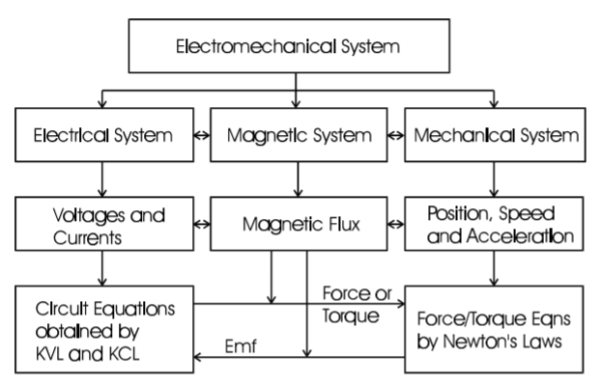
Fig 1. Electro mechanical System Modeling
As we already know that the current through the inductive coil gradually changes from zero to maximum value I, Then, this change is opposed by the self-induced emf produced. The energy is required to overcome this opposition. The value to value of energy stored will be
Let i=instantaneous value of current
E= induced emf at that instance=Ldi/dt
Work done in time dt is
DW=eidt=L  i dt=L i dt
Total work done will be 

The work is stored as the energy of the magnetic field. Therefore, we have
 Joules
Rate of change of stored energy:
As 

Key takeaway
The work is stored as the energy of the magnetic field. Therefore, we have
 Joules
Example
Que) An iron wire ring of 15 cm mean diameter having a cross-section of 90cm2 is wound with 400 turns of wire. Calculate the exciting current required to establish a flux density of 1Wb/m2 if relative permeability of iron is 1000. What is the value of energy stored?
Sol: B=

I=0.94A


Consider a singly excited linear actuator as shown below.
R : winding resistance.
V: terminal voltage applied to the excitation winding
i: excitation winding current
The position of the movable plunger x, and the force acting on the plunger F with the reference direction chosen in the positive direction of the x axis, as shown in the diagram.
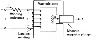
Fig 2 Force on movable magnet plunger
After a time, interval dt the plunger is moved for a distance dx under the action of the force F. The mechanical work done by the force acting on the plunger during this time interval is
DWm=Fdx
The amount of electrical energy that has been transferred into the magnetic field and converted into the mechanical work during this time interval can be calculated by subtracting the power loss dissipated in the winding resistance from the total power fed into the excitation winding as
DWe=dWf+dWm
DWe= vidt-Ri2dt
e= =v-Ri
=v-Ri
DWf= dWe- dWm=eidt-Fdx
=i -Fdx
-Fdx
From the above equation, we know that the energy stored in the magnetic field is a function of the flux linkage of the excitation winding and the position of the plunger. Mathematically, we can also write
DWf( x)=
x)= +
+
From above two equations
i=
F=-
The energy stored in magnetic field is given as
 =
= (
( d
d
For magnetically linear system  =
= 
The force acting on plunger will be F=-
 =
=  i2
i2 
Hence above equation shows the value of force as a partial derivative of stored energy with respect to position of a moving element
Key takeaway
The force acting on plunger will be F=-
 =
=  i2
i2 
The force acting on plunger will be F=-
 =
=  i2
i2 
For torque equation deriving with reference to the above section we can write
DWe=id -Td
-Td
The energy stored in magnetic field is given as
 =
= (
( d
d
i=
T=-
The energy stored in magnetic field is given as
 =
= (
( d
d
For magnetically linear system  =
= 
The Torque acting will be T=-
 =
=  i2
i2 
The diagram below shows a conductor of length l placed in a uniform magnetic field of flux density B. When the conductor moves at a speed v, the induced emf in the conductor can be determined by
e = lv x B
The direction of the emf can be determined by the "right hand rule" for cross products. In a coil of N turns, the induced emf can be calculated by
e=- d
Where  is the flux linkage of the coil and the minus sign indicates that the induced current opposes the variation of the field. It makes no difference whether the variation of the flux linkage is a result of the field variation or coil movement. In practice, it would convenient if we treat the emf as a voltage. The above express can then be rewritten as
e=  =L
=L +i
+i
If the system is magnetically linear, i.e. the self inductance is independent of the current. It should be noted that the self inductance is a function of the displacement x since there is a moving part in the system.
Average conductor force
Fav = Bav l Ic
Bav = avg. Flux density over pole.
l = active conductor length.
Force, F = ZFav = BavlIcZ
T = f.r
T = Bav l IC Zr
r = mean of r gap radius.
Flux/pole


The torque is uniform for given flux/pole and armature current.
Key takeaway
The EMF equation is

The torque is given as

The general principle for force and torque calculation discussed above is equally applicable to multi-excited systems. Consider a doubly excited rotating actuator shown schematically in the diagram below as an example. The differential energy and coenergy functions can be derived as following:
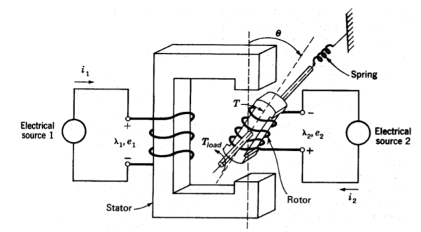
Fig 3 Doubly Excited Actuator
DWf= dWe- dWm
DWe= e1i1dt + e2i2dt
e1= 
e2= 
DWm =T dΘ
Hence,
DWf ( Θ) = i1
  +i2
+i2  -T dΘ
-T dΘ
=  +
+  +
+


Comparing the corresponding differential terms, we obtain


For magnetically linear systems, currents and flux linkages can be related by constant inductances as following


Where L12=L21,  11=L22/
 ,
,  12=
12=  12 =- L12/
 ,
,  22=L11/
 , and
, and  =L11L22-L212. The magnetic energy and coenergy can then be expressed as


Respectively, and it can be shown that they are equal. Therefore, the torque acting on the rotor can be calculated as


Because of the salient (not round) structure of the rotor, the self inductance of the stator is a function of the rotor position and the first term on the right hand side of the above torque expression is nonzero for that dL11/dq 0. Similarly, the second term on the right hand side of the above torque express is nonzero because of the salient structure of the stator. Therefore, these two terms are known as the reluctance torque component. The last term in the torque expression, however, is only related to the relative position of the stator and rotor and is independent of the shape of the stator and rotor poles.
Let us consider the magnetic field is due to electromagnet that is a coil of several no. Turns.
This coil or inductor is carrying current I when it is connected across a battery or voltage source through a switch.
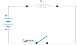
Figure 4. Inductor circuit
Suppose battery voltage is V volts, value of inductor is L Henry, and current I will flow at steady state.
When the switch is ON, a current will flow from zero to its steady value. But due to self- induction a induced voltage appears which is
E = -L dI/dt ---------------------------------------------------------------------(1)
Here E always in the opposite direction of the rate of change of current.
The energy or work done due to this current passing through this inductor is U.As, the current starts from its zero value and flows against the induced emf E, the energy will grow up gradually from zero value to U.
DU = W.dt, where W is the small power and W = – E.I
So, the energy stored in the inductor is given by
DU = W. Dt = -E .I dt = L dI/dt .I dt = LIdI
Now integrate the energy from 0 to its final value.
U =
Again

Where N is the number of turns of the coil, A is the effective cross-sectional area of the coil and l is the effective length of the coil.
Again,
I = H.l/N
Where, H is the magnetizing force, N is the number of turns of the coil and l is the effective length of the coil.

Now putting expression of L and I in equation of U, we get new expression i.e.
U = μoN2 A /l . B.L/ μo N / 2 = B 2 Al/ 2 μo
Key Takeaways:
The energy stored in a magnetic field is equal to the work needed to produce a current through the inductor.
To illustrate the general principle for modeling of an electromechanical system, we still use the doubly excited rotating actuator discussed above as an example. For convenience, we plot it here again. As discussed in the introduction, the mathematical model of an electromechanical system consists of circuit equations for the electrical subsystem and force or torque balance equations for the mechanical subsystem, whereas the interactions between the two subsystems via the magnetic field can be expressed in terms of the emf's and the electromagnetic force or torque. Thus, for the doubly excited rotating actuator, we can write


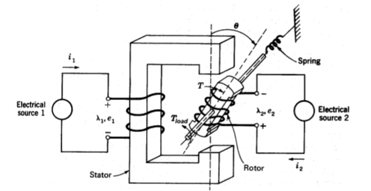
Fig 5 Doubly Excited Actuators


Above is the angular speed of the rotor, Tload the load torque, and J the inertia of the rotor and the mechanical load which is coupled to the rotor shaft. The above equations are nonlinear differential equations which can only be solved numerically. In the format of state equations, the above equations can be rewritten as


Together with the specified initial conditions (the state of the system at time zero in terms of the state variables):
 and
and 
The above state equations can be used to simulate the dynamic performance of the doubly excited rotating actuator.
The basic circuit model for a dc machine is shown below:
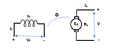
The machine operates in generating mode when the armature current is in the direction of induced emf Ea.
V = Ea – Ia Ra Ea> V
Pmech = Ea Ra = Pelect
The output power,
P0 = VIa
EaIa – VIa = Ia2 Ra
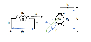
In this mode, the torque of electromagnetic origin is in opposite direction of rotation of armature.
[Pmech]gross = Shaft power = [Pmech]net + Rotational loss.
Motoring Action
As the induced EMF (in the armature due to the field connections) due to residue magnetism destroys the residue magnetism giving negative feedback. So, to overcome this we can either reverse the field connections to armature or the direction of rotation can be reversed. But in large generators with permanent connections, the problem is solved by exciting the filed temporarily from a battery source.
In this mode, the armature current Ia flows opposite to the emf induced i.e. Ea. The basic circuit showing this mode is below:
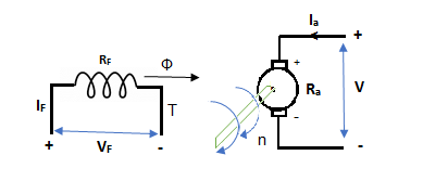
(Ea – Eb) is called as back emf here as it opposes the armature emf.
V = Ea + IaRa
Electrical power connected to mechanical form
Pelec / net = EaIa
Power input, Pi = V Ia
V Ia – EaIa = Ia2Ra = armature copper loss.
The back emf is given as
Eb = 
Average conductor force
Fav = Bav l Ic
Bav = avg. Flux density over pole.
l = active conductor length.
Force, F = ZFav = BavlIcZ
T = f.r
T = Bav l IC Zr
r = mean of r gap radius.
Flux/pole = Bav
= Bav Pl
Pl


The torque is uniform for given flux/pole and armature current.
Q1) Determine torque established by the armature of six pole DC motor having 680 conductors, two paths in parallel, 24mWb flux/pole and armature current 50A?
Sol: 

T= x24x10-3x50x680x(4/2)=259.74 N-m
Q2) A 220V DC Shunt motor runs at 450rpm when armature current is 39A. Calculate speed if the torque is doubled. The armature has a resistance of 0.2 ohm?
Sol: Ta α φIa
Ta1 α φIa1 and Ta2 α φIa2
2= Ia2/39
Ia2=78A
N2/N1=Eb2/Eb1
Eb1=220-(39x0.2)=212.2Volts
Eb2=220-(78x0.2)=204.4Volts
N2/450=204.4/212.2
N2=433.46 rpm
Armature Reactions
When armature of a DC Machine carries current, the distributed armature winding produces its own mmf which is known as armature reaction. The figure is shown below.
The nature of armature reaction in a DC machine is cross magnetizing with its axis along the (90° to main pole).
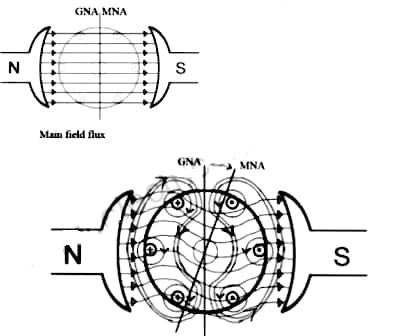
MNA (Magnetic Neutral Axis) It is the axis along which no EMF generated in the armature conductors.
GNA (Geometrical Neutral Axis) It is perpendicular to the field axis.
When DC machine is running the flux due to armature and field winding exists.The armature flux is dominant on the later and hence disturbing the main field flux. This effect is called armature reaction in DC machines.
Q. 1 A 4 pole, 210 V shunt motor has 450 lap wound conductor. It takes 32 A from supply mains and develops output power of 4.5 kW. The field takes 1 A. The armature resistance is 0.09 ohm and flux per pole is 30 mWb. Calculate speed and torque.
Soln. Ia = 32-1 = 31 n
Eb = V – Ia Ra = 210 - (0.09×31) = 207.21 V


N = 920.9 rpm


Q. 2 A 220 V, dc shunt motor has an armature resistance of 0.3 ohm and field resistance of 105 ohm. At no load speed is 1200 rpm and armature current is 2.3 A on application of rated load speed drops to 1120 rpm. Find the current and power input when motor delivers rated load.
Soln. N1 = 1200 rpm Eb1 = 220 – (0.3×2.3) = 219.31 V
N2 = 1120 rpm Eb2 = 220 – 0.3 Ia2


Ia2 = 37.93 A
Line current = Ia2 + Ish = 37.93 + (220/105) = 40 A
Power input = 220 × 40 = 8800 W
Q.3 A 230 V shunt motor runs at 1000 rpm at no load and takes 6A. The total armature resistance is 0.2 ohm and field resistance is 210 ohm. Calculate the speed when loaded and taking 40 A. Assume flux constant.
Soln. 


Q. 4 The armature resistance of a 15 kW, 230 V series motor is 0? 1 ohm, the brush voltage drop is 3 V and series field resistance is 0.05 ohm. The motor takes 60 A speed is 600 rpm. Calculate speed when current is 100 A.
Soln.


Φ1  60
60
Φ2  100
100


N2=350.22 rpm
Q.5 A 230V DC Shunt motor takes 4A at no load when running at 600 rpm. The field resistance is 100 ohm. The resistance of armature at standstill gives a drop of 6V across armature terminals when 10A were passed through it. Find i) Speed at no load (ii) Torque. Normal input of motor is 6kW
Soln
i)Speed 
Ish=  =2.3A
=2.3A
F.L Power=6000
F.L line current=  =26.08A
Ia=26.08-2.3=23.78A
Ra= =0.6Ω
=0.6Ω


N=566.2 rpm
Ii)Torque Ta=
 =
=

References:
1. Chapman, S. J. 1999. Electric Machinery Fundamentals. New York: McGraw-Hill.
2. Clayton, A. E. And N. H. Hancock 1962. Performance and Design of DC Machines. London: ELBS Pitman Edn.
3. Dorf, R. C. 1993. The Electrical Engineering Handbook. Boca Raton, Florida, 33431: CRC Press.
4. Draper, A. 1967. Electric Machines. London: Longman.
5. Elgerd, O. 1982. Electric Energy System Theory: An Introduction. New York: McGraw-Hill.