Unit - 4
Three phase transformers
Three phase transformer
As the supply is in 3-phase so we need this transformer. Its alternating voltage and currents differ in phase by 120 degrees.
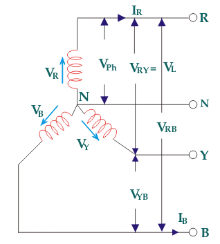
Fig: Three phase Transformer
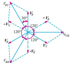
Fig: Line and phase voltage
Construction:
a) Core Type:
The construction of a core type three phase transformer is as shown in the figure. The core consists of three legs or limbs. The core is made up of thin laminated sheets to reduce eddy current losses. Each limb has primary and secondary windings in cylindrical shape (former wound) arranged concentrically. The construction is shown in the figure.
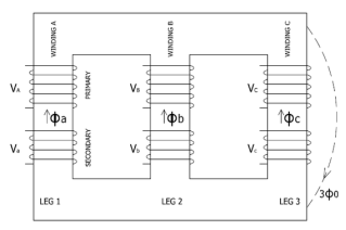
Fig: Core type 3-phase transformer
b) Shell Type:
In a shell type three phase transformer, three phases are more independent than they are in core type. Each phase has its individual magnetic circuit. The construction of shell type three phase transformer is illustrated in the figure at right. The construction is similar to that of three single phase shell type transformers kept on the top of each other.
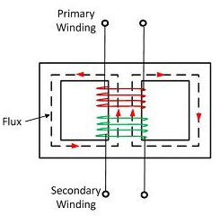
Fig: Shell Type 3-phase Transformer
- The vector for the high voltage winding is taken as the reference vector. Displacement of the vectors of other windings from the reference vector, with anticlockwise rotation, is represented by the use of clock hour figure.
- IS: 2026 (Part 1V)-1977 gives 26 sets of connections star-star, star-delta, and star zigzag, delta-delta, delta star, delta-zigzag, zigzag star, zigzag-delta. Displacement of the low voltage winding vector varies from zero to -330° in steps of -30°, depending on the method of connections.
- Hardly any power system adopts such a large variety of connections. Some of the commonly used connections with phase displacement of 0, -300, -180″ and -330° (clock-hour setting 0, 1, 6 and 11).
- Symbol for the high voltage winding comes first, followed by the symbols of windings in diminishing sequence of voltage. For example a 220/66/11 kV Transformer connected star, star and delta and vectors of 66 and 11 kV windings having phase displacement of 0° and -330° with the reference (220 kV) vector will be represented As Yy0 – Yd11.
- The digits (0, 1, 11 etc) relate to the phase displacement between the HV and LV windings using a clock face notation. The phasor representing the HV winding is taken as reference and set at 12 o’clock. Phase rotation is always anti-clockwise. (International adopted).
- Use the hour indicator as the indicating phase displacement angle. Because there are 12 hours on a clock, and a circle consists out of 360°, each hour represents 30°.Thus 1 = 30°, 2 = 60°, 3 = 90°, 6 = 180° and 12 = 0° or 360°.
- The minute hand is set on 12 o’clock and replaces the line to neutral voltage (sometimes imaginary) of the HV winding. This position is always the reference point.
Example:
- Digit 0 =0° that the LV phasor is in phase with the HV phasor
Digit 1 =30° lagging (LV lags HV with 30°) because rotation is anti-clockwise. - Digit 11 = 330° lagging or 30° leading (LV leads HV with 30°)
- Digit 5 = 150° lagging (LV lags HV with 150°)
- Digit 6 = 180° lagging (LV lags HV with 180°)
- When transformers are operated in parallel it is important that any phase shift is the same through each. Paralleling typically occurs when transformers are located at one site and connected to a common bus bar (banked) or located at different sites with the secondary terminals connected via distribution or transmission circuits consisting of cables and overhead lines.
Phase Shift (Deg) | Connection | ||
0 | Yy0 | Dd0 | Dz0 |
30 lag | Yd1 | Dy1 | Yz1 |
60 lag |
| Dd2 | Dz2 |
120 lag |
| Dd4 | Dz4 |
150 lag | Yd5 | Dy5 | Yz5 |
180 lag | Yy6 | Dd6 | Dz6 |
150 lead | Yd7 | Dy7 | Yz7 |
120 lead |
| Dd8 | Dz8 |
60 lead |
| Dd10 | Dz10 |
30 lead | Yd11 | Dy11 | Yz11 |
|
|
|
|
- The phase-bushings on a three phase transformer are marked either ABC, UVW or 123 (HV-side capital, LV-side small letters). Two winding, three phase transformers can be divided into four main categories
Group | O’clock | TC |
Group I | 0 o’clock, 0° | Delta/delta, star/star |
Group II | 6 o’clock, 180° | Delta/delta, star/star |
Group III | 1 o’clock, -30° | Star/delta, delta/star |
Group IV | 11 o’clock, +30° | Star/delta, delta/star |
Minus indicates LV lagging HV, plus indicates LV leading HV | ||
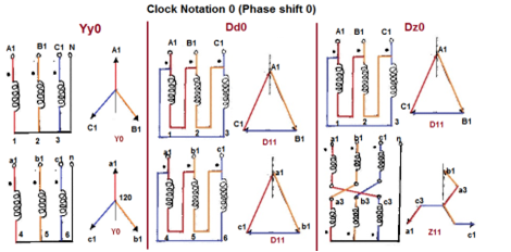
Fig. Clock Notation: 0
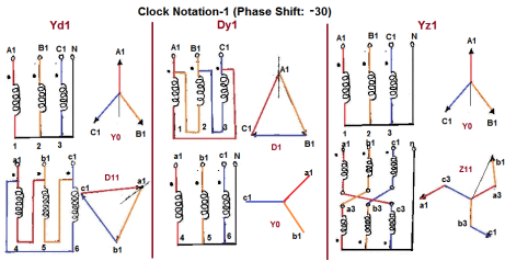
Fig. Clock Notation: 1
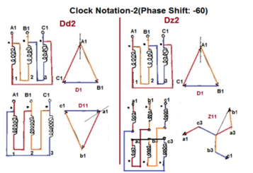
Fig. Clock Notation: 2
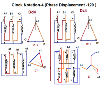
Fig. Clock Notation: 4
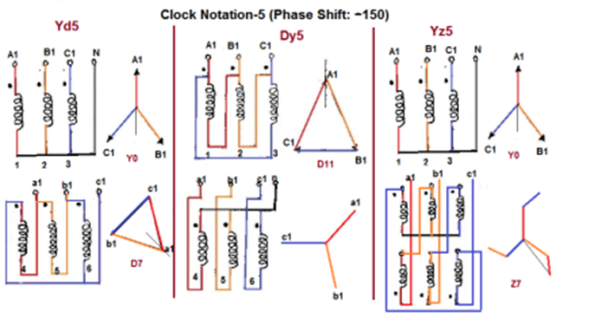
Fig. Clock Notation: 5
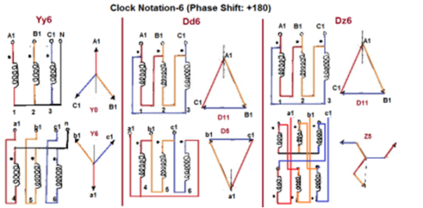
Fig. Clock Notation: 6
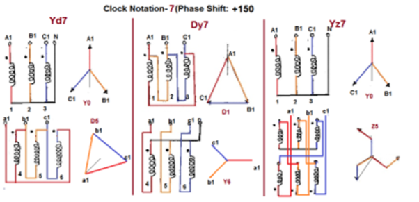
Fig. Clock Notation: 7
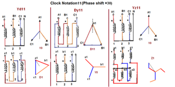
Fig. Clock Notation: 11
Key takeaway
Vector Groups are the IEC method of categorizing the primary and secondary winding configurations of 3-phase transformers. Windings can be connected as delta, star, or interconnected-star (zigzag). Winding polarity is also important, since reversing the connections across a set of windings affects the phase-shift between primary and secondary.
Que 1. A 3-Ø, 50Hz transformer has delta connected primary and star-connected secondary, the line voltage being 20,000 V and 500 V respectively. The secondary has a star connected balanced load at 0.8 lagging p.f. The line current of primary side is 5A. Determine the current in each coil of the primary and secondary line. Also find the output of the transformer?
→ Phase voltage on primary side = 20,000 V
Phase voltage on secondary =  V
V
K = 
Primary phase current = 
Secondary phase current = 
= 
= 200 A
Output =  VLILcosØ
= 
= 138.56 kW
Que 2. A 100 kVA, 3Ø, 50 Hz, 3500/500 V transformer is Δ – connected on the h. V side and Y-connected on the L.V. Side. The resistance of h.V. Winding is 3.5 Ω / phase and that of L.V is 0.02 Ω per phase. Calculate the iron losses of the transformer at normal voltage and frequency if its full load efficiently be 95.1 % at 0.8 p.f.?
→ Full load output = 100 × 0.8 = 80 kW
Input =  kW
kW
Total loss = Input – Output
= 83.2 – 80
= 3200 kW
K = 
K = 
= 
RO2 = R2 + k2R1
= 
= 0.044 Ωs
Full-load secondary phase current I2
= 
= 115.4 A
Total Cu Loss = 3I22RO2
= 3 × 0.044 × (115.4)2
= 1760 W
Iron Loss = Total loss – Cu Loss
= 3200 – 1760
= 1440 W
If only two transformers are used and 3-Ø supply is connected to the primaries as shown below in figure, then three equal 3-Ø voltage will be available at the secondary terminal on no-load.
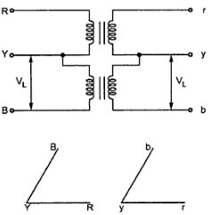
Fig: V-V connection
As one transformer is removed, then the total load carried by V-V bank is not 2/3 of the capacity of Δ-Δ bank but only 57.7% of it. The reduction is of 15% from normal rating.
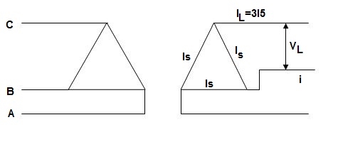
Fig: Closed Δ
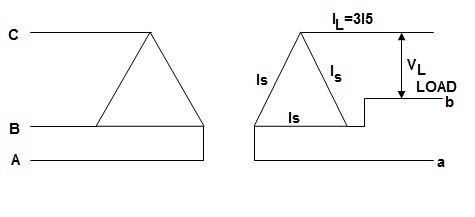
Fig: Open Δ
Now from above figure we can mathematically prove that the capacity is  for this connection.
For closed Δ:
Δ-Δ capacity =  VLIL =
  VL(
VL( IS)
IS)
= 3VLIS
For open Δ:
V-V capacity =  VLIL =
  VLIS
VLIS


Uses: -
1) When three phase loads are too small for the installation of full 3-Ø transformer.
2) When any one of the transformers in Δ-Δ is disabled.
3) When it is found that in near future can increases the change of closing of open delta.
Disadvantage: -
1) The average p.f at which the V-bank operate is less than that of the load.
2) If the load is balanced than also the secondary terminal voltage lend to become unbalanced.
Power supplied by V-V Bank
For V-V connection one transformer operates at p.f cos(30 - Ø) and other at cos(30 + Ø), which means they both does not have same voltage regulation.
P1 = kVA cos(30 - Ø)
P2 = kVA cos(30 + Ø)
1) When Ø = 0˚
Each transformer has p.f = 0.866
2) When Ø = 30˚
One transformer has p.f = 1, other has p.f = 0.866
3) When Ø = 60˚’
In this case only one will supply the entire load as, one has p.f = 0.866 and other has p.f = 0
Key takeaway
1) When three phase loads are too small for the installation of full 3-Ø transformer.
2) When any one of the transformers in Δ-Δ is disabled.
3) When it is found that in near future can increases the change of closing of open delta.
Three phase to 2 phase (Scott connection or T-T connection)
For making 3-Ø to 3-Ø transformation from two transformers we use this connection. It produces two phase powers from three phase source.
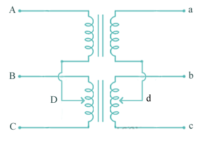
Fig: Scott Connection
- The above figure shows that the centres of one transformer are tap, and has 0.866 tap and is known as Leaser Transformer.
- One ends of both the primary and secondary of Leaser transformer are joined to centre tap on both primary and secondary of main transformer.
- There is one transformer having its centre taps on both primary and secondary and is known as main transformer.
The voltage diagram is shown below
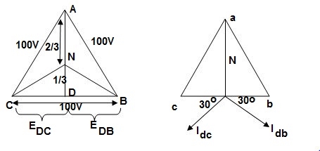
Fig: Voltage and Phase diagram
- EDC and EDB are each 50 V and 180˚ out of phase because coils DB & DC are on same circuit but in opposition.
- EDA is equal to 86.6 V
 and lags behind the voltage across main by 90˚.
 - Idb lags behind voltage Edb by 30˚ and Idc leads Edc by 30˚.
- The teaser transformer and each half of the main transformer all operate at different power factors.
- Full rating of transformer is not utilized. The teaser transformer operate at 0.866 of its rated value and main transformer coil operates at cos 30˚ = 0.866 p.f
Key takeaway
- Used in an electric furnace installation where it is needed to operate two single-phase feeds and draw a balanced load from the three-phase supply.
- Used to supply the single phase loads such as traction power. This helps to keep the load on the three-phase system as nearly balanced as possible.
- Used to link a 3-phase system with a two–phase system with the flow of power in either direction.
Que 1. What should be the kVA rating of each transformer in V-V bank when 3-Ø balanced load is 50 kVA. If a third transformer is connected for operation find % increase in rating?
→ kVA for each transformer has to be 15%
KVA per transformer = 
= 28.75
Δ-Δ bank rating = 28.75 × 3
= 86.75
Increase = 
= 72.5 %
Que 2. A balanced 3-Ø load of 120 kW at 1100V 0.866 lag p.f is supplied from 1500V, 3-Ø main through 1-Ø transformer connected – (i) Δ-Δ (ii) Y-Y
Find current in the windings of each transformer and p.f. at which they operate in each case.
→ (i) Δ-Δ
 VLILcosØ = 120,000
 × 1100 × IL × 0.866 = 120,000
IL = 72.73 A
Secondary line current = 72.73 (= IL)
Secondary phase current =  = 41.99 A
K = 
Primary phase current =  = 20.99 A
(ii) Y-Y connection
 × 1100 × I × 0.866 = 120,000
I = 72.73 A
Secondary phase current = 72.73 A
Primary phase current =  = 41.99 A
Transformer p.f = 86.6 % of 0.866
= 0.75 (lag)
Que 3. Two transformers are required for a Scott connection operating from 410 V 3-Ø supply for supplying two 1-Ø furnaces at 200 V on the two-phase side. If total output is 130 kVA, calculate secondary to primary turn ratio and the winding of each transformer?
→ For main Transformer
Primary voltage = 410 V
Secondary voltage = 200 V

Secondary current =  = 325 A
Primary current = 325 × 
= 153.54 A
For teaser Transformer
Primary volts =  = 355 V
Secondary volts = 200 V

Three phase to 6 phase
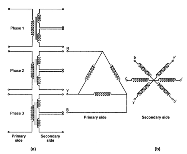
The primary winding is connected in delta whereas its secondary winding is split up into two halves. Thus conversion from 3 phase to six phase can be obtained by having two similar secondary windings for each of the primaries of the three phase transformer. The three phase supply is given to primaries of the three transformers and six phase output can be obtained from the six secondaries as shown. There are many ways of connecting these secondaries. Some of them are i) double delta ii) double star iii) dimetrical. The dimetrical connection is generally used in practice.
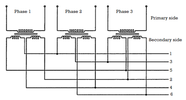
The double delta connection is shown in the Fig
As seen from the Figure below this arrangement of secondaries connections are taken from points 1, 3, 5 and in the second set, the connections are taken from points 2, 4 and 6.
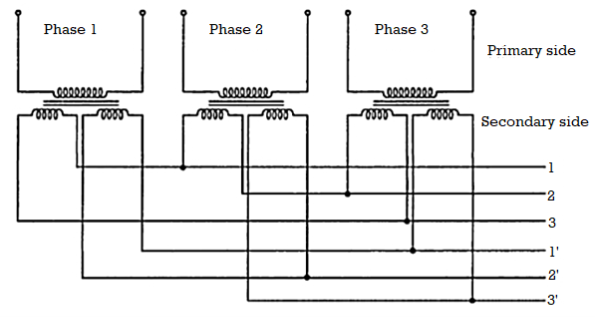
The double star connection for obtaining 6 phase supply is shown in the figure below.
The most commonly used connection is the dimetrical connection for three phase to six phase transformers. It is shown in the Figure below. On each single phase transformer there is only one winding on the secondary side. The two secondary leads are connected to diametrically opposite points on the armature windings of the synchronous converter. The middle points of the secondary windings may be connected together to form a neutral for the three wire circuit. The high voltage or primary windings are either connected in star or delta. But delta connection is generally preferred because of the triple frequency harmonics of voltages which are introduced in star-star connection.
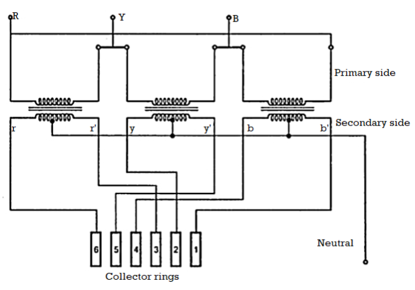
Three to 12 phase connection
Large amounts of a-c power are transformed to dc power by means of electronic rectifiers. A smoother voltage wave form is obtained on the d-c side as the number of phases is increased on the a-c input side. A greater number of phases also results in the reduction of objectionable harmonics in the alternating current. Therefore, 6-phase is preferable to 3-phase for rectification, and, consequently, there are many 6-phase rectifiers and some 12-phase rectifiers in larger installations. There are several methods of connecting transformers for obtaining 3-to-6-phase transformation.
Multiphase, especially a 6-phase and 12-phase system is found to produce less ripple with a higher frequency of ripple in an ac–dc rectifier system. Thus, 6- and 12-phase transformers are designed to feed a multi-pulse rectifier system and the technology has matured. Recently, a 24-phase and 36-phase transformer system has been proposed for supplying a multi pulse rectifier system. The reason of choice for a 6-, 12-, or 24-phase system is that these numbers are multiples of three and designing this type of system is simple and straightforward. However, increasing the number of phases certainly enhances the complexity of the system. None of these designs are available for an odd number of phases, such as 5, 7, 11, etc.,
In this transformer is no-load, the primary input current is very small as compared to the full-load primary current. It is about one percent of the full-load current. When the secondary is loaded, the secondary current is setup. The magnitude and phase of secondary current with respect to the secondary voltage is determined by the characteristics of the load. Secondary current is in phase with secondary voltage if load is non-inductive, it lags behind if load is inductive and it leads ahead if load is capacitive.
Figure below shows Phasor diagram of the proposed transformer connection (star-star). The usual practice is to test the designed motor for a number of operating conditions with a pure sinusoidal supply to ascertain the desired performance of the motor.
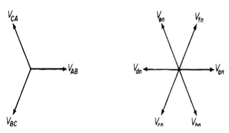
Normally, a no-load test, blocked rotor, and load tests are performed on a motor to determine its parameters. Although the supply used for a multiphase motor drive obtained from a multiphase inverter could have more current ripple, there are control methods available to lower the current distortion even below 1%, based on application and requirement. Hence, the machine parameters obtained by using the pulse width modulated (PWM) supply may not provide the precise true value.
Thus, a pure sinusoidal supply system available from the utility grid is required to feed the motor. This paper proposes a special transformer connection scheme to obtain a balanced Six-phase supply with the input as balanced three phase. The fixed voltage and fixed frequency available grid supply can be transformed to the fixed voltage and fixed frequency six-phase output supply. The output, however, may be made variable by inserting the autotransformer at the input side. The input and output supply can be arranged in the following manner:
1) input star, output star;
2) input star, output polygon;
3) input delta, output star;
4) Input delta, output polygon.
Since input is a three-phase system, the windings are connected in a usual fashion.
It is a transformer in which only one winding is common it both primary and secondary because it has one windy it uses loss copper and is cheaper.
It can be step -up and step down auto-transformer. The circuit for both is shown below.
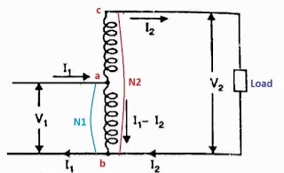
Fig a: Step up auto transformer
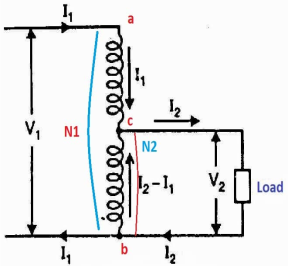
Fig b: Step Down Autotransformer
CB-Primary winding
BA- Secondary windings
Negating iron loss and no-load current-
 =
= =
= =K
=K
The current in AB( ) is vector difference (
 -
- )
)  >
>
An auto transformer when compared to as ordinary 2- winding transformer having same output, given higher efficiency and is smaller in size with superior voltage regulation.
Parallel operation of single phase transformer
If the present transformers are not capable of supplying any amount of additional load which is required, then the parallel connections are used to fulfil the requirement. The basic circuit for parallel transformer is shown below.
The condition required for parallel connections: -
- The primary windings of the transformer should be suitable for supply voltage and frequency.
- The connections w.r.t. Polarity of transformer should be proper.
- The voltage ratings of both primaries and secondaries should be identical.
- In order to avoid circulating current the ratio X/R and percentage impendences should be equal in magnitude.
- The transformer that have different KVA ratings should have equivalent impendences inversely proportional to individual KVA rating.
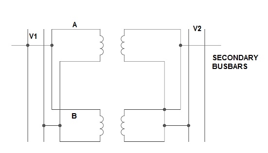
Fig. Parallel Connection of 1-ØTransformer
1) Ideal Case:
Here both the transformers are considered to have same voltage ratio and impedance voltages triangles identical in size and shape.
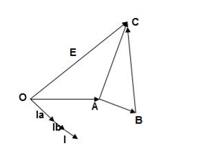
Fig. Phasor for ideal Case
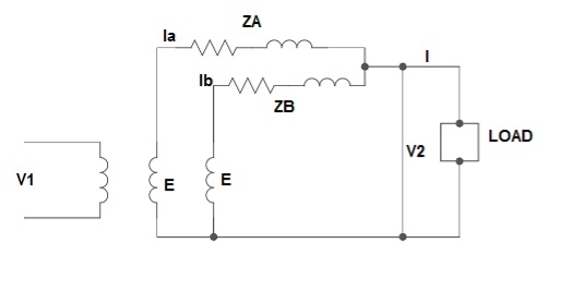
Fig: Ideal Case
I = IA + IB
V2 = E - IAZA
IAZA = IBZB
IA = 
IB = 
E – No load secondary voltage
V2 – Terminal voltage
IA, IB – Currents of each Transformer
2) Equal Voltage Ratio:
Let No-load voltage of each secondary be same E = EA = EB. The change in the secondary is shown below.
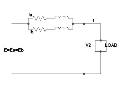
Fig: Equal Voltage Ratio
All values are considered referred to the secondary.
ZA, ZB = impedances of transformer
IA, IB = currents of transformer
V2 = common terminal voltage
IAZA = IBZB = IZAB
ZAB = ZA || ZB
ZA = IZABZA,
IA = 
V2IA = 
V2IB = 
Let V2I × 10-3 = S (Combined Load KVA)
SA = 
SB = 
3) Unequal Voltage Ratios:
Here the no load secondary voltages are unequal.
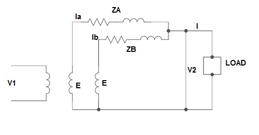
Fig.: Unequal Voltage Ratios
EA, EB = no-load secondary emp
Z1 = load impedance across secondary.
Here circulating current exist as the voltage are unequal (IC).
IC = 
EA = IAZA + V2
EB = IBZB + V2
V2 = IZL = (IA + IB)ZL -----------------(1)
EA = IAZA + (IA + IB)ZL -----------------(2)
EB = IBZB + (IA + IB)ZL -----------------(3)
EA – EB = IAZA – IBZB
IA = 
If ZA and ZB are smaller than ZL.
Substitute IA in equation (3) and solve
IA = 
IB = 
Neglecting ZA ZB in comparison with ZL(ZA + ZB)
We get above equations.
I = IA + IB
I = 
V2 = EA - IAZA and V2 = EB – IBZB
Parallel operation of 3-Ø Transformer
The conditions are same as in case of 1-Ø transformer.
- The voltage ratio must refer to the terminal voltage of primary and secondary.
- The phase displacement between primary and secondary voltages must be same for all transformers.
- The phase sequence must be same.
- All three transformers in 3-Ø transformer bank will be of same construction.
Que 1. What should be the kVA rating of each transformer in V-V bank when 3-Ø balanced load is 50 kVA. If a third transformer is connected for operation find % increase in rating?
→ kVA for each transformer has to be 15%
KVA per transformer = 
= 28.75
Δ-Δ bank rating = 28.75 × 3
= 86.75
Increase = 
= 72.5 %
Que 2. A balanced 3-Ø load of 120 kW at 1100V 0.866 lag p.f is supplied from 1500V, 3-Ø main through 1-Ø transformer connected – (i) Δ-Δ (ii) Y-Y
Find current in the windings of each transformer and p.F at which they operate in each case.
→ (i) Δ-Δ
 VLILcosØ = 120,000
 × 1100 × IL × 0.866 = 120,000
IL = 72.73 A
Secondary line current = 72.73 (= IL)
Secondary phase current =  = 41.99 A
K = 
Primary phase current =  = 20.99 A
(ii) Y-Y connection
 × 1100 × I × 0.866 = 120,000
I = 72.73 A
Secondary phase current = 72.73 A
Primary phase current =  = 41.99 A
Transformer p.f = 86.6 % of 0.866
= 0.75 (lag)
Que 3. Two transformers are required for a Scott connection operating from 410 V 3-Ø supply for supplying two 1-Ø furnaces at 200 V on the two-phase side. If total output is 130 kVA, calculate secondary to primary turn ratio and the winding of each transformer?
→ For main Transformer
Primary voltage = 410 V
Secondary voltage = 200 V

Secondary current =  = 325 A
Primary current = 325 × 
= 153.54 A
For teaser Transformer
Primary volts =  = 355 V
Secondary volts = 200 V

The parallel connection of transformer helps in load sharing. It is impractical and uneconomical to have a single large transformer for heavy and large loads. Hence, it will be a wise decision to connect a number of transformers in parallel.
- In substations, the total load required may be supplied by an appropriate number of the transformer of standard size. As a result, this reduces the spare capacity of the substation.
- If the transformers are connected in parallel, so there will be scope in future, for expansion of a substation to supply a load beyond the capacity of the transformer already installed.
- If there will be any breakdown of a transformer in a system of transformers connected in parallel, there will be no interruption of power supply, for essential services.
- If any of the transformers from the system is taken out of service for its maintenance and inspection, the continuity of the supply will not get disturbed.
- Various conditions that must be fulfilled for the successful parallel operation of transformers:
- Same voltage Ratio & Turns Ratio
- Same Percentage Impedance and X/R ratio.
- Identical Position of Tap changer.
- Same KVA ratings.
- Same Phase angle shift (vector group are same).
- Same Frequency rating.
- Same Polarity.
- Same Phase sequence.
It is known that though secondary is open, the transformer draws current from supply, when primary is excited by rated voltage. This current is not load current and is basically required to produce core flux. But due to non-linearities of core material such as hysteresis and saturation, the no load current is not sinusoidal in nature. Let us study the effect of hysteresis and saturation on the waveform of noload current which is also called exciting current.
Let V1 be the rated voltage applied to primary. The resistive drop Io R1 is negligible. The applied voltage and induced e.m.f. Are sinusoidal in nature. Hence flux in the core also must be sinusoidal. The flux must lag the applied voltage by 90o.
The no load current waveform can be obtained graphically from the hysteresis curve (Φ- Io curve) as shown in the Fig.
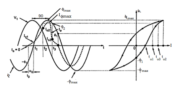
In the steady state, the flux undergoes a cycle of magnetisation and demagnetisation due to sinusoidal voltage V1 and traces a hysteresis loop as shown in the Fig. 1. Consider the various instants. At t =to, Φ = - Φ1 and no load current Io is zero. At t = t1 , flux is zero and Io = Io1. When Φ = - Φ1 at t = t2, Io =Io1. When Φ = Φ2 at t = t2, Io = Io2. Now Φ2 value occurs twice while Φ increasing and decreasing. But due to hysteresis at t = t3, though Φ = Φ2, Io = Io3. So Io3 Io2 through flux is Φ2. When flux is maximum Φmax, the current Io is also at its maximum Iomax. The current Io again becomes zero at Φ =Φ1.
The negative half will be symmetrical to positive half of Io as hysteresis loop is also symmetrical. It can be seen that the Io waveform is non sinusoidal and having some peaks. But it is odd symmetrical i.e. current and flux achieve their maxima simultaneously, but current zeros are advanced with respect to flux.
Hence no load current has fundamental and odd harmonics. The strongest is the third harmonic which is about 40% of fundamental. And Io leads flux Φ by a small angle α0. Due to α0, Io has two components Ic and Im as discussed earlier. This phase shift of α0 is caused due to hysteresis nature Φ - Io curve.
Current inrush phenomenon (Switching transient)
In the steady state operation, both V1 and Φ are sinusoidal and Φ lags V1 by 90° as shown in the Figure. When the primary voltage V1 is switched on to the transformer, the core flux and the exciting current undergo a transient before achieving the steady state. They pass through a transient period. The effect of transient is severe when voltage wave pass through origin.
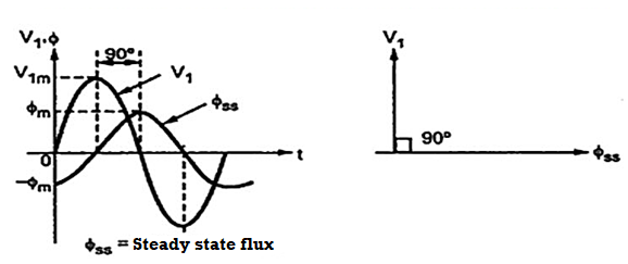
In the inductive circuit flux can start with zero value. But the steady state value of flux at start is -Φm , as shown in the Figure above, at t = 0. Thus during transients a transient flux called off-set flux, Φt = Φm originates such that at t = 0, Φt +Φss is zero at the instant of switching. This transient flux Φt then decays according to circuit constants i.e. ratio L/R. This ratio is generally very small for transformers.
Thus during transients, the total flux goes through a maximum value of 2Φm. Such effect is called doubling effect. This is shown in the Figure below.
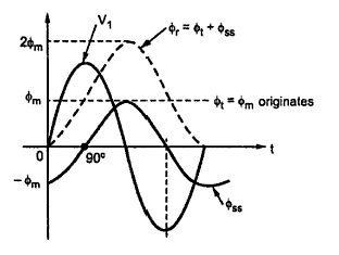
Fig Doubling Effect
Due to the doubling effect, core flux achieves a value of 2Φm due to which transformer draws a large exciting current. This is due to the fact that core goes into deep saturation region of magnetisation. Such a large exiting current can be as large as 100 times the normal exiting current. To withstand electromagnetic forces developed due to large current, the windings of transformer must be strongly braced. This large current drawn during transient is called inrush phenomenon.
Practically initial core flux cannot be zero due to the residual flux Φ'r present, due to retentively property of core. The transient resultant flux goes through Φr = Φ'r + 2Φm and there is heavy inrush current in practice. The effect of transient is even severe in practice. Such high transient current gradually decreases and finally acquires a steady state. It can last for several seconds. The transient flux Φt and exciting current both are unidirectional during transients. In steady state, exciting current becomes sinusoidal.
Harmonics in transformers cause an increase in the iron and copper losses. Voltage distortion increase losses due to hysteresis and eddy currents and causes overstressing of the insulation material used. The primary effect of power line harmonics in transformer is, thus the additional heat generated. Other problems include possible resonance between the transformer inductance and the system capacitance, thermal fatigue due to temperature cycling and possible core vibrations.
As the name suggests this transformer can be made by adding one additional winding. The main use of this type of transformer is for interconnections with the transmission line at various voltages, for measuring voltages of an H.V side transformer, synchronous condensers can be connected to this winding to inject reactive power in system for voltage control. Below is shown the figure which explains how the tertiary winding can be used for stabilization.

Figure: Tertiary winding for stabilization
The unbalanced load cab be divided into three phase sets i.e. positive, negative and zero sequence component. The star-star connection unbalanced load provides high reactance between line and neutral. The zero-sequence current component on secondary side cannot be balanced by primary current and hence magnetic flux is developed on the secondary side. Then the delta connected tertiary allows the circulation of zero-sequence current in it, as shown in the above figure. The equivalent circuit of the three winding transformer is shown below. There are three terminals primary (1), secondary (2), and tertiary (3) and one common terminal, neglecting the exciting current.
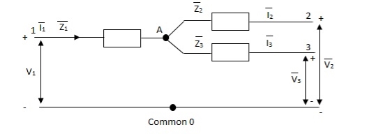
Figure: Single phase equivalent circuit of three winding transformer
The impedance can be calculated by the short circuit test. If  is the short circuit impedance of winding 1 and 2 with winding 3 open, then we can write
 =
=  +
+


The above three equations can also be written as


The core loss, magnetizing loss and turn ratio can be determined by open circuit test on any one of the three windings.
References:
1. A. E. Fitzgerald and C. Kingsley, "Electric Machinery”, McGraw Hill Education,2013.
2. M. G. Say, “Performance and design of AC machines”, CBS Publishers,2002.
3. P. S. Bimbhra, “Electrical Machinery”, Khanna Publishers,2011.
4. I. J. Nagrath and D. P. Kothari, “Electric Machines”, McGraw Hill Education,2010.
5. A. S. Langsdorf, “Alternating current machines”, McGraw Hill Education,1984.
6. P. C. Sen, “Principles of Electric Machines and Power Electronics”, John Wiley & Sons,2007.