Unit - 5
Waves and Applications
According to Ampere’s circuit law the line integral of magnetic field around a closed path is equal to the current enclosed by the path.
 .
.  = I enclosed ---------------------------------------------------------(1)
Replacing current by the surface integral of conduction current density  over an area bounded by the path of integration of
  we get
 .
.  =
=  .dS ---------------------------------------------------------------(2)
Above expression can be made further general by adding displacement current density to conduction current density as follows
 .
.  =
=  +
+  /
/  t . d
t . d -------------------------------------------------(3)
Eq(3) is called the Maxwell equation.
Key Takeaways:
Maxwell's equations are partial differential equations. They link the spatial and temporal rates of change of electric and magnetic fields, and they show how these rates of change are related to the sources of the fields.
- First law: whenever flux linkage with the coil changes an emf is induced in that conductor
- Second law: the magnitude of induced emf is equal to the rate of change of flux linkage
Explanation: suppose a coil has n turns and flux through it change from initial value of Ø1 to Ø2 in line t sec
Initial flux linkage = N Ø
Final flux linkage = NØ2
 Induced emfe =
Putting the above equation in differential form
e = rate of change of flux linkage

The direction of this induced emf is given by lenis law which states the polarity of induced emf is always such that it tends to set up a current which flow in such a direction so as to oppose the cause that produces it.

We all know that when an electrical conductor is introduced into a magnetic field, due to its dynamic interaction with the magnetic field, emf is induced in it. This emf is known as induced emf. In this article, we will learn about motional emf where emf is induced in a moving electric conductor in the presence of a magnetic field.
Consider a straight conductor PQ as shown in the figure, moving in the rectangular loop PQRS in a uniform and time-independent magnetic field B, perpendicular to the plane of the system.
Let us suppose the motion of rod to be uniform at a constant velocity of v m/sec and the surface to be frictionless.
Thus, the rectangle PQRS forms a closed circuit enclosing a varying area due to the motion of the rod PQ.
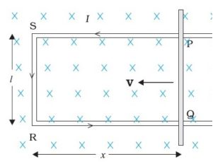
The magnetic flux ΦB enclosed by the loop PQRS can be given as
ΦB = Blx
Where, RQ = x and RS = l, Since the conductor is moving, x is changing with time. Thus, the rate of change of flux ΦB will induce an emf, which is given by:
ϵ =−dϕB/dt=−d(Blx)/dt=−Bldx/dt=Blv
Where, the speed of conductor (PQ), v = -dx/dt and is the formula of induced emf. This induced emf due to the motion of an electric conductor in the presence of the magnetic field is called motional emf. Thus, emf can be induced in two major ways:
Due to the motion of a conductor in the presence of a magnetic field.
Due to the change in the magnetic flux enclosed by the circuit.
This concept of motional emf can be explained with the help of the concept of Lorentz force acting on free charge carriers of the conductor. Let us consider any arbitrary charge q in the conductor PQ. As the rod moves with a constant speed v, the charge is also moving with a speed v in the presence of magnetic field B. The Lorentz force on this charge is given by:
F = qvB
The work done in moving the charge from P to Q can be given by,
W = QBvl
Since, emf is defined as the work done per unit charge,
∈ = wq=Bvl
Displacement Current: Derivation & Its Properties
In electromagnetic theory, the phenomenon of the magnetic field can be explained concerning a change in the electric field. The magnetic field is produced in the surroundings of the electric current (conduction current). Since the electric current might be in the steady-state or varying state. The concept displacement current depends on the variation of time of the electric field E, developed by the British physicist James Clerk Maxwell in the 19th century. He proved that the displacement current is another kind of current, proportional to the rate of change of electric fields and also explained mathematically. Let’s discuss the displacement current formula and necessity in this article.
What is the Displacement Current?
The sort of current created as a result of the rate of electric displacement field D is known as displacement current. It's a time-varying quantity that Maxwell's equations introduce. It's explained in terms of electric current density units. The law of Ampere circuits introduces it.
Ampere is the SI unit for displacement current (Amp). This dimension can be measured in length units, which can be maximum, minimum, or equivalent to the actual distance travelled from start to finish.
Derivation
Consider the fundamental circuit that gives the displacement current in a capacitor to understand the displacement current formula, dimensions, and derivation of displacement current.
Consider a parallel plate capacitor with a power supply requirement. When power is applied to the capacitor, it begins to charge and there is no current flow at first. The capacitor charges continually and builds above the plates as time passes. A change in the electric field between the plates during the charging of a capacitor over time causes the displacement current.
From the given circuit, consider the area of the parallel plate capacitor = S
Displacement current = Id
Jd = displacement current density
d= €E ie., related to electric field E
€ = permittivity of the medium between the plates of a capacitor
The displacement current formula of a capacitor is given as,
Id= Jd × S = S [dD / dt]
Since Jd = dD/dt
The displacement current will have the same unit and effect on the magnetic field as the conduction current, according to Maxwell's equation.
▽×H=J+Jd
Where,
H = magnetic field B as B=μH
μ = permeability of the medium in between the plates of a capacitor
J = conducting current density.
Jd =displacement current density.
As we know that ▽(▽×H) =0 and ▽. J=−∂ρ/∂t=−▽(∂D/∂t)
By using Gauss’s law that is ▽. D=ρ
Here, ρ = electric charge density.
Hence, we can conclude that, Jd=∂D/∂t displacement current density and it is necessary to balance RHS with LHS of the equation.
Properties
The following are the properties of displacement current: • It is a vector quantity that obeys the continuity property in a closed path. • It varies with the rate of change of current in an electric density field.
• When the current in a wire's electric field is constant, it gives zero magnitudes.
• An electric field's fluctuating time is a factor.
• It had a positive, negative, or zero magnitude with both direction and magnitude.
• Regardless of the path, the length of this can be taken as the shortest distance between the starting and ending points.
• It can be measured in length units.
• It has a minimum, maximum, or equivalent magnitude of displacement to the actual distance from the spot for a certain period.
• It is dependent on the presence of an electromagnetic field.
• When the starting and finishing points are the same, it returns zero.
The static electric field  exist without a magnetic field
  demonstrated by a capacitor with static charge Q.
Similarly, a conductor with constant current I has magnetic field  in absence of an electric field
  .
.
But in time varying fields  cannot exist without each other.
Maxwell’s equations are nothing but set of four expressions derived from Ampere’s circuit law, Farady’s law, Gauss’s law for electric field and Gauss’s law for magnetic field.
- Maxwell’s equation derived from Faradays law:
According to the concept from electrostatic field the work done over a closed path or closed contour that is stating point same as terminating point is always zero.
Mathematically it can be represented as
 -----------------------(1)
The above equation is called integral form of Maxwell’s equation derived from Faradays law of static field.
Using Stroke’s theorem converting close line integral into surface integral we get


But  cannot be zero which means
  = 0.
= 0.
Point form of Maxwell’s equation derived from differential form.
- Maxwell’s equation derived from Ampere’s Circuital Law:
According to the basic concept of magnetostatics an Amper’s circuital law states that the line integral of magnetic field intensity  around closed path is exactly equal to direct current enclosed by that path.
Mathematically 
Now the current enclosed is equal to the product of current density normal to the closed path and area of closed path. Hence, we get
 where
where
Hence evaluating the above equations, we get

The above expression is integral form of Maxwell’s equation from Ampere circuital law for static field.
Now by applying Stoke’s theorem LHS of the equation can be converted into surface integral

Hence, we get

- Maxwell’s equation derived from Gauss Law:
According to Gauss law of electrostatic fields the electric flux through any closed surface is equal to the total charge enclosed by that surface. Mathematically we can write
 1
1
The most common form to represent Gauss law mathematically is volume charge density Pv hence, we can write
 ----2
----2
The above equation is called integral form of Maxwell’s equation derived from Gauss Law.
To establish the relationship between  and Pv converting closed surface integral into volume integral using divergence theorem as
 ----3
----3
Comparing 2 and 3 we get

- Maxwell’s equation derived from Gauss Law for Magnetostatic field.
According to Gauss law for magneto static field the magnetic flux cannot reside in closed surface due to non-existence of single magnetic pole.
Mathematically we can write

The above equation is called Integral form of Maxwell’s equation derived from Gauss law for static magnetic field.
Now using divergence theorem we can write


Now dV cannot be zero that means  .
.
Key takeaway
Name of law | Differential form | Integral form |
Gauss’s law |  |  |
Faraday’s law |  |  |
Gauss’s law of magnetics |  |  |
Ampere’s law |  |  |
The imperfect conductors are called as lossy dielectrics. They are basically poor insulators where the free charges conduct to some extent. Here  which means the conductor is imperfect as well as the dielectric.
The equation for propagation constant will now be


We can calculate the values of  by substituting values of
  . The propagation constant for lossy medium is defined by the above equation. The value of intrinsic impedance for this medium is given as
η =
Since 
η = |η| ohms
ohms
Because of the complex quantity, η is represented in polar form as shown in the above equation where Өn is the phase angle difference between electric and magnetic fields. Thus, in lossy dielectric medium there exist a phase difference between the electric and magnetic fields.
The intrinsic impedance can be expressed as
η = 
=  /
/  (1 + (σ/
  )]
)]
η = (√ (µ/ є)) (1 / √ (1 – j (σ/  )) ohms
And the angle Өn is given as
Өn = ½ [(π/2) – tan-1 ( / σ)]
/ σ)]
This angle depends on the frequency of the signal as well as properties of the lossy dielectric medium. Then, w becomes very small for a low frequency signal. Thus, the phase angle is given as
Өn = (π/4)
For very high frequency signal, w becomes very large then,
Өn = 0
So, the range of Өn of a lossy dielectric for complete frequency range is 0 Өn (π/4)
Reflection by perfect dielectric- normal incidence
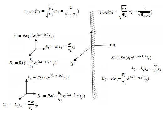
Fig: A uniform plane wave normally incident upon a dielectric interface separating two different materials has part of its power reflected and parts transmitted
The perfect conductor with a lossless dielectric of permittivity  and permeability
  , as in Figure with a uniform plane wave normally incident from a medium
  with permittivity and permeability
  . In addition to the incident and reflected fields for z 0.
The unknown quantities  and
and  can be found from the boundary conditions of continuity tangential E and H at z=0,


From which we find reflection R and transmission field T field co-efficients as


Where 1 + R = T.
In an electromagnetic wave, electric and magnetic field vectors are perpendicular to each other and at the same time are perpendicular to the direction of propagation of the wave. This nature of electromagnetic wave is known as Transverse nature.
Maxwell proved that both the electric and magnetic fields are perpendicular to each other in the direction of wave propagation. He considered an electromagnetic wave propagating along positive x-axis. When a rectangular parallelepiped was placed parallel to the three co-ordinate axis, the electric and magnetic fields propagate sinusoidal with the x-axis and are independent of y and z-axis.
A wave in which the values of variable are constant in a plane perpendicular to the direction of propagation of the wave is called plane wave. These planes may also termed as wave fronts.
Solutions of Maxwell’s Equations - Uniform Plane Waves
The sources of time varying electromagnetic fields are time varying charges and currents, whether man-made or naturally occurring. However, examination of Maxwell’s equations shows that, even in empty space (with no sources), and fields cause each other. This means that, although these fields must originate in source regions, they can propagate through source-free regions. Because solutions in source regions are very hard to obtain, let us consider what kind of fields can exist in source-free regions.


These equations are still very complicated (4 different partial derivatives). Let’s try to find simple solutions. We do this by making assumptions. After finding simplest solutions, we:
(i) Find what kind of source would generate this type of field (waves).
(ii) Show that these simple solutions are useful approximations to real electromagnetic waves.
Assumption for Solution:
Can we find a solution such that:
1.) No variation exists in x and y directions.
2.)  or
or  also is oriented along one of the axes.
Ampere’s Law becomes:

Or, with our assumptions:

Compare for transmission line:

In a similar manner,
 ………….(1)
Faraday’s Law becomes:
 ………….(2)
Thus, if  is only in the
  direction, then is only in the .If we differentiate (2) with respect to z, we get:
Substitute from (2), 
We get 
This is called the wave equation.
Compare for transmission line: (same).

We will assume dielectric media; lossless:

Dimensional analysis:


In the units we are using:


By exactly the same method, we also get:


For example, the same equation is true for  and
and  . Thus,
 and
and  must have the same type of functional dependence. This wave equation still has many possible solutions. In fact, it can be shown by direct substitution that

Are the solutions

t is important to note that f1 and f2 can be any function.
The field we find directly from the equation:

Suppose
 …………(3)
Differentiate (3) with respect to z
 …………(4)
Integrate with respect to time
 …………(5)

This leads to a new quantity that relates the electric and magnetic fields:


Rewriting:
Units of  =
=  =
= = Ω
= Ω
 = Impedance of free space =
  =377 Ω
 = impedance of a lossless dielectric =
  =
= =
=
Note that  and
and  are in time phase and space quadrature
The directions of the vectors are such that:


This vector  , always points in the direction of propagation. These types of waves are called Uniform Plane Electromagnetic Waves.
“Plane” refers to the fact that, at any instant in time, the surfaces of constant phase are planes (here, constant).
“Uniform” means no variation in transverse direction. The wave derived here is one oscillating at a single frequency. The frequency is determined by the source. If the source has multiple frequencies, so will the wave. In communications, modulating a carrier wave results in multiple frequencies. But before we can study such fields, we must thoroughly understand single frequency sinusoidal waves.
Key Takeaways
- A wave in which the values of variable are constant in a plane perpendicular to the direction of propagation of the wave is called plane wave. These planes may also be termed as wave fronts.
- This vector
 , always points in the direction of propagation. These types of waves are called Uniform Plane Electromagnetic Waves.
A uniform plane wave with x-directed electric field is normally incident upon a perfectly conducting plane at z =0, as shown in Figure. The presence of the boundary gives rise to a reflected wave that propagates in the -z direction. There are no fields within the perfect conductor. The known incident fields traveling in the +z direction can be written as


While the reflected fields propagating in the -z direction are similarly


Where in the lossless free space

The minus sign difference in the spatial exponential phase factors of (1) and (2) as the waves are traveling in opposite directions. The amplitude of incident and reflected magnetic fields are given by the ratio of electric field amplitude to the wave impedance.
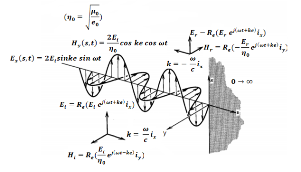
The negative sign in front of the reflected magnetic field for the wave in the -z direction arises because the power flow S, = E, x H, in the reflected wave must also be in the -z direction. The total electric and magnetic fields are just the sum of the incident and reflected fields. The only unknown parameter E, can be evaluated from the boundary condition at z =0 where the tangential component of E must be continuous and thus zero along the perfect conductor:
The total fields are the sum of incident and reflected fields

=
=

=
=
The electric and magnetic fields are 90* out of phase with each other both in time and space.
Poynting theorem states that the net power flowing out of a given volume V is equal to the time rate of decrease of stored electromagnetic energy in that volume decreased by the conduction losses is the total power leaving the volume = rate of decrease of stored electromagnetic energy ohmic power dissipated due to motion of charge.
Proof:
The energy density carried by the electromagnetic wave can be calculated using Maxwell's equations


 (5)
(5)
 (6)
(6)
 (7)
(7)


=

So from equation (vii) 
 (viii)
Integrating equation (viii) over a volume V enclosed by a surface S

Or 
As 
Or 
Or 
Or 
That is the Total power leaving the volume = rate of decrease of stored e.m.f energy - ohmic power dissipated due to charge motion
This equation (ix) represents the poynting theorem according to which the net power flowing out of a given volume is equal to the rate of decrease of stored electromagnetic energy in that volume minus the conduction losses.
When incident wave is normal”
Consider the case of a plane wave travelling in the x direction incident on a boundary parallel to the plane x=0 as shown in figure 6.7. Let  be the dielectric field strength of the incident wave striking the boundary,
  be the electric field strength of the transmitted wave propagated in the second medium.
Similarly let 
 represents magnetic field.
Again let  be the constants of the first medium and
  those of the second then the following relation will hold


The continuity of tangential component of  required that

And, 


Therefore for electric field reflection coefficient

And transmission coefficient


Similarly for magnetic field
 (6.14)
 (6.15)
The permeability of all known perfect dielectrics that is insulators do not differ appreciable from that of free space so that  Inserting this relation in the above equation we have for electric field


Similarly for magnetic field


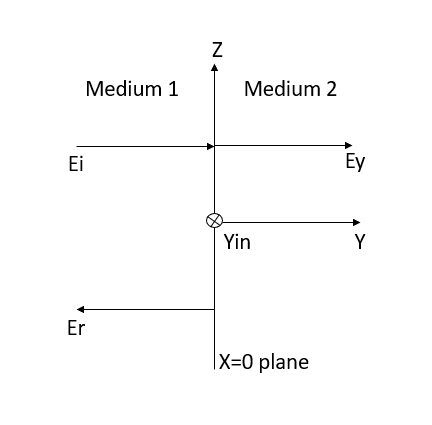
Figure: Reflection by a perfect dielectric, normal incidence.
A transmission line is a means of transfer of information from one point to another. Usually, it consists of two conductors. It is used to connect a source to a load. The source may be a transmitter and the load may be a receiver.
The performance of transmission line depends on the parameters of the line. The transmission line has mainly four parameters, resistance, inductance, capacitance and shunt conductance. These parameters are uniformly distributed along the line. Hence, it is also called the distributed parameter of the transmission line.
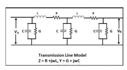
Figure. Transmission Line
The inductance and resistance form series impedance whereas the capacitance and conductance form the shunt admittance.
Line inductance – The current flow in the transmission line induces the magnetic flux. When the current in the transmission line changes, the magnetic flux also varies due to which emf induces in the circuit. The magnitude of inducing emf depends on the rate of change of flux. Emf produces in the transmission line resist the flow of current in the conductor, and this parameter is known as the inductance of the line.
Line capacitance – In the transmission lines, air acts as a dielectric medium. This dielectric medium constitutes the capacitor between the conductors, which store the electrical energy, or increase the capacitance of the line. The capacitance of the conductor is defined as the present of charge per unit of potential difference.
Capacitance is negligible in short transmission lines whereas in long transmission; it is the most important parameter. It affects the efficiency, voltage regulation, power factor and stability of the system.
Shunt conductance – Air act as a dielectric medium between the conductors. When the alternating voltage applies in a conductor, some current flow in the dielectric medium because of dielectric imperfections. Such current is called leakage current. Leakage current depends on the atmospheric condition and pollution like moisture and surface deposits.
Shunt conductance is defined as the flow of leakage current between the conductors. It is distributed uniformly along the whole length of the line. The symbol Y represented it, and it is measured in Siemens.
The Smith Chart is a tool for visualizing the impedance of a transmission line and antenna system as a function of frequency. Smith Charts can be used to increase understanding of transmission lines and how they behave from an impedance viewpoint.
Smith Charts are also extremely helpful for impedance matching. The Smith Chart is used to display a real antenna's impedance when measured on a Vector Network Analyzer (VNA).
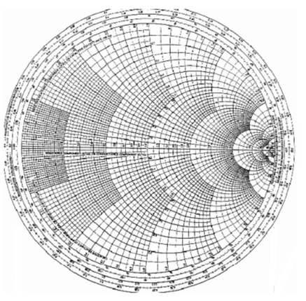
Basic smith chart
The Smith Chart displays the complex reflection coefficient, in polar form, for an arbitrary impedance
The complex reflection coefficient () for an impedance ZL attached to a transmission line with characteristic impedance Z0 is given by

Let us assume Z0 is 50 Ohms, which is often. The complex reflection coefficient, or, must have a magnitude between 0 and 1.
As such, the set of all possible values for must lie within the unit circle:
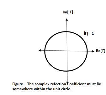
In Figure, plotting the set of all values for the complex reflection coefficient, along the real and imaginary axis. The center of the Smith Chart is the point where the reflection coefficient is zero. That is, this is the only point on the smith chart where no power is reflected by the load impedance.
The outer ring of the Smith Chart is where the magnitude of is equal to 1. This is the black circle in Figure 1. Along this curve, all of the power is reflected by the load impedance.
Normalized Load Impedance
To make the Smith Chart more general and independent of the characteristic impedance Z0 of the transmission line, we will normalize the load impedance ZL by Z0 for all future plots:
 ………….[1]
Equation [1] doesn't affect the reflection coefficient tow. It is just a convention that is used everywhere.
Constant Resistance Circles
For a given normalized load impedance zL, we can determine and plot it on the Smith Chart. Now, suppose we have the normalized load impedance given by:

In equation [2], Y is any real number. What would the curve corresponding to equation [2] look like if we plotted it on the Smith Chart for all values of Y? That is, if we plotted z1 = 1 + 0*i, and z1 = 1 + 10*i, z1 = 1 - 5*i, z1 = 1 - .333*i, .... And any possible value for Y that you could think of, what is the resulting curve? The answer is shown in Figure below:
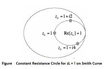
In this Figure, the outer blue ring represents the boundary of the smith chart. The black curve is a constant resistance circle: this is where all values of z1 = 1 + i*Y will lie on. Several points are plotted along this curve, z1 = 1, z1 = 1 + i*2, and zL = 1 - i*4. Suppose we want to know what the curve z2 = 0.3 + i*Y looks like on the Smith Chart. The result is shown in Figure below:
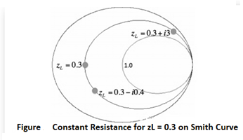
In this Figure, the black ring represents the set of all impedances where the real part of z2 equals 0.3. A few points along the circle are plotted. We've left the resistance circle of 1.0 in red on the Smith Chart. These circles are called constant resistance curves. The real part of the load impedance is constant along each of these curves. Now add several values for the constant resistance, as shown in Figure below:
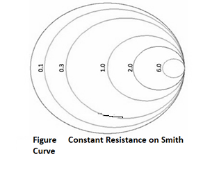
In above Figure, the zL=0.1 resistance circle has been added in purple. The zL=6 resistance circle has been added in green, and zL=2 resistance circle is in black. Look at the set of curves defined by zL = R + iY, where Y is held constant and R varies from 0 to infinity. Since R cannot be negative for antennas or passive devices, we will restrict R to be greater than or equal to zero. As a first example, let zL = R + i. The curve defined by this set of impedances is shown in Figure below:
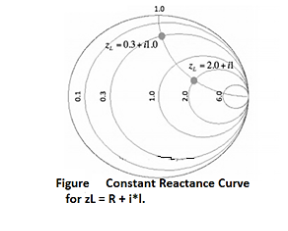
The resulting curve zL = R + i is plotted in green in Figure above. A few points along the curve are illustrated as well. Observe that zL = 0.3 + i is at the intersection of the Re[zL] = 0.3 circle and the Im[zL]=1 curve. Similarly, observe that the zL = 2 + i point is at the intersection of the Re[zL]=2 circle and the Im[zL]=1 curve. (For a quick reminder of real and imaginary parts of complex numbers, see complex math primer.) The constant reactance curve, defined by Im[zL]=-1 is shown in Figure below:
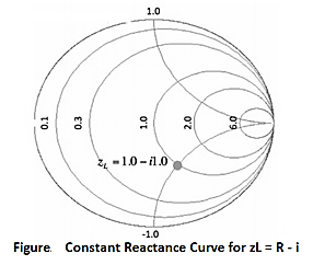
The resulting curve for Im[zL]=-1 is plotted in green in Figure above. The point zL=1-i is placed on the Smith Chart, which is at the intersection of the Re[zL]=1 circle and the Im[zL]=-1 curve.
An important curve is given by Im[zL]=0. That is, the set of all impedances given by zL = R, where the imaginary part is zero and the real part (the resistance) is greater than or equal to zero. The result is shown in Figure below:
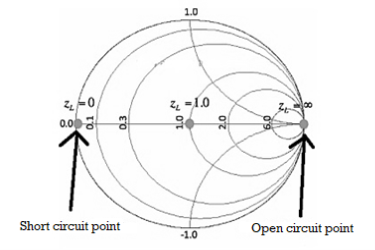
Figure. Constant Reactance Curve for zL=R. The reactance curve given by Im[zL]=0 is a straight line across the Smith Chart.
There are 3 special points along this curve.
On the far left, where zL = 0 + i0, this is the point where the load is a short circuit, and thus the magnitude of is 1, so all power is reflected. In the center of the Smith Chart, we have the point given by zL = 1. At this location, is 0, so the load is exactly matched to the transmission line. No power is reflected at this point.
The point on the far right in Figure aboce is given by zL = infinity. This is the open circuit location. Again, the magnitude of is 1, so all power is reflected at this point, as expected. Finally, we'll add a bunch of constant reactance curves on the Smith Chart, as shown in Figure below.
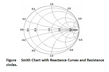
In Figure, we added constant reactance curves for Im[zL]=2, Im[zL]=5, Im[zL]=0.2, Im[zL]=0.5, Im[zL]=-2, Im[zL]=-5, Im[zL]=-0.2, and Im[zL] = -0.5. Figure above shows the fundamental curves of the Smith Chart.
PROBLEMS:
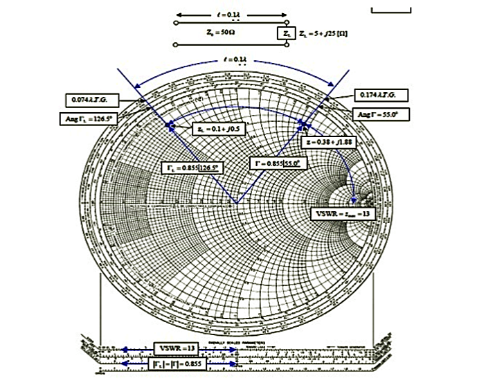
(i). The 0.1λ length line shown has a characteristic impedance of 50 and is terminated with a load impedance of ZL = 5+j25.
(a) Locate zL = ZL/Z0 = 0.1 + j0.5 on the Smith chart.
(b)What is the impedance at l = 0:1λ?
Since we want to move away from the load (i.e., toward the generator), read 0.074 λ on the wavelengths toward generator scale and add l = 0.1 λ to obtain 0.174 λ on the wavelengths toward generator scale.
A radial line from the center of the chart intersects the constant reflection Co-efficient magnitude circle at z = 0.38 + j1.88. Hence Z = zZ0 = 50(0.38 + j1.88) = 19 + 94Ω.
(c) What is the VSWR on the line?
Find VSWR = Zmax = 13 on the horizontal line to the right of the chart's center. Or use the SWR scale on the chart.
(d) What is ΓL?
From the reflection coefficient scale below the chart,
Find |ΓL| = 0.855. From the angle of reflection coefficient scale on the perimeter of the chart, Find the angle of ΓL=126.5₀. HenceΓL=0.855e j126.5₀.
(e) What is Γ at l = 0.1λ from the load?
Note that |Γ| =|ΓL|=0.855. Read the angle of the reflection coefficient from the angle of reflection coefficient scale as 55.0₀. Hence ΓL=0.855e j126.5₀.
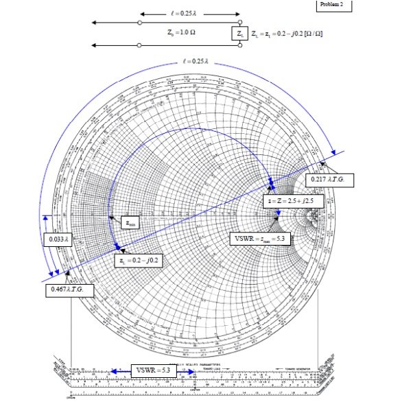
(ii). A transmission line has Z0 = 1.0, ZL = zL = 0.2- j0.2Ω.
(a) What is z at l =λ/4=0.25 λ?
From the chart, read 0:467λfrom the wavelengths to-ward generator scale. Add 0.25λ to obtain 0.717 λ on the wavelengths toward generator scale. This is not on the chart, but since it repeats every half wavelength, it is the same as 0.717 λ– 0.500 λ = 0.217 λ. Drawing a radial line from the center of the chart, we find an intersection with the constant reflection coefficient magnitude circle at z = Z = 2.5 + j2.5.
(b) What is the VSWR on the line?
From the intersection of the constant reflection coefficient circle with the right hand side of the horizontal axis, read VSWR= zmax = 5.3.
(c) How far from the load is the first voltage minimum?
The voltage minimum occurs at zmin which is at a distance of 0.500λ-0.467λ = 0:033λ from the load. Or read this distance directly on the wavelengths toward load scale. The current minimum occurs at zmax which is a quarter of a wavelength farther down the line or at 0.033λ+0.25λ = 0.283λ from the load.
(iii) A slotted line measurement yields the following parameter values:
(a) Voltage minima at 9.2 cm and 12.4 cm measured away from the load with the line terminated in a short.
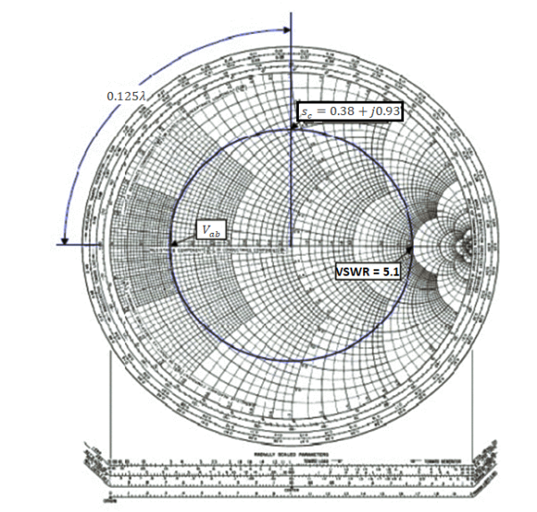
(b) VSWR = 5.1 with the line terminated in the unknown load; a voltage minimum is located 11.6 cm measured away from the load.
What is the normalized line impedance?
Note that this data could have come from either a waveguide or a TEM line measurement. If the transmission system is a waveguide, then the wavelength used is actually the guide wavelength. From the voltage minima on the shorted line, the (guide) wavelength may be determined:
λg/2=12.4cm-9.2 cm=3.2 cm or λg=6.4 λg
Hence the shift in the voltage minimum when the load is replaced by a short is
12.4cm-11.6cm/6.4cm/ λg=0.125 λg
Toward the generator. Locate the reflection coefficient magnitude circle by its intersection with zmax = VSWR = 5:1 on the horizontal axis. Then from the voltage minimum opposite zmax, move 0.125 λg toward the generator to find a position an integral number of half-wavelengths from the load. The impedance there is the same as that of the load, zL = 0.38 +j0.93. Alternatively, move 0.5 λg– 0.125 λg = 0.375 λg toward the load to locate the same value.
General solution, physical significance of the equations, wavelength, velocity of propagation, the distortion less line, Reflection on a line not terminated in Z0, reflection coefficient, open and short circuited lines, reflection factor and reflection loss, standing waves; nodes; standing wave ratio, Input impedance of dissipation less line, Input impedance of open- and short-circuited lines, Power and impedance measurement on lines, Reflection losses on the unmatched Load, Problems solving using Smith chart.
- Short-Circuit Lines:
Consider a transmission line of length L, but suppose the end of line is short-circuited together so that ZA =0. Then the impedance equation is:

We can determine input impedance for short circuit line:(input admittance 1/Z)
 (short-circuited Line)
 (short-circuited admittance)
Example:
Suppose an antenna has an impedance ZA = 50 – j * 10. Using short-circuit transmission line with Z0 = 50 and u=c in parallel with antenna. Transform the input impedance to be entire real.
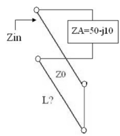
The admittance of the load is:
YA = 1/ZA = 1/ (50 – j * 10) = YA = 0.0192 + j * 0.0038
If reactance is added in parallel with a value of YA = - j * 0.0038 the admittance will be entirely real so the impedance will real.
References:
1. WH Hayt and JA Buck, “Engineering Electromagnetic”, McGraw- Hill Education.
2. Antenna and wave propagation by k.d parsad satya prakashan.