Unit - 2
Wave optics
Division of Wave front: In this class, the coherent sources are gotten by separating the input wave front, originating from a common source, by means of mirrors, bi prisms or lenses.
This group of interference involves fundamentally a point source or a narrow-slit source. The instruments used to get interference by division of wave front are, Young’s double slit Experiment, the Fresnel biprism, Fresnel mirrors, Lloyd's mirror, lasers, etc.

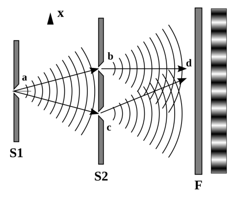
Fig:1 Young’s double slit Experiment
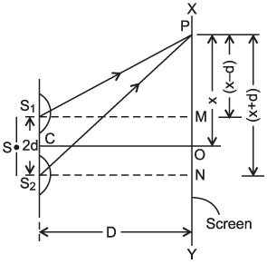
Fig.2: Ray diagram
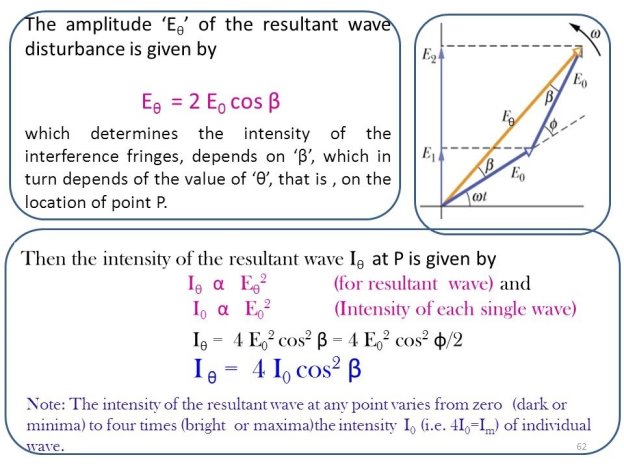
Separation of Amplitude: In this procedure, the amplitude of the input beam is separated into two or more parts both by partial reflection or refraction. Therefore, we have coherent beams made by division of amplitude.
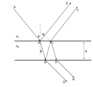
Fig.3: Ray diagram
These beams travel dissimilar paths and are lastly brought collected to produce interference. The effects resulting from the superposition of two beams are mentioned to as two beam interference and those resultant from superposition of more than two beams are mentioned to as multiple beam interference.
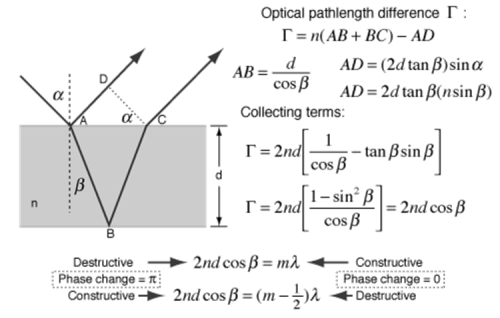
The interference in thin films: Newton's rings and Michelson's interferometer are cases of two beam interference and Fabry-Perot's interferometer is a instance of several beam interference.
Interference in light waves occurs whenever two or more waves overlap at a given point.
TYPES OF INTERFERENCE
The interference of light waves can be either constructive interference or destructive interference.
- Constructive Interference: Constructive interference takes place when the crest of one wave falls on the crest of another wave such that the amplitude is maximum. These waves will have the same displacement and are in the same phase.
- Destructive Interference: In destructive interference, the crest of one wave falls on the trough of another wave such that the amplitude is minimum. The displacement and phase of these waves are not the same.
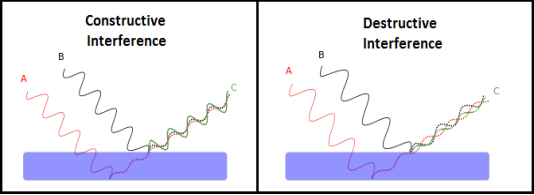
Figure 4: Constructive interference & destructive interference
We know that the superposition of two mechanical waves can be constructive or destructive. In constructive interference, the amplitude of the resultant wave at a given position or time is greater than that of either individual wave, whereas, in destructive interference, the resultant amplitude is less than that of either individual wave.
Light waves also interfere with each other. Fundamentally, all interference associated with light waves arises when the electromagnetic fields that constitute the individual waves combine.
If two light bulbs are placed side by side, no interference effects are observed because the light waves from one bulb are emitted independently of those from the other bulb. The emissions from the two light bulbs do not maintain a constant phase relationship with each other over time. Light waves from an ordinary source such as a light bulb undergo random phase changes in time intervals less than a nanosecond.
Therefore, the conditions for constructive interference, destructive interference, or some intermediate states are maintained only for such short time intervals. Because the eye cannot follow such rapid changes, no interference effects are observed. Such light sources are said to be incoherent.
COHERENT SOURCES
Two sources are said to be coherent when the waves emitted from them have the same frequency and constant phase difference.
Interference from such waves happen all the time, the randomly phased light waves constantly produce bright and dark fringes at every point. But, we cannot see them since they occur randomly. A point that has a dark fringe at one moment may have a bright fringe at the next moment. This cancels out the effect of the interference effect, and we see only an average brightness value. The interference is not said to be sustained since we cannot observe it.
Definition: - A predictable correlation of the amplitude and phase at any one point with another point is called coherence.
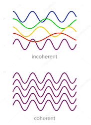
Figure 5: Incoherence & coherence
Two waves are said to be coherent, the waves must have
In the case of conventional light, the property of coherence exhibits between a source and its virtual source whereas in the case of laser the property coherence exists between any two or more light waves.
There are two types of coherence
i) Temporal coherence
Ii) Spatial coherence
TEMPORAL COHERENCE (OR LONGITUDINAL COHERENCE):
The predictable correlation of amplitude and phase at one point on the wave train w.r.t another point on the same wave train, then the wave is said to be temporal coherence
To understand this, let us consider two points P1 and P2 on the same wave train, which is continuous as shown in the figure.

Figure 6: Wave train
Suppose the phase and amplitude at any one point is known, then we can easily calculate the amplitude and phase for any other point on the same wave train by using the wave equation
y= a sin (2π(ct-x)/ λ)
Where ‘a’ is the amplitude of the wave and ‘x’ is the displacement of the wave at any instant of time ‘t’.
SPATIAL COHERENCE (OR TRANSVERSE COHERENCE)
The predictable correlation of amplitude and phase at one point on the wave train w. r .t another point on a second wave, then the waves are said to be spatial coherence (or transverse coherence)
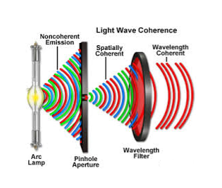
Figure 7: Spatial Coherence
CONDITIONS OF INTERFERENCE
In a sustained interference pattern, the position of maximum and minimum intensity regions remains constant with time. To obtain sustained interference, the following conditions are required:
- The sources must be coherent, that is, they must maintain a constant phase with respect to each other.
- The two light sources must emit continuous waves of the same wavelength and have the same period.
- The distance between the two sources of light must be small. This gives large fringe width so that the fringes are separately visible.
- The sources should be monochromatic, that is, of a single wavelength.
- The two light sources must emit waves in nearly the same direction.
- The light source must be a point source.
- The distance between the two sources and the screen must be large. This gives again large fringe width so that the fringes are separately visible.
Key Takeaways
- Interference in light waves occurs whenever two or more waves overlap at a given point.
- The interference of light waves can be either constructive interference or destructive interference.
- To obtain sustained interference; the sources must be coherent.
- There are two types of coherence: Temporal coherence & Spatial coherence
A film of thickness from 0.5 to 10 μm is a transparent medium of glass, mica, air enclosed between glass, soap film, etc. When the light is made incident on this thin film partial reflection and partial refraction occur from the top surface of the film. The refracted beam travels in the medium and again suffers partial reflection and partial refraction at the bottom surface of the film. In this way several reflected and refracted rays are produces by a single incident ray. As they moves are superimposed on each other and produces interference pattern.
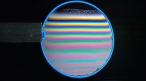
Figure 8
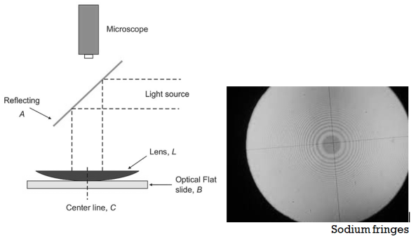
Fig.9: Newton’s Ring
The principle is often used in testing the uniformity of a polished surface by studying the interference pattern the surface makes when placed in contact with a perfectly flat glass surface.
The figure shows contour patterns formed by various surfaces under test.
In the figure, A is produced by a flat surface with point of contact at X. In B and C the test surface is slightly convex, the points of contact indicated by X in each case. An irregular surface may give an interference pattern shown in D, with two points of contact X1 and X2.

Fig. 10: 3D surface
Diffraction
When the light falls on the obstacle whose size is comparable with the wavelength of light then the light bends around the obstacle and enters the geometrical shadow. This bending of light is called diffraction.
Diffraction is a slight bending of light as it passes around the edge of an object. The amount of bending depends on the relative size of the wavelength of light to the size of the opening. If the opening is much larger than the light's wavelength, the bending will be almost unnoticeable. However, if the two are closer in size or equal, the amount of bending is considerable, and easily seen with the naked eye.
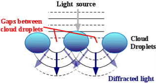
Figure 11: Diffraction of light
In the atmosphere, diffracted light is bent around atmospheric particles -- most commonly, the atmospheric particles are tiny water droplets found in clouds. Diffracted light can produce fringes of light, dark or colored bands. An optical effect that results from the diffraction of light is the silver lining sometimes found around the edges of clouds or coronas surrounding the sun or moon. The illustration above shows how light (from either the sun or the moon) is bent around small droplets in the cloud.
Optical effects resulting from diffraction are produced through the interference of light waves. To visualize this, imagine light waves like water waves. If water waves were incident upon a float residing on the water surface, the float would bounce up and down in response to the incident waves, producing waves of their own. As these waves spread outward in all directions from the float, they interact with other water waves. If the crests of two waves combine, an amplified wave is produced (constructive interference). However, if a crest of one wave and a trough of another wave combine, they cancel each other out to produce no vertical displacement (destructive interference).
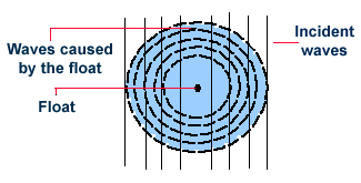
Figure 12: Diffraction
This concept also applies to light waves. When sunlight (or moonlight) encounters a cloud droplet, light waves are altered and similarly interact with one another as the water waves described above. If there is constructive interference, (the crests of two light waves combining), the light will appear brighter. If there is destructive interference, (the trough of one light wave meeting the crest of another), the light will either appear darker or disappear entirely.
Types of Diffraction
There are two types of diffractions
- Fresnel Diffraction: Fresnel diffraction is produced when light from a point source meets an obstacle, the waves are spherical and the pattern observed is a fringed image of the object.
- Fraunhofer Diffraction: Fraunhofer diffraction occurs with plane wave-fronts with the object effectively at infinity. The pattern is in a particular direction and is a fringed image of the source.
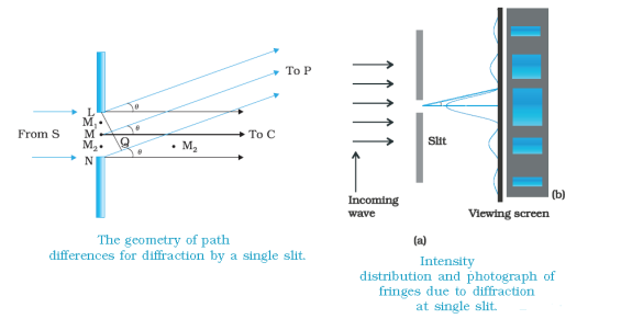
Figure 13: Types of diffractions Fresnel Diffraction & Fraunhofer Diffraction
From the above figure, we observe that the source is located at a finite distance from the slit, and the screen is also at a finite distance from the slit. The source and the screen are not very far from each other. So this is Fresnel diffraction. Here, if suppose the ray of light comes exactly at the edge of the obstacles, the path of the light is changed. So the light bends a little and meets the screen.
A beam of width α travels a distance of α2/λ, called the Fresnel distance before it starts to spread out due to diffraction. But when the source and the screen are far away from each other, and when the source is located at the infinite position, then the ray of light coming from that infinite source are parallel rays of light. So this is Fraunhofer diffraction.
Here we have to make use of the lens. But why do we use the lens? Because in Fraunhofer diffraction, the source is at infinity so the rays of light that pass through the slit are parallel rays of light.
So to make these rays parallel to focus on the screen, we, make use of the converging lens. The zone which we get in front of the slit in the central maxima. On either side of the central maxima, there is a bright zone i.e. 1st maxima.
Comparison
Fresnel Diffraction | Fraunhofer diffraction |
1 If the source of light and screen is at a finite distance from the obstacle, then the diffraction is called Fresnel diffraction. | 1 If the source of light and screen is at an infinite distance from the obstacle then the diffraction is called Fraunhofer diffraction. |
2 The corresponding rays are not parallel. | 2 The corresponding rays are not parallel. |
3 The wavefronts falling on the obstacle are not plane. | 3 The wavefronts falling on the obstacle are planes. |
4 No convex lens is needed to converge spherical wavefronts. | 4 Plane diffracting wavefronts are converged by means of a convex lens to produce a diffraction pattern. |
5 Fresnel diffraction patterns on flat surfaces. | 5 Fraunhofer diffraction patterns on spherical surfaces. |
6 Diffraction patterns Change as we propagate them further ‘downstream’ of the source of scattering. | 6 Diffraction patterns Shape and intensity of a Fraunhofer diffraction pattern stay constant. |
7 To obtain Fresnel diffraction, zone plates are used. | 7 To obtain Fraunhofer diffraction, the single-double plane diffraction grafting is used. |
8 Diffraction pattern moves along the corresponding shift in the object. | 8 Diffraction pattern remains in a fixed position. |
DIFFRACTION: HUYGEN’S PRINCIPLE
Huygens' Principle
In 1678 Huygens proposed a model where each point on a wavefront may be regarded as a source of waves expanding from that point.
Every point on a wavefront is a source of wavelets that spread out in the forward direction at the same speed as the wave itself. The new wavefront is a line tangent to all of the wavelets.
So Huygens’s Principle states that every point on a wavefront is a source of wavelets, which spread forward at the same speed.
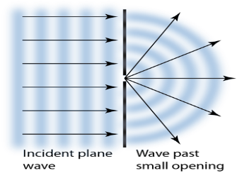
Figure 14: Huygens' Principle
The expanding waves may be demonstrated in a ripple tank by sending plane waves toward a barrier with a small opening. If waves approaching a beach strike a barrier with a small opening, the waves may be seen to expand from the opening.
Huygens-Fresnel Theory:
According to Huygens’s wave theory of light, each progressive wave produces secondary waves, the envelope of which forms the secondary wavefront.
In figure 20 (a). S is a source of monochromatic light and MN is a small aperture. XY is the screen placed in the path of light. AB is the illuminated portion of the screen and above A and below B is the region of the geometrical shadow. Considering MN as the primary wavefront. According to Huygens’s construction, if secondary wavefronts are drawn, one would expect encroachment of light in the geometrical shadow. Thus, the shadows formed by small obstacles are not sharp. This bending of light round the edges of an obstacle or the encroachment of light within the geometrical shadow is known as diffraction. Similarly, if an opaque obstacle MN is placed in the path of light [Figure 20 (b)], there should be illumination in the geometrical shadow region AB also. But the illumination in the geometrical shadow of an obstacle is not commonly observed because the light sources do not point sources and secondly the obstacles used are very large compared to the wavelength of light. If a shadow of an obstacle is cast by an extended source, say a frosted electric bulb, light from every point on the surface of the bulb forms its diffraction pattern (bright and dark diffraction bands) and this overlap such that no single pattern can be identified. The term diffraction is referred to such problems in which one considers the resultant effect produced by a limited portion of a wavefront.
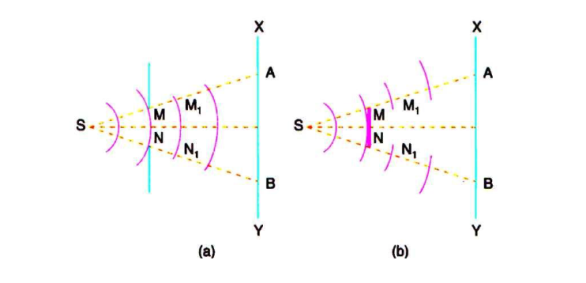
Figure 15: Huygens' Principle
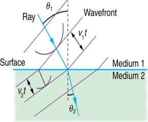
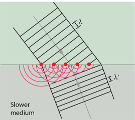
Huygens' principle provides a convenient way to visualize refraction. If points on the wavefront at the boundary of a different medium serve as sources for the propagating light, one can see why the direction of the light propagation changes.
The law of refraction can be explained by applying Huygens’s principle to a wavefront passing from one medium to another (see Figure 21). Each wavelet in the figure was emitted when the wavefront crossed the interface between the media. Since the speed of light is smaller in the second medium, the waves do not travel as far in a given time, and the new wavefront changes direction as shown. This explains why a ray changes direction to become closer to the perpendicular when light slows down.
 |  |
(a) | (b) |
Figure 16: Law of refraction by applying Huygens’s principle
If we pass light through smaller openings, often called slits, we can use Huygens’s principle to see that light bends as sound does. The bending of a wave around the edges of an opening or an obstacle is called diffraction.
Diffraction is a wave characteristic and occurs for all types of waves. If diffraction is observed for some phenomenon, it is evidence that the phenomenon is a wave. Thus the horizontal diffraction of the laser beam after it passes through slits is evidence that light is a wave.
Diffraction phenomena are part of our common experience. The luminous border that surrounds the profile of a mountain just before the sun rises behind it, the light streaks that one sees while looking at a strong source of light with half-shut eyes and the colored spectra (arranged in the form of a cross) that one sees while viewing a distant source of light through a fine piece of cloth are all examples of diffraction effects. Augustine Jean Fresnel in 1815, combined in a striking manner Huygens’ wavelet with the principle of interference and could satisfactorily explain the bending of light round obstacles and also the rectilinear propagation of light.
Key Takeaways
- When the light falls on the obstacle whose size is comparable with the wavelength of light then the light bends around the obstacle and enters the geometrical shadow. This bending of light is called diffraction.
- There are two types of diffractions Fresnel Diffraction & Fraunhofer Diffraction
- Fresnel diffraction is produced when light from a point source meets an obstacle, the waves are spherical and the pattern observed is a fringed image of the object.
- Fraunhofer diffraction occurs with plane wave-fronts with the object effectively at infinity. The pattern is in a particular direction and is a fringed image of the source.
- Huygens' Principle states that every point on a wavefront is a source of wavelets that spread out in the forward direction at the same speed as the wave itself. The new wavefront is a line tangent to all of the wavelets.
When light passes through a single slit having width w is of the order of the wavelength of the light, it can be observed that a single slit diffraction pattern on a screen that is a distance L >> w away from the slit.
The intensity is a function of angle. Huygens' principle says that each part of the slit can be thought of as an emitter of waves. All these waves interfere to produce the diffraction pattern.
When crest meets crest, we have constructive interference and when crest meets trough, we have destructive interference.
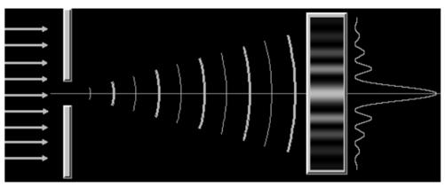
Figure 17. Single slit
- The wave-fronts at larger distance from the point source are essentially plane waves. This is called the Fraunhofer regime and the diffraction pattern is called Fraunhofer diffraction.
- The positions of all maxima (constructive interference) and minima (destructive interference) in the Fraunhofer diffraction pattern can be calculated easily.
- The Fraunhofer approximation, however, is only valid when the source, aperture, and detector are all very far apart or when lenses are used to convert spherical waves into plane waves.
Conditions for maxima and minima
Fig(a)
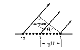
Fig (b)
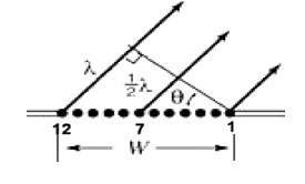
Fig 18 Slit diagram
- Consider a slit of width w, as shown in the diagram. A plane wave is incident from the bottom and all points oscillate in phase inside the slit.
- For light leaving the slit in a particular direction defined by the angle θ, there is a possibility that destructive interference happens between the ray at the right edge (ray 1) and the middle ray (ray 7).
- To arrive at a distant screen perpendicular to the direction of propagation of the rays, the rays coming from different points inside the slit have to travel different distances.
- They have a different optical path length. If ray 7 has to travel an extra distance of one-half wavelength (λ/2) compared to ray 1, then ray 1 and ray 7 destructively interfere. Crest meets trough.
- The optical path length of a light ray traveling from point A to point B is defined as c times the time it takes for the ray to travel from A to B.
- In free space the optical path length is just the distance d between the points. In a transparent medium with index of refraction n, it equals n times this distance, OPL = nd, because the light moves with speed c/n.
If the optical path length of two rays differs by λ/2, then the two rays interfere destructively.
For ray 1 and ray 7 to be half a wavelength out of phase we need
(w/2)sinθ = λ/2 or
w sinθ = λ.
Destructive interference produces dark fringes. Dark fringes in the diffraction pattern of a single slit are found at angles θ for which
w sin θ = mλ,
Where m is an integer, m = 1, 2, 3, ... . For the first dark fringe we have w sin θ = λ.
When w is smaller than λ, the equation w sin θ = λ has no solution and therefore no dark fringes are produced.
If the interference pattern is viewed on a screen at a distance L from the slits, then the wavelength can be found from the spacing of the fringes.
We have λ = w sin θ/m and sin θ = z/(L2 + z2)½), or
λ = zw/(m(L2 + z2)½
Where z is the distance from the centre of the interference pattern to the mth dark line in the pattern.
If L >> z then (L2 + z2)½ ~ z/L and we can write
λ = zw/(mL).
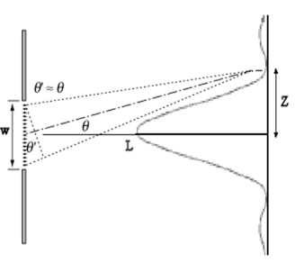
Fig 19. Slit for L>> z
Diffraction pattern
λ = a sin θ≈aθ
⇒θ = yD = λa
⇒ y = λDa
The width of the central maximum is simply twice this value
⇒ Width of central maximum = 2λDa
⇒ Angular width of central maximum = 2θ = 2λa
The diffraction pattern and intensity graph is shown below.
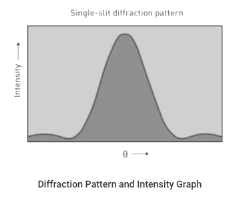
Fig 20. Single-silt diffraction pattern.
Double slits
The diffraction pattern of two slits of width aa that are separated by a distance d is the interference pattern of two-point sources separated by d multiplied by the diffraction pattern of a slit of width a. In other words, the locations of the interference fringes are given by the equation
Dsinθ=mλ
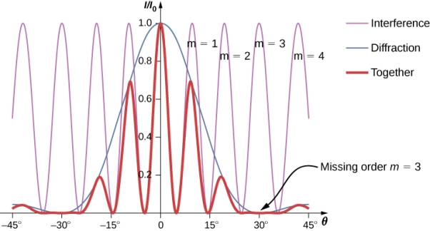
Fig.21: Diffraction from double slit
Numerical:
Determine the angle for the double-slit interference fringe, using the equation from Interference, then determine the relative intensity in that direction due to diffraction.
Solution
From interference, we know that the bright interference fringes
Occur at dsinθ=mλ, or
Sinθ=mλ/d
From Equation of double slit diffraction,
I=I0(sinβ/β)2
Where
β=ϕ/2=πasinθ/λ
Substituting from above,
β=πasinθ/λ=πamλ/λd=mπa/d.
For a=2λ,d=6λ and m=1,
β=(1)π(2λ)/(6λ)=π/3.
Then, the intensity is
I=I0(sinβ/β)2
=I0(sin(π/3)/( π/3))2=0.684I0.
A light wave is an electromagnetic wave that travels through the vacuum of outer space. Light waves are produced by vibrating electric charges. For our purposes, it is sufficient to merely say that an electromagnetic wave is a transverse wave that has both an electric and a magnetic component.
Let's suppose that we use the customary slinky to model the behaviour of an electromagnetic wave. As an electromagnetic wave travelled towards you, then you would observe the vibrations of the slinky occurring in more than one plane of vibration. This is quite different than what you might notice if you were to look along a slinky and observe a slinky wave traveling towards you. Indeed, the coils of the slinky would be vibrating back and forth as the slinky approached; yet these vibrations would occur in a single plane of space. That is, the coils of the slinky might vibrate up and down or left and right. Yet regardless of their direction of vibration, they would be moving along the same linear direction as you sighted along the slinky. If a slinky wave were an electromagnetic wave, then the vibrations of the slinky would occur in multiple planes. Unlike a usual slinky wave, the electric and magnetic vibrations of an electromagnetic wave occur in numerous planes. A light wave that is vibrating in more than one plane is referred to as unpolarized light. Light emitted by the sun, by a lamp in the classroom, or by a candle flame is unpolarized light. Such light waves are created by electric charges that vibrate in a variety of directions, thus creating an electromagnetic wave that vibrates in a variety of directions. This concept of unpolarized light is rather difficult to visualize. In general, it is helpful to picture unpolarized light as a wave that has an average of half its vibrations in a horizontal plane and half of its vibrations in a vertical plane.
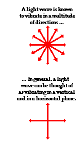
Fig.22: Polarization
The phenomena of interference and diffraction confirm the wave nature of light hence neither of these phenomena can identify the nature of waves that light is. These phenomena do not tell whether the oscillation of light waves is longitudinal or transverse. This is accomplished by the study of polarization.
A light wave that is vibrating in more than one plane is referred to as unpolarized light.
Example: Light emitted by the sun, by a lamp in the classroom, or by a candle flame is unpolarized light.
This unpolarized light is created by electric charges that vibrate in a variety of directions, this concept of unpolarized light is difficult to visualize. For simplicity, it is helpful to visualize unpolarized light as a wave that has an average of half its vibrations in a horizontal plane and half of its vibrations in a vertical plane. It is possible to transform unpolarized light into polarized light.
Polarized light waves are light waves in which the vibrations occur in a single plane. The process of transforming unpolarized light into polarized light is known as polarization.
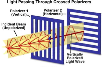
Figure 23: Polarization
Classification of light
Light in the form of a plane wave in space is said to be linearly polarized. Light is a transverse electromagnetic wave, but natural light is generally unpolarized, all planes of propagation being equally probable. If the light is composed of two plane waves of equal amplitude by differing in phase by 90°, then the light is said to be circularly polarized. If two plane waves of differing amplitude are related in phase by 90°, or if the relative phase is other than 90° then the light is said to be elliptically polarized.
Linearly Polarized: Light in the form of a plane wave in space is said to be linearly polarized. The electric field of light is limited to a single plane along the direction of propagation.
Circularly Polarized If the light is composed of two plane waves of equal amplitude by differing in phase by 90°, then the light is said to be circularly polarized. If the thumb of your right hand were pointing in the direction of propagation of the light, the electric vector would be rotating in the direction of your fingers.
Elliptically Polarized If two plane waves of differing amplitude are related in phase by 90°, or if the relative phase is other than 90° then the light is said to be elliptically polarized. If the thumb of your right hand were pointing in the direction of propagation of the light, the electric vector would be rotating in the direction of your fingers.
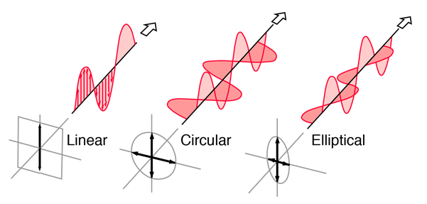
Figure 24: Showing Linear, Circular and Elliptical Polarization
POLARIZATION BY REFLECTION
Production of Polarized Light by Reflection
Brewster’s law can be used to polarise the light by reflection. When unpolarized light is incident on the boundary between two transparent media, the reflected light is polarised with its electric vector perpendicular to the plane of incidence when the refracted and reflected rays make a right angle with each other.
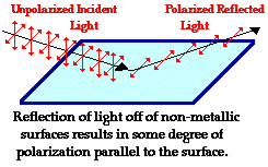
Figure 25: Polarization by Reflection
Thus we have seen that when the reflected wave is perpendicular to the refracted wave, the reflected wave is polarised. The electric field vectors of all unpolarized light may be resolved into two components as follows;
- Tangential component- in the plane of incidence.
- Normal components – in the plane perpendicular to the plane of incidence.
The angle of incidence, in this case, is called Brewster’s angle


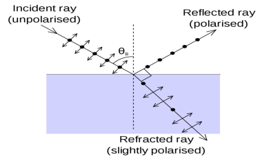

Figure 26: Polarization by Reflection
If the angle of incidence θi is varied, the reflected coefficient ‘r’ for the em waves corresponding to the tangential component will vary as shown in the figure. As θi increases r will decrease.
At θi = Brewster angle (about 57° for glass) r will be zero and no reflection of the tangential component will take place.
The reflected beam will contain light waves having only the normal component for the electric field as shown in the figure that is the reflected light will be plane-polarized with the oscillations of electric field vector normal to the plane of incidence.
Cause of Polarization by Reflection
The EM waves are generated because of the oscillation of electric charge. The electric field vectors of the transmitted ray act on the electrons in the dielectric.
Since the intensity of EM wave emitted by the oscillating charge is maximum in a direction normal to the plane of oscillation, and zero along the line of oscillations for the plane-polarized light having electric field vector in the plane of incidence, there will be no emission of EM waves in a direction normal to the reflected ray. In the figure, the direction along which no emission should occur is called a zero-intensity line. Let the angle between the reflected ray and the zero-intensity line be 𝛿 the angle between the reflected and transmitted ray is π/2 + 𝛿 suppose we arrange the angle of incidence such that
n=sinθi / sinθr
n=sinθi / sin(π/2 – θi)
n=sinθi / cosθi
n=tan θi
That is possible when
θi + θr = π/2 according to Brewster’s law
From figure
θi + θr+ π/2 + = π
As θi + θr = π/2
So π/2+ π/2 + = π
= 0
The line of zero intensity and the reflected ray will coincide. Thus there will be no reflection of light when the angle of incidence is equal to Brewster’s angle.
Thus the unpolarized light can be polarized by reflection as the reflected beam will contain light waves having electric field vector oscillating along normal to the plane of the incidence only.
Key Takeaways
- Polarized light waves are light waves in which the vibrations occur in a single plane. The process of transforming unpolarized light into polarized light is known as polarization.
- Light in the form of a plane wave in space is said to be linearly polarized.
- Light is a transverse electromagnetic wave, but natural light is generally unpolarized, all planes of propagation being equally probable.
- If the light is composed of two plane waves of equal amplitude by differing in phase by 90°, then the light is said to be circularly polarized.
- If two plane waves of differing amplitude are related in phase by 90°, or if the relative phase is other than 90° then the light is said to be elliptically polarized.
- Brewster’s law can be used to polarise the light by reflection.
Brewster’s law is a relationship of light waves at the maximum polarization angle of light. This law is named after Sir David Brewster, a Scottish physicist, who proposed the law in the year 1811. The law states that the p-polarized rays vanish completely on different glasses at a particular angle.
Further, the polarization angle is also called Brewster’s angle. It is an angle of incidence where the ray of light having a p-polarization transmitted through a dielectric surface that is transparent without any reflection. While the unpolarized light at this angle is transmitted, the light is reflected from the surface.
Brewster was able to determine that the refractive index of the medium is numerically equal to the tangent angle of polarization.
μ=tan i
Where,
μ = Refractive index of the medium.
i= Polarization angle.
From Snell’s Law:
μ=sin i / sin r ……………. 1
From Brewster’s Law:
μ=tan i=(sin i/cosi ) …………… 2
Comparing both formulas: 1 and 2
Cosi=sinr=cos(π/2−r)
i=π/2–r, or i+r=π/2
As, i +r=π/2<ABC is also equal to the π/2. Therefore, the reflected and the refracted rays are at right angles to each other.
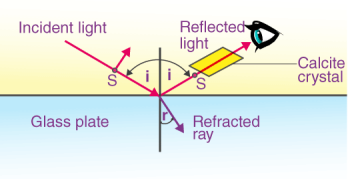
Fig.27: Brewster Angle
Relation Between Brewster Angle and Critical Angle
Brewster’s angle is given as:
Ө b = arc tan (n2/n1)
TanӨ b = n2/n1
The critical angle is given as:
Ө c = arc sin (n1/n2)
SinӨ c = n1/n2
SinӨ c = 1/(n2/n1)
But we know that,
TanӨ p = n2/n1
SinӨ c = 1/tanӨ b
Therefore,
Өc = arc sin (1/tanӨ b)
Application
One general example of the application of Brewster’s law is polarized sunglasses. These glasses use the principle of Brewster’s angle. The polarized glasses reduce glare that is reflecting directly from the sun and also from the horizontal surfaces like road and water. Photographers also use the same law to reduce the reflection from reflective surfaces by using a polarizing filter for the lens.
Numericals
Example 1:
What will be Brewster’s angle of light, if the light travels from water into the air. Assume that n = 1.33.
Solution:
Given,
n1 = 1.33
Brewster’s angle = tan-1 (n2/n1) = tan-1 (1.5/1.33) = 48.4o
Therefore, Brewster’s angle is 48.4o.
Example 2:
Determine the angle of refraction and polarization angle of the polarizer if the refractive index of the polarizer is 1.33.
Solution:
Given,
Refractive index of the polarizer = 1.33
According to Brewster’s law, μ = tan ip
Ip = tan-1 (1.33)
Ip = 53.06
Therefore,
Angle of refraction = ip + ir = 90o = 90o – 53.06 = 36.94
When light falls on a polarizer, the transmitted light gets polarized. The polarized light falling on another Polaroid, called analyzer, transmits light depending on the orientation of its axis with the polarizer.
The intensity of light transmitted through the analyzer is given by Malus’ law. The law describes how the intensity of light transmitted by the analyzer varies with the angle that its plane of transmission makes with that of the polarizer.
The law can be stated in words as follows:
The intensity of the transmitted light varies as the square of the cosine of the angle between the two planes of transmission.
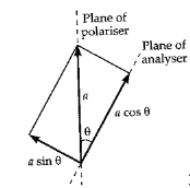
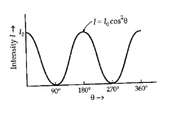
Figure 28. Polarizer
If Ao is the amplitude of the incident light and (At) is amplitude of the light transmitted through the analyzer; which in inclined at an angle θ with the polarizer then (fig 2 & 3),
At=Ao Cosθ..................................1
As Intensity ∝(amplitude)2
It = At2 = Ao2Cos2θ = IoCos2θ.................2
Where It is the intensity of the light transmitted through the analyzer; and Io is the intensity of the incident plane polarized light.
Consider the two extreme cases illustrated by this equation:
1 If θ is zero, the second polarizer (analyzer) is aligned with the first polarizer, and the value of cos2θ is one. Thus, the intensity transmitted by the second filter is equal to the light intensity that passes through the first filter. This case will allow maximum intensity to pass through.
2 If θ is 90˚, the second polarizer (analyzer ) is oriented perpendicular to the plane of polarization of the first filter, and the cos2(90˚) gives zero. Thus, no light is transmitted through the second filter. This case will allow minimum (zero) intensity to pass through.
The light intensity cannot be measured directly. The light energy is converted into electrical energy using photo detectors such as a photo cell or light dependent resistor (LDR).
In such photo detectors the current produced is directly proportional to the light intensity.
It ∝ current
It = K *current
The constant K appearing here is nothing but the conversion efficiency of photo detector.
Using this concept Malus’s law (equations 1 and 2) is verified in this experiment. The angles are noted experimentally from the dial fitted to the Polaroids.
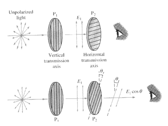
Figure 29 Mauls Law
- θd is the angle of diffraction measured from the normal.
- The diagram above shows the orders of the diffracted wavelength. As well as positive orders, light can also be diffracted in the opposite direction (i.e. n = -1, -2 etc.)
- Higher orders may also appear but these decrease in intensity. Usually the first order lines (n=1 or n=-1) are the most intense.
Double refraction, also called birefringence, an optical property in which a single ray of unpolarized light entering an anisotropic medium is split into two rays, each traveling in a different direction. One ray (called the extraordinary ray) is bent, or refracted, at an angle as it travels through the medium; the other ray (called the ordinary ray) passes through the medium unchanged.
Double refraction can be observed by comparing two materials, glass and calcite. If a pencil mark is drawn upon a sheet of paper and then covered with a piece of glass, only one image will be seen; but if the same paper is covered with a piece of calcite, and the crystal is oriented in a specific direction, then two marks will become visible.
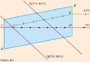
Fig.30 Double Refraction
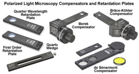
Fig.31: Retardation Plates
A retardation plate is an optically transparent material which resolves a beam of polarized light into two orthogonal components; retards the phase of one component relative to the other; then recombines the components into a single beam with new polarization characteristics.
The first order retardation plate is a standard accessory that is frequently utilized to determine the optical sign (positive or negative) of a birefringent specimen in polarized light microscopy. In addition, the retardation plate is also useful for enhancing contrast in weakly birefringent specimens.
There are three main types of waveplates: multiple order, low order, and zero order. The fundamental difference between these plates is the stability of the retardation tolerance across the wavelength range. This tolerance is a function of spectral range, product type, and design thickness.
References:
1. Fundamentals of Physics Electricity and Magnetism, Halliday and Resnick, tenth edition (published 2013).
2. Electricity, magnetism and light, W. Saslow, 1st edition
3. Electromagnetic Theory, Singh and Prasad, I. K. International Publication, 1/e
4. Electricity, Magnetism & Electromagnetic Theory, S. Mahajan and Choudhury, 2012, Tata McGraw
5. Elements of Electromagnetics, M.N.O. Sadiku, 2010, Oxford University Press.