Unit - 2
D.C Machines
Construction details of D.C. Machine
Whether machine is D.C. Generator or motor the construction basically remains the same.
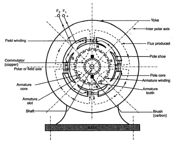
A cross section of typical D.C. Machine
1)Yoke
a) Functions
1. It serve the purpose of outermost cover of the D.C. Machine. So that the insulating materials get protected from harmful atmospheric elements like moisture. Dust and various gases like SO2, acidic fumes etc.
2. It provides mechanical support to the poles.
3. It forms a part of the magnetic circuit.
It provides a path of low reluctance for magnetic flux. The low reluctance path is important to avoid wastage of power to provide same flux large current and hence the power is necessary if the path has high reluctance to produce the same flux.
4.Choice of material: - It is prepared by using cast iron, silicon steel is used which provides high permeability i.e. low reluctance and gives good mechanical strength.
2) Poles
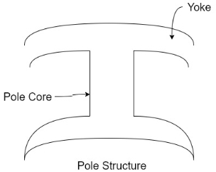
Pole structure
Each Pole is divided into two parts namely
- Pol core
- Pole shoe
Functions of pole core and pole shoe: -
- Pole core basically carries a field winding which is necessary to produce the flux.
- It directs the flux produced through air gap to armature core to the next pole.
- Pole shoe enlarge the area of armature core to come across the flux, which is necessary to produce larger induced e.m.f. To achieve this, sports shoe has been given a particular shape.
Choice of material: -
It is made up of magnetic material like cast iron or cast steel.
As it requires a definite shape and size, laminated construction is used. The laminations of required size and shape are stamped together to get a pole which is then bolted to the yoke.
3) Field Winding 
The field winding is wound on the pole core with a definite direction.
a) Functions:
To carry current due to which pole core on which the field winding is placed behaves as an electromagnet, producing necessary flux.
As it helps in producing the magnetic field i.e. exciting the poles as an electromagnet it is called Field winding or Exciting winding.
b) Choice of material:
It has to carry current hence obviously made up of some conducting material.
So aluminium or copper is the choice. But field coils are required to take four types of shape and bent about pole core and copper has good pliability i.e. it can be bend easily. So copper is the proper choice .field winding is divided into various coils called field coils. These are connected in series with each other and wound in such direction around pole cores, such that alternate 'N' and 'S' poles are formed.
The total number of poles is denoted as P.
4) Armature
The armature is further divided into two parts namely
- Armature core
- Armature winding
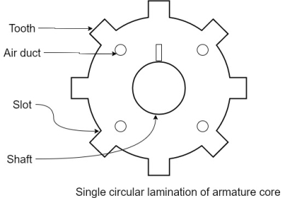
1.Armature core: Armature core is cylindrical in in shape mounted on the shaft. It consists of slots on its periphery and air ducts to permit the air flow through armature which serves cooling purpose.
a) Functions-
1) Armature core provides house for armature winding i.e. armature conductors.
2)To provide the path of low reluctance to the magnetic flux produced by the field winding.
b) Choice of material: -
As it has to provide a low reluctance path to the flux, it is made up of magnetic material like cast iron or cast steel.
It is made up of laminated construction to keep Eddy current loss as low as possible. A single circular lamination used for the construction of armature core is shown in figure.
3. Armature winding
Armature winding is nothing but the interconnection of the armature conductors placed in the slots provided on the armature core periphery.
When the armature is rotated in case of generator magnetic flux gets cut by armature conductors and e.m.f gets induced in them.
a) Functions
1) curvatures of e.m.f takes place in the armature winding in case of generators.
2) To carry the current supplied in case of D.C. Motors.
3) To do the useful work in the external circuit.
b) Choice of Material: -
As armature winding carries entire current which depends on external load, it has to be made up of conducting material which is copper.
5.Commutator
The basic nature of e.m.f in the armature conductors is alternating. This needs verification in case of D.C. Generator, which is possible by a device called commutator.
a) Functions:
1)To facilitate the collection of current from the armature conductors.
2) To convert internally developed alternating e.m.f to unidirectional (D.C.) e.m.f.
3) To produce unidirectional torque in case of motors
b) Choice of Material:
As it collects current from armature, it is also made up of copper segments.
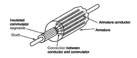
It is cylindrical in shape and is made up of wedge-shaped segments of hand drawn high conductivity copper .the segments are insulated from each other by thin layer of Mica.
Each commutator segment is connected to the armature conductor by means of copper lug or strip. This construction is shown in figure above.
6. Brushes and Brush Gear
Brushes are stationary and resting on the surface of the commutator.
a) Function-
To collect current from computer and make it available to stationary external circuit.
b) Choice of Material: -
Brushes are normally made up of soft material like carbon.
To avoid wear and tear of commentator the brushes are made up of soft material like carbon.
7) Bearings
Ball bearings are usually used as they are more reliable. For heavy duty machines roller bearing are preferred.
Armature Winding is the windings, in which voltage is induced. The Field Winding is the winding in which the main field flux is produced when the current through the winding is passed. Below are the types of armature windings.
Armature windings
Simple lap winding –
1) In this type of winding, the back and front pitches are odd and opposite in sign. They have difference of 2 or multiple of 9r.
2) The back and front pitches should be equal to pole pitch.
3) Average pitch, 
4) Commutator pitch, Yc = ±m.
5) Resultant pitch, YR = YB – YF.
6) The number of slots is half the number of coil sides.
7) YB = YF ± 2m (m=1, simplex wave winding)
If YB> YF, YB = YF + 2 (Right handed winding). Yc = +1
If YB< YF, YB = YF – 2 (Left handed winding). Yc = -1.
8) They are useful for low voltage, high current generators.
Simple Wave Winding
1) The back and front pitches both are odd and of same sign.
2) YB and YF are nearly equal to the pole pitches.
3) Resultant pitch, YR = YB + YF
4) Commutator pitch, YC= YA (for lap winding YC = ±1).

5) Average pitch, 
6) The number of coils, 
7) The number of armature parallel paths =2m
m = multiplicity of windings.
8) They are suitable for low current and high voltage generators.
9) It gives more emf than lap winding.
EMF Equation
In a DC motor when the armature rotates the conductors also rotate and hence cut the flux. According to the law of electromagnetic induction, the induced EMF is in the opposite direction (by Fleming’s Right hand rule) to the applied voltage. As it has opposite direction so it is referred to as back EMF (Eb).
Let φ = Flux /pole
P = Number of poles
Total flux produced by poles = φ x P
Time taken to complete one revolution= 60/N
N= speed of armature conductor in rpm
Let e be the induced emf of the armature conductor.
By Faraday’s Law e=
Induced emf in one conductor is given as
E=
E= φPN/60
Z = total numbers of conductor
A = number of parallel paths
Then,
Z/A = number of conductors connected in series
We know that induced emf in each path is same across the line
Therefore,
Induced emf of DC generator
E = emf of one conductor × number of conductor connected in series.
Induced emf of DC generator is
E= φP x
x volts
volts
For Simple wave wound generator numbers of parallel paths are only 2. So, A=2
Therefore,
E= φP x
x =
= volts
volts
Simple lap-wound generator
Here, number of parallel paths is equal to number of conductors in one path
i.e. P = A
Therefore,
Induced emf for lap-wound generator is
Eg= x
x volts
volts
The back emf induced is motor is same as the emf induced in generator
Eb= x
x volts
volts
Q1) A 220V, 4-pole, wave wound dc series motor has 680 conductors on its armature. It has armature and series field resistance of 0.75 ohm. The motor takes a current of 40 A. Calculate the speed and torque developed if flux/pole is 25mWb?
Sol: Eb= x
x
Eb=V-IaRa=220-40x0.75=190 volts
190=25x10-3x680x40x(4/2)xN
N=502.9 rpm
Q2) A 4-pole 220V shunt motor has 540 lap wound conductors. It takes 32A from the supply mains. The field windings take 1A. The armature resistance is 0.09 ohm and flux/pole is 30mWb. Calculate speed.
Sol: Eb=V-IaRa
Ia=32-1=31 A
Eb= 220-0.09x31=217.2V
Eb= x
x
217.2=
N=804.4 rpm
Motor Torque
Armature Torque (Ta) of motor –
Power developed = Ta × 2πN W
As electrical power is converted to mechanical =EbIb
So, power developed = Power converted
Ta × 2πN = EbIb


We can also conclude from the above eqn.

For series,


For shunt,
 is constant practically.

Shaft Torque (Tsh) –
The torque doing useful work is called as shaft torque, Tsh.
Motor output =Tsh × 2πN


Due to iron and friction losses in motor Ta – Tsh difference torque exists called as lost torque.
Key takeaway
For series,


For shunt,
 is constant practically.

For Shunt

Examples
Q. 1 A 4 pole dc generator runs at 650 rpm and generates emf of 220V. The armature is wave wound and has 790 conductors. If total flux/pole is 0.0145 Wb in each pole, find leakage coefficient.
Sol.
Leakage coefficient =
Working flux is given as


A = 2 for simple wave winding.

Leakage coefficient =
Q.2 A 4 pole lap wound dc shunt generator has a useful flux per pole of 0.05 Wb. The armature winding consists of 200 turns each of 0.06 u ohm resistance. Calculate the terminal voltage when running at 900 rpm with armature current of 50 A.
Sol
. Terminal voltage V =Ea – Ia Ra
Ia Ra = 50×Ra.

Z = 200×2=400 (each turn has two sides).
N = 900 rpm  = 0.05 Wb P = A = 4

Total resistance of 200 turns = 200 × 0.004 = 0.8 ohm
As there are 4 parallel paths, so resistance of each path = 0.8/4 = 0.2 ohm
There are 4 resistances in parallel of each of 0.2 ohm
Ra = 0.2/4 = 0.05 ohm
Ia Ra = 50×0.05 = 25 V
V = Ea – Ia Ra = 300 – 25 = 275 V
Q.3 A 220 V 4 pole wave wound dc series motor has 780 conductors on its armature. It has armature and series field resistance of 0.75 ohm. The motor takes a current of 30A. Find the speed and gross torque developed if flux/pole is 20 mWb?
Soln.
Back emf,

Eb = V – IaRa = 220 – (30×0.75) = 197.5 V
197.5 = 20 × 10-3 ×780×N×0.75
N = 16.88 ≈ 17


Ta = 158.97 Nm.
Q. 4 A 4 pole, 210 V shunt motor has 450 lap wound conductor. It takes 32 A from supply mains and develops output power of 4.5 kW. The field takes 1 A. The armature resistance is 0.09 ohm and flux per pole is 30 mWb. Calculate speed and torque.
Sol
Ia = 32-1 = 31 n
Eb = V – Ia Ra = 210 - (0.09×31) = 207.21 V


N = 920.9 rpm

Q. 5 A 220 V, dc shunt motor has an armature resistance of 0.3 ohm and field resistance of 105 ohm. At no load speed is 1200 rpm and armature current are 2.3 A on application of rated load speed drops to 1120 rpm. Find the current and power input when motor delivers rated load.
Sol.
N1 = 1200 rpm Eb1 = 220 – (0.3×2.3) = 219.31 V
N2 = 1120 rpm Eb2 = 220 – 0.3 Ia2


Ia2 = 37.93 A
Line current = Ia2 + Ish = 37.93 + (220/105) = 40 A
Power input = 220 × 40 = 8800 W
Q.6 A 230 V shunt motor runs at 1000 rpm at no load and takes 6A. The total armature resistance is 0.2 ohm and field resistance is 210 ohm. Calculate the speed when loaded and taking 40 A. Assume flux constant.
Soln.


Q. 7 The armature resistance of a 15 kW, 230 V series motor is 0? 1 ohm, the brush voltage drop is 3 V and series field resistance is 0.05 ohm. The motor takes 60 A speed is 600 rpm. Calculate speed when current is 100 A.
Soln.


Φ1 ∝ 60
Φ2 ∝ 100


N2=350.22 rpm
Q.8 A 230V DC Shunt motor takes 4A at no load when running at 600 rpm. The field resistance is 100 ohms. The resistance of armature at standstill gives a drop of 6V across armature terminals when 10A were passed through it. Find i) Speed at no load (ii) Torque. Normal input of motor is 6kW
Sol
i)Speed 
Ish=  =2.3A
=2.3A
F.L Power=6000
F.L line current=  =26.08A
Ia=26.08-2.3=23.78A
Ra= =0.6Ω
=0.6Ω


N=566.2 rpm
Ii)Torque 

Armature Reactions
When armature of a DC Machine carries current, the distributed armature winding produces its own mmf which is known as armature reaction. The figure is shown below.
The nature of armature reaction in a DC machine is cross magnetizing with its axis along the (90° to main pole).
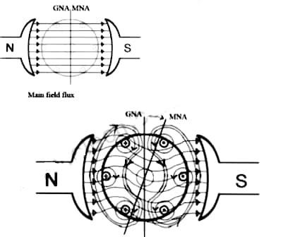
Fig MNA and GNA
MNA (Magnetic Neutral Axis) It is the axis along which no EMF generated in the armature conductors.
GNA (Geometrical Neutral Axis) It is perpendicular to the field axis.
When DC machine is running the flux due to armature and field winding exists. The armature flux is dominant on the later and hence disturbing the main field flux. This effect is called armature reaction in DC machines.
Example
Q. 1 A 4 pole, 210 V shunt motor has 450 lap wound conductor. It takes 32 A from supply mains and develops output power of 4.5 kW. The field takes 1 A. The armature resistance is 0.09 ohm and flux per pole is 30 mWb. Calculate speed and torque.
Soln. Ia = 32-1 = 31 n
Eb = V – Ia Ra = 210 - (0.09×31) = 207.21 V


N = 920.9 rpm


Q.2 A 220 V, dc shunt motor has an armature resistance of 0.3 ohm and field resistance of 105 ohm. At no load speed is 1200 rpm and armature current is 2.3 A on application of rated load speed drops to 1120 rpm. Find the current and power input when motor delivers rated load.
Soln. N1 = 1200 rpm Eb1 = 220 – (0.3×2.3) = 219.31 V
N2 = 1120 rpm Eb2 = 220 – 0.3 Ia2


Ia2 = 37.93 A
Line current = Ia2 + Ish = 37.93 + (220/105) = 40 A
Power input = 220 × 40 = 8800 W
Q.3 A 230 V shunt motor runs at 1000 rpm at no load and takes 6A. The total armature resistance is 0.2 ohm and field resistance is 210 ohms. Calculate the speed when loaded and taking 40 A. Assume flux constant.
Soln.


Q.4 The armature resistance of a 15 kW, 230 V series motor is 0? 1 ohm, the brush voltage drop is 3 V and series field resistance is 0.05 ohm. The motor takes 60 A speed is 600 rpm. Calculate speed when current is 100 A.
Soln.


Φ1 ∝60
Φ2 ∝100


N2=350.22 rpm
Q.5 A 230V DC Shunt motor takes 4A at no load when running at 600 rpm. The field resistance is 100 ohms. The resistance of armature at standstill gives a drop of 6V across armature terminals when 10A were passed through it. Find i) Speed at no load (ii) Torque. Normal input of motor is 6kW
Sol:
i)Speed 
Ish=  =2.3A
=2.3A
F.L Power=6000
F.L line current=  =26.08A
Ia=26.08-2.3=23.78A
Ra= =0.6Ω
=0.6Ω


N=566.2 rpm
Ii)Torque 

Basically, commutation means reversal of current in DC machines. In DC motors commutation is used to reverse the directions of DC current before being applied to the coils of the motor. The device used for commutation is called as commutator. The basic principle on which a motor works is electromagnetic induction. When current is passed through a conductor it produces magnetic field lines around it.
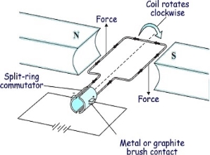
Fig: Motor effect
The conductor having magnetic field induced around it when placed in the path of magnetic lines of forces, they block the path. To remove this obstacle the lines of forces move either up or down according to the current direction. This gives rise to motor effect. Now if electromagnetic coil is placed between two magnets with opposite poles facing each other, the magnetic lines move the coil up when current is in one direction and down when current in opposite direction. This develops rotatory motion in coil. To change the direction of current in the coil, two half-moon shaped metals are attached to each end of the coil called Commutator. Metal brushes are placed with one end attached to the battery and the other end connected to the commutators.
Commutation in DC Machine
The armature coil has two commutators connected to its ends. When commutators and brushes are in contact current transformation can be attained. In DC machines we use more than one coil. As shown in below figure.
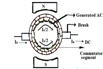
Fig: Commutation
Hence, we have more than one pair of commutator segments. The coil is short-circuited for a very short period of time with the help of brushes. This period is known as commutation period.
Reactance voltage: The coil in armature slot has self-inductance L. As we already know the direction of current is reversed in commutation. So, due to reversal of current and self-inductance a voltage is induced equal to . This voltage is also known as Reactance voltage.
Reactance voltage=
Tc= Commutation period.
I is maximum change in current in either direction.
So total change in current = I-(-I)=2I
Reactance voltage= 
1.11 is form factor of sinusoidal waveform.
Time of commutation:
By saying bad commutation, we only mean Sparking and burning while commutation. It can occur because of following reasons:
1.When Brushes position is not proper.
2. When spaces between brushes is not proper. This may be checked by marking an adding-machine tape around the commutator.
3. Mica should be between bars undercut about 0.063 in below the commutating surface.
4.When commutator is not ground, resulting in rough or burned commutator. Rough or burned commutator.
5. Grooved commutator. This may be prevented by properly staggering the brush sets so that the spaces between the brushes of an arm are covered by brushes of the same polarity of other arms.
6.When it has poor brush contact. It may be due to improper fitting of brush to commutator surface.
7.The brushes are not replaced correctly, i.e of same size or grade.
8.When the brushes do not move freely in their holder, irregularity occurs. This is called sticking brushes.
9.When operated for current density below 35A/in2,may lead to chattering of brushes. This can be corrected by lifting brushes to raise density
10. Due to poor line up or inadequate foundation Vibration occur.
11.The Short-circuited turns on the commutating or compensating fields can be the reason for bad commutation.
12. Because of open or very high resistance joints between the commutator neck and the coil leads can lead to the burning of bar at the bad joint.
13. A broken coil conductor produces an effect similar to that produced by the poor joints. In case of emergency the open coil may be opened at both ends, insulated from the circuit, and a jumper placed across the two affected necks.
14.With the resulting unbalanced air-gap fluxes under the poles, large circulating currents must be expected even with good armature cross connections.
15. Overloading.
Remedies:
There are basically three methods of improving commutation.
i)Resistance Commutation
Ii)Voltage Commutation
Iii)Compensation Windings
Below are explained briefly the methods of improving commutation
i)Resistance Commutation: The Resistance Commutation can be obtained by replacing low resistance copper brushes with high resistance carbon brushes. The use of Carbon brushes makes the contact resistance between commutator segments and brushes high. This high contact resistance has the tendency to force the current in the short-circuited coil to change according to the commutation requirements.
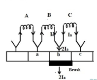
Fig: Resistance commutation
As seen from figure above Ia from the coil C cab reach brushes from two paths in commutation period. One path is direct through the commutator segment b and to the brush and the 2nd path is first through the short-circuit coil B and then through the commutator segment a and to the brush. The second path is shorter. When we use high resistance brushes then the contact area of brush with B decreases and contact area with A increases. But the resistance is inversely proportional to the contact area. So, Ra will decrease and Rb will increase according to the movement of brush.
Ii)Voltage Commutation: This method has two ways to improve commutation
a) Brush Shift
b) Commutating poles or interpoles.
In this method a voltage is induced in the coil undergoing commutation. This will help to neutralise the reactance voltage. The both voltages are opposing each other. So when injected and reactance voltages are equal, the direction of current in short circuited coil reverses, helping to attain sparkles commutation.
a) Brush Shift: The effect of armature reaction is to shift the magnetic neutral axis (MNA) in the direction of rotation for the generator and against the direction of rotation for the motor. Armature reaction establishes a flux in the neutral zone. A small voltage is induced in the commutating coil since it is cutting the flux.
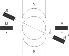
Fig: Brush Shift
b) Interpoles: The main function of interpoles is to induce an emf which is equal and opposite to that of reactance emf, which makes commutation sparkles. They also neutralize the cross magnetizing effect of armature reaction.
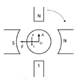
Fig: Interpoles
In above figure OF=MMF due to main poles.
OA=Cross Magnetizing MMF due to armature
BC= MMF due to interpoles.
BC is in opposition to OA. Hence it helps to cancel cross magnetization due to OA.
The ampere turns needed to cancel armature reaction ampere turn and to create the required flux is given as
ATi=ATa(peak)+
Bi=Flux density in interpole air gap
 =air gap of interpoles
Que) A 440V, 4 pole, 20kW, dc generator has a wave connected armature winding with 800 conductors. The mean flux density in the air gap under interpoles is 0.5Wb/m2 on full load and the radial air gap length is 0.3 cm. Calculate the number of turns required in each poles?
Sol: From equation ATi=ATa(peak)+ =
=
Ia=20,000/440=45.45A
ATi= =3466.16
Ni= =
= =76.26=76
Hence 76 turns are required in each pole.
Key takeaway
Commutation means reversal of current in DC machines. In DC motors commutation is used to reverse the directions of DC current before being applied to the coils of the motor.
Due to cross magnetizing effect in the armature reaction causes problem in dc machines. To overcome this problem, we use compensating windings. There are series of coils connected in the slots in pole faces. These coils are connected in series with the armature. The magnetic field which is produced Compensation windings consist of a few turns of low-resistance copper bar laid in slots in the faces of the main shunt field pole pieces and so connected that the windings carry current in the reverse direction to that of the immediately adjacent armature conductors.
The compensating windings are connected in series with each other and with the armature winding in a manner similar to the interpole windings so that they also oppose the field set up by armature reaction. The current in them is then equal to that in the armature.
The field resulting from the compensating windings is wide in comparison with the commutating fields but weaker since the flux is less concentrated. The effect of the two windings acting in conjunction is to neutralize completely the effects of armature reaction in respect to the shifting of the neutral plane and to eliminate almost completely the distorting effects.
Thus, it is ensured that the neutral plane will remain in a fixed position throughout the entire range of load and speed of the machine, and, in the ease of a motor, in both directions of rotation.
The commutating field, or interpoles, as they are sometimes called because of their position relative to the main poles, consist of a series of small poles similar to the main field poles in construction and method of fastening, but having a winding that consists of a few turns of heavy copper bus bar of high current capacity and low resistance.
Interpoles are wound and placed so that each interpole has the same magnetic polarity as the main pole ahead of it, in the direction of rotation. The field generated by the interpoles produces the same effect as the compensating winding.
This field, in effect, cancels the armature reaction for all values of load current by causing a shift in the neutral plane opposite to the shift caused by armature reaction. The amount of shift caused by the interpoles will equal the shift caused by armature reaction since both shifts are a result of armature current.
The commutating pole (Interpole) windings are all connected in series with each other and with the armature circuit. A resistor connected in parallel with the commutating pole (Interpole) windings is adjusted and permanently set at the factory to give the commutating pole strength that results in the best commutation.
Most of the armature current goes through the commutating pole windings; only a small amount goes through the shunting resistor.
Since the armature reaction increases when the armature load current increases, and the effect of the commutating poles (Interpoles) also increases, the result is that the neutral or commutating plane is maintained in a fixed position throughout the load range.
With this method of correction, some distortion of the field still remains because the commutating fields, being small, are not completely effective in correcting the distortion in the vicinity of the main pole tips. This latter condition is especially true of the high-power, compact machines used for submarine propulsion.
D.C Generators
DC Series
a) Torque and Armature current characteristics: As we have already seen that armature torque Ta is proportional to the product of flux linked and the armature current
Ta α φ Ia
Since φ α Ia
Ta= I2a
As Ta is proportional to the square of armature current, the curve is Parabolic as shown below.
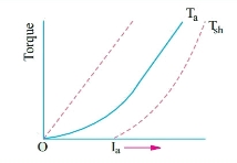
Fig: T v/s Ia characteristics
b) Speed and armature current characteristics: As we know speed (N) is related to back emf as
N α Eb/φ
But φ α Ia .
So, as the value of Ia increases the vale corresponding value of φ also increases. So, N αEb/ Ia
As the speed increases the value of current decreases (inversely proportional). For various values of load current there is very small change in the value of Eb, hence can be neglected here. The curve is shown below.
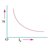
Fig: Speed verses Armature current characteristics
c) Speed and Torque characteristics: As Ta α φ Ia and φ α Ia , but N αEb/ Ia .So it can be easily concluded that speed and torque are inversely proportional. Hence when speed is high torque is low and vice versa. The curve is shown below.
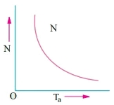
Fig: Speed verses Torque characteristics
DC Shunt
a) Torque and Armature current characteristics: As relation between torque and armature current is Ta α φ Ia , assuming φ to be practically constant. So, Ta α Ia and the characteristics are linear as shown below.
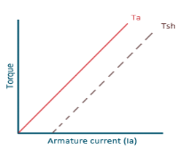
Fig: Torque versus Armature current
b) Speed and Armature current characteristics: N α Eb/φ , for φ to be practically constant N α Eb . But both Eb and φ decrease with increasing load. The drop varies from 5 to 15% of full load speed. As Eb decreases more than φ speed decreases.
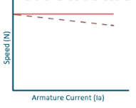
Fig: Speed verses Armature current characteristics
c) Speed and Torque Characteristics: From above to characteristics, curve for this shown below.
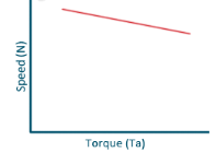
Fig: Speed verses Torque characteristics
Examples
Que) A 250V shunt motor on no load runs at 900rpm and takes 4amperes, armature and shunt field resistances are 0.2 and 250 ohms respectively. Calculate the speed when loaded taking current of 50A. The armature reactions weakens the field by 3%?
Sol: Ish=250/250=1A
Ia1=4-1=3A
Ia2=50-1=49A
Eb1=250-3*0.4=248.8V
Eb2=250-49*0.2=240.2A


N2=898rpm
Que) The speed of a 37.3kW series motor working on 500V supply is 600 rpm at full load and 90% efficiency. If the load torque is made 250 N-m and a 5ohm resistance is connected in series with the machine, calculate the speed at which the machine will run. Assume armature and field resistance of 0.5ohm?
Sol: Load torque in first case T1=37300/2 (600/60)=593.65 N-m
Input current Ia1=37300/0.9*500=82.9A
T2=250 N-m. So, finding Ia2
For series motor T α φ Ia α Ia2
T1 α  and T2 α

 =82.9*
 =53.79A
Eb1=500-(82.9*0.5)=458.5V
Eb2=500-53.79(5+0.5)=204.11V


D.C Motors
- Separately Excitation
It is the curve which relates the field current and armature terminal voltage on open circuit. For generating mode, we already know that generated emf is directly proportional to flux per pole and speed of armature.

The circuit is given below-
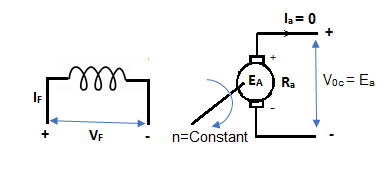
Fig: Separately Excited DC Motor
From above figure,
Voc = Ea
The magnetization characteristic of dc machines is determined by measuring Voc at rated armature speed and gradually increasing If from zero till Voc reaches above rated value of machine.
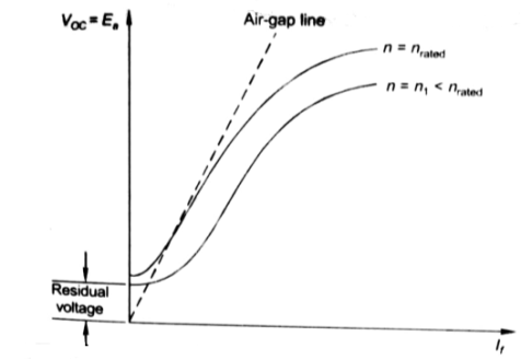
Fig: Speed current characteristic curve
From above curve, we can conclude
1) A small residue voltage is present when field is unexcited.
2) The field current If increases from initial value, the flux and hence generated emf is increased.
3) The air-gap line is the magnetic behaviour of machines air-gap. The iron being unsaturated in this region consumes negligible power.
4) The open circuit cost is conducted by exciting the main field winding.
5) The equivalent main field current is given

Nf, main field turns
If, main field current
Nse, main series turn
Ise, main series current
As induced emf is reduced by demagnetizing effect of armature reaction in saturation region of curve. So, the modified magnetization characteristics are shown below with Ia = 0, Ia = Ia1, Ia = Ia2.
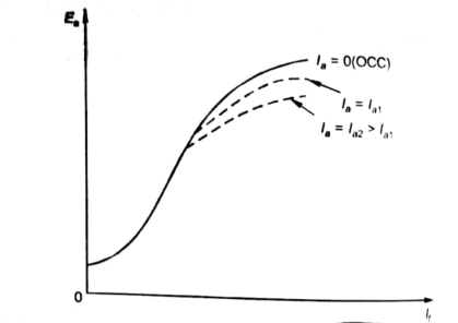
Fig: Armature reaction in Speed current characteristics
B. Self excitation
The magnetization curve relates the no load voltage to the field current. The circuit is shown below
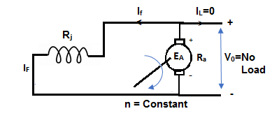
Fig: Self Excited DC motor
The field is introduced after the armature has been brought to rated speed. Just the moment after switching on the field, residue armature voltage exists which causes small value of field current. A fine steady state value is attained because of the saturation state of machines magnetic circuit. The magnetization curve is shown below:
The current in armature can be related to field current as
Ia = If
V = Ea- If Ra
In this case, field current is very small, so
V ≈ Ea (If) [magnetization characteristic]
For field current,
V = If Rf
- The intersection point P on Rf line gives the values of no-load voltage Vo and corresponding field current If.
- Vo can be adjusted by varying Rf.
- Further, the above plot can be assessed by keeping armature speed constant and varying Rf. The plot is shown below.
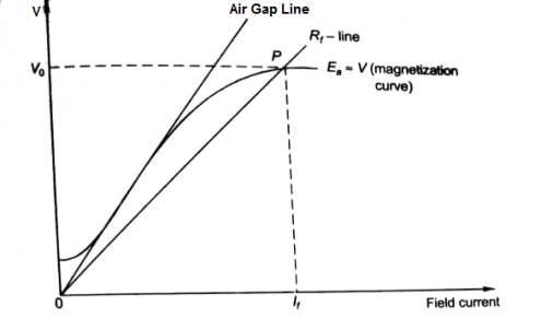
Fig: Magnetising Curve
- As Rf is increased, the value of Vo decreases.
- Value of Vo is not defined for (Rf3 = Rfc).
- As the value of field resistance here is increased to high value but does not produce high Vo, rather its value is close to residue voltage. Hence, machine field fails to excite and this value of resistance is called critical resistance Rc.
- Now keeping Rf fixed and varying armature speed, the plot is shown below:
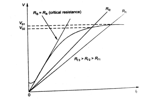
Fig: Characteristic curve with Rf fixed
- As the speed decreases, the open circuit characteristics also decrease proportionally.
- At critical Speed, the generator fails to excite.
All motors should be started with external resistance in armature circuit to limit the starting current to safe values, if not then there can be a risk of high value of torque which can cause mechanical shock to the shaft and it can also cause heavy sparking at the brushes which can damage the commutator and brush gear. At the time of starting the induced emf of motor is zero. In case of direct start of motor, the toque is much higher and motor starts quickly, which saves the energy and reduces temperature rise. Maximum allowable starting current cannot be more than 1.5 to 2.0 times the rated value. For variable speed the starting of motor has no problem.
The connection diagram of DC Shunt motor starter is shown below. It is the manual starter.
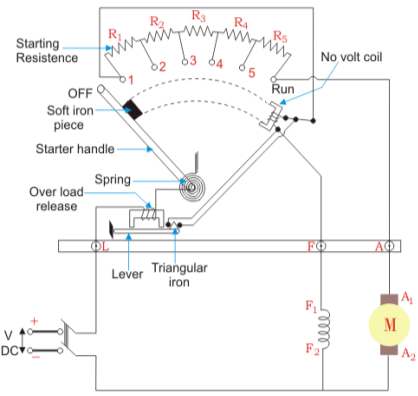
Fig: DC Shunt motor starter
In shunt motor starting to maintain high torque the starting resistance is arranged in steps. When starter is in ON position the starting resistance is cut out. The handle can go back to OFF position when there is no field current and in case of overload when the contact of relay at armature current is above certain value. Modern industries use push button type automatic starters. As shown in the figure below
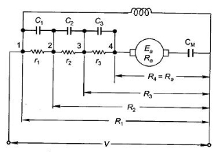
Fig: Shunt motor starting
They have automatic relays that short the section of starting resistors when the armature current has dropped to a pre-set value.
Calculation of starter step for DC Shunt Motor
From above figure when the stud is moved to point 1, the current I1 is reached.
I1 = V/R1
When the speed of motor increases the current decreases and the back emf rises. The value of current I2 is given as
I2=
 is back emf. The current I1 is given as


For k stud starter


Hence 
After calculating starter step
i)Find R1
Ii)Find number of steps k
Iii)Find R1, R2…….
Key takeaway
At the time of starting the induced emf of motor is zero. In case of direct start of motor, the toque is much higher and motor starts quickly, which saves the energy and reduces temperature rise.
Que) A starter required for a 220V shunt motor. The maximum allowable current is 45A and the maximum current is about 35A. Find the number of sections of starter resistance required and the resistance of each section. The armature resistance of motor is 0.4 ohm?
Sol: I1=45 A, I2=35 A
 =1.28
=1.28
R1=
As 

Let n=5
=1.825
As we already know 
R1=4.44Ω
R2=
R3=
r1= R1- R2=2.01
r2= R2- R3=1.1
Similarly, r3=0.60, r4=0.20 can be calculated.
A 3 point starter is used for starting a DC shunt motor. The starter is shown below
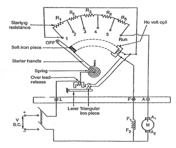
Fig: 3-point starter
The arm of stud is moved to 1, to start the motor. The complete resistance added to armature winding. Through No-volt-coil(NVC) the field winding also gets full supply. So the motor develops torque and starts rotating with full starting resistance. When the stud is moved further RUN position is achieved. In this position a soft iron piece is attached to starter arm. Therefore, will stay in the RUN position against the spring tension. In case of overload the armature winding will draw excess current and may get damaged. So, to protect from this damage the over load release coil will be short circuited and will demagnetise NVC. Which will eventually turn off DC motor.
Disadvantages of 3-point starter:
The field current is reduced when a large resistance is connected to increase the speed. But the field winding and NVC are connected in series, the current through NVC decreases. This may cause the starter to move to OFF position, which may effect the working of motor. To overcome this drawback we have four point starter.
Four point starter:
In this the NVC coil is connected independently across the supply voltage instead of connecting it in series with the motor field winding.
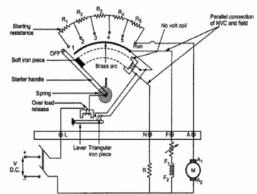
Fig: Four Point starter
When the arm is brought to position 1 current flows through armature winding, the field winding will also get full supply. In this the field winding and NVC are isolated from each other. Hence, any change in If will not affect NVC like in three point starter. When started arm is brought to the RUN position, the armature of the dc motor will run at its full speed and remain connected to the supply through the starter arm. In case of overload, the OLR terminal will be short circuited to the NVR coil to release the starter arm to the OFF position.
The speed control of DC motor is given by

The speed can be controlled by varying
i)Φ=flux/pole
Ii)Ra=Armature resistance
Iii)V=Applied voltage
For DC Series Motor: In DC Series motor speed control can be done in two ways:
i)Flux Control: In this there are four ways to control speed
a) Field Divertors
b) Armature Divertors
c) Trapped Field control field
d)Paralleling field coils
Ii) Variable resistance in series with motor
Firstly, discussing the Flux Control method to control speed in DC Series motor.
a) Field Divertors: In this one variable resistance in parallel to the field winding is connected. It is called as field divertor. We can control the current through the field divertor by adjusting its resistance. As we can control the current, the flux can also be decreased and hence the speed will increase. Below shows the figure.
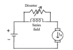
Fig: Field Divertor
b) Armature Divertor: In this the variation in speed can be controlled by varying the divertor resistance. As we know TaαφIa and Nα  . Hence if flux increases (as Ia can be reduced due to armature divertor) speed will decrease. The figure is shown below.
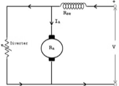
Fig: Armature Divertor
c)Trapped Field control field: In this the series field turns can be changed according to our wish. The speed can be increased by removing off some of the series turns. The figure is shown below.
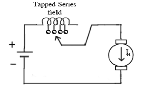
Fig: Trapped Field control field
d) Paralleling field coils: In this speed control can be done by regrouping the field coils.
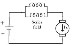
Fig: Paralleling of field coils
Ii) Variable resistance in series with motor: The voltage across armature can be reduced increasing the resistance in series with it. As the voltage reduces the speed also reduces. The below fig a shows the variable resistance across armature and fig b shows the variation of speed with respect to armature current.
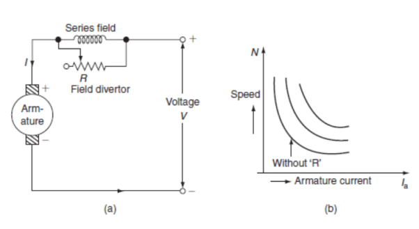
Fig: Circuit and characteristics of variable resistance in series with motor
For DC Shunt Motor: There are three basic methods to control the speed of DC Shunt motor listed below
i)Flux control method
Ii)Armature or Rheostatic control
Iii)Voltage control
i) Flux control method: As we already know that flux and speed for shunt motors are inversely proportional to each other. As the name suggests flux control which means we can control the flux and maintain required speed. The flux can be controlled by changing Ish with help of shunt field rheostat. The figure is shown below.
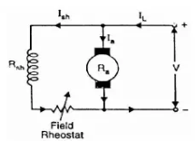
Fig: Flux control method
Ii) Armature or Rheostatic control: This is the most common method employed. In this the controlling resistance is connected directly in series with the supply of the motor. As resistance Ra is increased potential drop across armature decreases, and hence the speed too decreases. The figure is shown below.
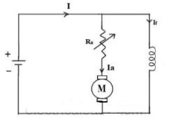
Fig: Armature control
One more to control speed here is shunting the armature and a rheostat in series with the armature is involved in this method of speed control. The voltage applied to the armature varies by varying series rheostat R1. The exciting current can be varied by varying the armature shunting resistance R2. This method of speed control is not economical due to considerable power losses in speed controlling resistances.
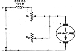
Fig: shunted armature speed control
Iii) Voltage control method: There are two ways in voltage control method
a) Multiple voltage control: In this method the shunt field of motor is connected permanently to a fixed exciting voltage, but armature is supplied with different voltages. The armature speed is approximately proportional to these different voltages. This method is not used now.
b) Ward-Leonard System: The figure below shows the ward-Leonard system. In this method speed of motor M1is controlled which is powered by generator G. The shunt field of motor is connected across DC supply. The motor M2derives the generator. When the output voltage of the generator is fed to the motor M1 then the motor starts to rotate. When the output voltage of the generator varies then the speed of the motor also varies. By controlling the output voltage of generator speed of motor can be controlled. To attain this a field regulator is connected across the generator. The direction of rotation of motor can be reversed by excitation current of generator, this will happen by reversing the switch R.S. The motor-generator should run in same direction.
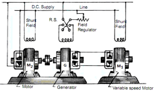
Fig: Ward Leonard System
Key takeaway
The speed can be controlled by varying
i)Φ=flux/pole
Ii)Ra=Armature resistance
Iii)V=Applied voltage
Que) A dc series motor drives a load torque of which varies as the square of the speed. The motor takes a current of 15A when speed is 500 rpm. Calculate the speed and the current when the motor field winding is shunted by a diverter of same resistance as that of the field winding.
Sol: As we already know TaαφIa and Nα 
Ta1 α 
Ta2 α 

Ta1 α φ1Ia1
Ta2 α φ2Ia2
As field current is half the armature current so 
 ………(1)

Neglecting armature and series winding drop.
 ………(2)
From 1 and 2


152=25.2A
From 2 we get N2=500*2*15/25.2=595.2 rpm
Que) A 200V dc shunt motor running at 900rpm takes an armature current of 15.5A. It is required to reduce the speed to 600 rpm. What must be the value of resistance to be inserted in the armature circuit if the original resistance is0.4Ω?
Sol: N1=900rpm
Eb1=200-15.5*0.4=193.8 V
N2=600rpm
Eb2=200-15.5*Rt
Rt= total armature circuit resistance
Assuming armature current constant. Φ1= Φ2

Rt=4.57 Ω
Additional resistance required=Rt-Ra=4.57-0.4=4.17 Ω
Ward Leonard Method of speed control is achieved by varying the applied voltage to the armature. This method was introduced in 1891. The connection diagram of the Ward Leonard method of speed control of a DC shunt motor is shown in the figure below.
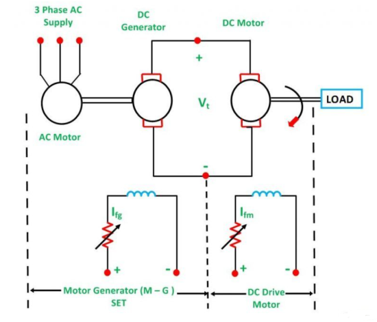
In the above system, M is the main DC motor whose speed is to be controlled, and G is a separately excited DC generator. The generator G is driven by a 3-phase driving motor which may be an induction motor or a synchronous motor.
The combination of an AC driving motor and the DC generator is called the Motor-Generator (M-G) set. The voltage of the generator is changed by changing the generator field current. This voltage when directly applied to the armature of the main DC motor, the speed of the motor M changes. The motor field current Ifm is kept constant so that the motor field flux ϕm also remains constant. While the speed of the motor is controlled, the motor armature current Ia is kept equal to its rated value.
The generated field current Ifg is varied such that the armature voltage Vt changes from zero to its rated value. The speed will change from zero to the base speed. Since the speed control is carried out with the rated current Ia and with the constant motor field flux, a constant torque is directly proportional to the armature current, and field flux up to rated speed is obtained. The product of torque and speed is known as power, and it is proportional to speed. Thus, with the increase in power, speed increases automatically.
The Torque and Power Characteristic is shown in the figure below:
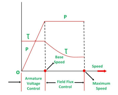
Hence, with the armature voltage control method, constant torque and variable power drive are obtained from speed below the base speed. The field flux control method is used when the speed is above the base speed. In this mode of operation, the armature current is maintained constant at its rated value, and the generator voltage Vt is kept constant.
The motor field current is decreased and as a result, the motor field flux also decreases. This means that the field is weakened to obtain higher speed. Since VtIa and EIa remain constant, the electromagnetic torque is directly proportional to the field flux ϕm and the armature current Ia. Thus, if the field flux of the motor is decreased the torque decreases. Therefore, the torque decreases, as the speed increases. Thus, in the field control mode, constant power and variable torque are obtained for speeds above the base speed. When the speed control over a wide range is required, a combination of armature voltage control and field flux control is used.
This combination permits the ratio of maximum to minimum speed available speeds to be 20 to 40. For closed-loop control, this range can be extended up to 200. The driving motor can be induction or synchronous motor. An induction motor operates at a lagging power factor. The synchronous motor may be operated at a leading power factor by over-excitation of its field. Leading reactive power is generated by an over-excited synchronous motor. It compensates for the lagging reactive power taken by other inductive loads. Thus, the power factor is improved.
A slip ring induction motor is used as p prime mover when the load is heavy and intermittent. A flywheel is mounted on the shaft of the motor. This scheme is known as Ward Leonard-Ilgener scheme. It prevents heavy fluctuations in supply current.
The back to back testing is one of the methods for testing the efficiency of the DC machine. It is a full load test and requires two identical machines which are coupled together. In these two one machines is operated as generator to supply mechanical power to the motor and other is operated as motor to drive the generator. This test is also called as Hopkinson’s Test. As there is drop in the generator output voltage, we need an extra voltage source to supply the required input voltage to motor. The output power from the external supply is used to overcome the internal losses of the motor-generator set.
A motor and a generator, both identical, are coupled together. When the machine is started it is started as motor. The shunt field resistance of the machine is adjusted so that the motor can run at its rated speed.
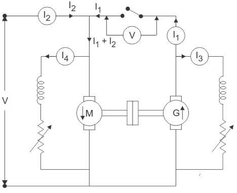
Fig: Circuit for back to back test
The generator voltage is now made equal to the supply voltage by adjusting the shunt field resistance connected across the generator. This equality of these two voltages of generator and supply is indicated by the voltmeter as it gives a zero reading at this point connected across the switch. The machine can run at rated speed and at desired load by varying the field currents of the motor and the generator.
Calculation of Efficiency by Hopkinson’s Test
Let V= supply voltage of machine
Motor input= V(I1+I2)
I1 = The current from the generator
I2 = The current from the external source
And, Generator output = VI1………………(1)
Let the efficiency of both the machines be 
The motor output will be =  x input=
  x V(I1+I2)
Output of motor = Input to generator=  x V(I1+I2)
Output of generator=  x input=
  x V(I1+I2)]=
 x V(I1+I2) ………….(2)
From (1) and (2)
VI1= x V(I1+I2)
I1= (I1+I2)
 =
= 
Armature copper loss in the motor =(I1+I2-I4)2Ra
Shunt field copper loss in the motor will be = VI4
Next, in case of generator armature copper loss in generator =(I1+I3)2Ra
Shunt field copper loss in the generator = VI3
Now, Power drawn from the external supply = VI2
Ra is the armature resistance of both motor and generator.
I4 is the shunt field current of the motor.
I3 is the shunt field current of the generator.
Therefore, the stray losses in both machines will be
W=VI2-(I1+I2-I4)Ra+VI4+(I1+I3)2Ra+VI3
If Stray losses are same for both the machines= W/2
Efficiency of Generator
WG=(I1+I3)2Ra+VI3+
Total losses in the generator,
Generator output = VI1
The generator efficiency is
 =
= =
= =
=
Efficiency of Motor
WM=(I1+I2-I4)2Ra+VI4+
Total losses in the motor,
Motor Input= V(I1+I2)
Then, efficiency of the motor,
 =
= =
= =
=
Advantages of Hopkinson’s Test
- This test requires very small power compared to full-load power of the motor-generator coupled system. That is why it is economical. Large machines can be tested at rated load without much power consumption.
- Temperature rise and commutation can be observed and maintained in the limit because this test is done under full load condition.
- Change in iron loss due to flux distortion can be taken into account due to the advantage of its full load condition.
- Efficiency at different loads can be determined.
Disadvantages of Hopkinson’s Test
The demerits of this test are
- It is difficult to find two identical machines needed for Hopkinson’s test.
- Both machines cannot be loaded equally all the time.
- It is not possible to get separate iron losses for the two machines though they are different because of their excitations.
- It is difficult to operate the machines at rated speed because field currents vary widely.
Que) The Hopkin’s test on two similar shunt machines gave the following Full load data. Line voltage = 110 V; Line current = 48 A; Motor armature current = 230 A; Field currents are 3 A and 3.5 A; Armature resistance of each machine is 0.035 Ω; brush drop of 1V/brush; Calculate the efficiency of each machine.
Sol: Motor:
Armature copper loss = (230)2 x 0.035 = 1851.5 W
Brush contact loss = 230 X 2 = 460 W
Total armature copper loss = 1851.5 + 460 = 2312 W
Shunt field copper loss = 110 X 3 = 330 W
Total copper loss = 2312 + 330 = 2642 W
Generator:
Generator armature copper loss = (188.5)2 x 0.035 = 1244 W
Brush contact loss = 188.5 X 2 = 377 W
Total armature copper loss = 1244 + 377 = 1621 W.
Shunt field copper loss = 110 X 3.5 = 385 W
Therefore, total copper loss = 1621 + 385 = 2006 W
Total copper loss for set = 2642 + 2006 = 4648 W
Total input = 110 X 48 = 5280 W
Therefore, stray losses = 5280 – 4648 = 632 W
Stray losses/machine =632/2=316
Total losses = 2312 + 330 + 316 = 2.958 kW
Motor input = 110 X 233 = 25.630 kW.
Motor output = 22.672 kW
 =
= =
= =88.45%
Generator total losses = 1621 + 385 +316 = 2.322 kW
Output of generator = 110 X 185 = 20.350 kW
 =
= =
= =89.4%
Que) In a Hopkinson test on 250 V machine, the line current was 50 A and the motor current is 400 A not including the field currents of 6 and 5 A. The armature resistance of each machine was 0.015Ω. Calculate the efficiency of each machine.
Sol: Motor armature copper loss = (400)2 X 0.015 = 2400 W
Generator armature copper loss = (350)2 X 0.015 = 1838 W
Input power = 250 X 50 = 12500 W
Ws stray losses = 12500 – (2400 + 1838) = 8262 W;
Ws per machine = 8262/2=4130
Motor efficiency:
Armature copper loss of motor = 2400 W;
Motor field copper loss = 250 X 5 = 1250 W
Total motor losses = 2400 + 1250 + 4130 = 7780 W
Motor input = 250 X 400 + 250 X 5 = 101250 W.
Therefore η = =
= = 92.3 %
Generator efficiency:
Generator armature copper loss = 1838 W
Generator field copper loss = 250 X 6 = 1500 W
Total losses of Generator = 1828 + 1500 + 4130 = 7468 W
Generator Output = 250 X 350 = 87500 W
Efficiency of Generator =  =
= =
= = 91.5%
References:
1. Chapman, S. J. 1999. Electric Machinery Fundamentals. New York: McGraw-Hill.
2. Clayton, A. E. And N. H. Hancock 1962. Performance and Design of DC Machines. London: ELBS Pitman Edn.
3. Dorf, R. C. 1993. The Electrical Engineering Handbook. Boca Raton, Florida, 33431: CRC Press.
4. Draper, A. 1967. Electric Machines. London: Longman.
5. Elgerd, O. 1982. Electric Energy System Theory: An Introduction. New York: McGraw-Hill.