Unit - 2
Electrostatic fields
According to this law, the force of interaction between any two point charges is directly proportional to the product of the charges and inversely proportional to the square of the distance between them.
Suppose two bodies having charges  are separated in vacuum by distance r. Their linear dimensions be much smaller than the distance r so that they act as point charges.
According to coulomb’s law


Where k is electrostatic force constant if  i.e. both the charges
  are positive or both are negative, bodies repel each other as shown in figure 1 (a).
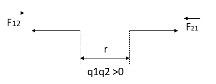
Let,  = force on
  due to
  and
and , unit vector pointing from
According to coulomb’s law

K is electrostatic force constant similarly the force on q due to 

Pointing from 
If  if one of the charges is positive and other is negative, the bodies attract each other, figure 1 (b)
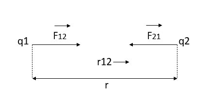


This shows that the force exerted by the two charges on each other are equal and opposite. Coulomb’s law is valid only for point charges.
The value of electrostatic force constant depends on the nature of medium separating the charges and on the system of units. When charges are situated in free space (air/vacuum) then CGS system K=1
In SI we write

Where is called absolute electric permeability of the free space.
The experimentally measured value of K is 
Therefore


From equation 1 we can re write coulombs law in SI unit

The magnitude force is

Solved Examples
Q1. Two insulated charged copper spheres A and B half their centres separated by 50 cm. What is the mutual force of repulsion if charge on each is  coulomb? The radii of A and B is negligible compared to distance of separation.
B) What is the force of repulsion of each sphere is charged double of the above amount and the distance between them is halved?
Sol. 


B) 


Q2. The electrostatic force on a small sphere of charge 0.4μc due to another small sphere of charge -0.8μc in air is 0.2 N.
(a) What is the distance between the two spheres?
(b) What is the force on the second sphere due to the first?
Sol. Here,


B) Force on second sphere is same 0.2N=F
Q3. A point charge of 2.0 μc is at the centre of a cubic Gaussian surface 90 cm on edge. What is the electric flux through the surface?
Sol. Here q= 20 μc=2×
L=90 cm
 =
= 

Q4. Consider uniform electric field E, 
Field is along positive x direction
Surface area =
(a)What is the flux of this field through a square of 10 cm on a side whose plane is parallel to y z plane?
(b)What is the flux through the same square is the normal to its plane 30 degree angle with x axis?
Sol.(a) When plane is parallel to y z plane


(b)When normal to the plane makes an angle of 30 degree with x-axis then  =30°
=30°


Q5. Two particles having charges  and
and  coulombs are spaced 0.8 metre apart. Determine the electric field at a point A situated at a distance of 0.5 metre from each of the particles.
Sol. Let the two particles have charge  coulombs then the point A will be as shown in (1). Let the origin of the three axis be located at the point charge
  then the coordinates of
  will be (0,0) (0.8,0) respectively.


Differentiating partially with respect to x and y we get


For the location of point A
x=0.4 and y=  =0.3
=0.3
Substituting these values we have


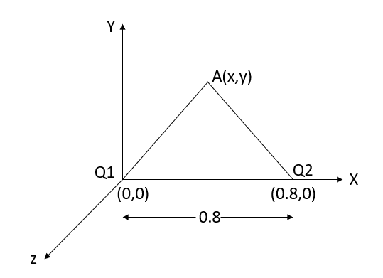


Since the field is desired in xy plane
 and field intensity E is given by

Substituting the values of  and
and  we get

We have seen so far, the charge distributions have been discrete i.e. made up of individual point particles.
If a charge distribution is continuous rather than discrete, we can generalize the definition of the electric field. We simply divide the charge into infinitesimal pieces and treat each piece as a point charge.
We know that charge is quantized so there is no such thing as a truly continuous charge distribution. However, in most practical cases, the total charge creating the field involves such a huge number of discrete charges.
For simplicity we can safely ignore the discrete nature of the charge and consider it to be continuous. This is exactly the kind of approximation we make when we deal with a bucket of water as a continuous fluid rather than a collection of H2O molecules.
Continuous charge distribution: an arrangement of many discrete charges so closely spaced that the charge is treated as a continuum, resulting in a replacement of discrete sums with integrals.
Distribution of charges
(a) Line charge density
(b) Surface charge density
(c) Volume charge density
(d) Some of the components of the total electric field cancel out, with the remainder resulting in a net electric field
Definitions of charge density:
(a) λ - Line charge: charge per unit length (linear charge density); units are coulombs per meter (C/m)
(b) - Surface charge density: Charge per unit area; units are coulombs per square meter (C/m2)
(c) - Volume charge density: Charge per unit volume; units are coulombs per cubic meter (C/m3)
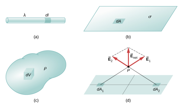
Figure: Charge Distribution
Some of the important result for electric field due to point charge, line charge density, surface charge density and volume charge density.
Point charge: 
Line charge: 
Surface charge: 
Volume charge: 
Note carefully the meaning of r in these equations: It is the distance from the charge element λdl, ds, dV to the location of interest, P(x,y,z) (the point in space where you want to determine the field). However, don’t confuse this with the meaning of 
ELECTRIC FIELD AND ELECTROSTATIC POTENTIAL FOR A CONTINUOUS CHARGE DISTRIBUTION
If the charge distribution is continuous, the potential at a point P can be found by summing over the contributions from individual differential elements of charge. Dq
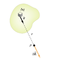
Figure: Continuous charge distribution
Consider the charge distribution shown in Figure. Taking infinity as our reference point with zero potential, the electric potential at P due to dq is

Summing over contributions from all differential elements, we have

We established the relation between  and V. If we consider two points which are separated by a small distance
 , the following differential form is obtained.

In Cartesian coordinates,

And 


This implies

By introducing a differential quantity called the “del (gradient) operator”

The electric field can be written as


Notice that ∇ operates on a scalar quantity (electric potential) and results in a vector quantity (electric field). Mathematically, we can think of  as the negative of the gradient of the electric potential V. Physically, the negative sign implies that if V increases as a positive charge moves along some direction, say x, with , then there is a non-vanishing component of
  in the opposite direction(-
 )
)
In the case of gravity, if the gravitational potential increases when a mass is lifted a distance h, the gravitational force must be downward.
If the charge distribution possesses spherical symmetry, then the resulting electric field is a function of the radial distance r, i.e. 
In this case, 
If V(r) is known, then  may be obtained as

For example, the electric potential due to a point charge q is

Using the above formula, the electric field is simply

ELECTRIC FIELD OF A LINE SEGMENT OR ROD
Let us find the electric field a distance z above the midpoint of a straight-line segment of length L that carries a uniform line charge density λ.
Since this is a continuous charge distribution, we conceptually break the wire segment into differential pieces of length dl, each of which carries a differential amount of charge dq = λdl.
We proceed as follow to obtain the complete electric field expression.
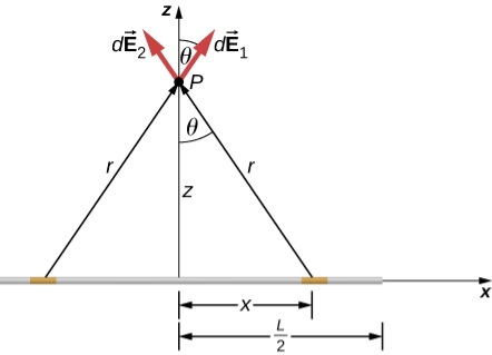
Figure: A uniformly charged segment of wire. The electric field at point P can be found by applying the superposition principle to symmetrically placed charge elements and integrating.
Since it is a finite line segment, from far away, it should look like a point charge. We will check the expression we get to see if it meets this expectation.
The electric field for a line charge is given by the general expression
 …………..(1)
The symmetry of the situation (our choice of the two identical differential pieces of charge) implies the horizontal (x)-components of the field cancel, so that the net field points in the direction. Let’s check this formally.
The total field  is the vector sum of the fields from each of the two charge elements are E1 and E2.
 …………..(2)
Because the two charge elements are identical and are the same distance away from the point P where we want to calculate the field,  , so those components cancel. This leaves
 …………..(3)
These components are also equal, so we have

 …………..(4)
Here our differential line element dl is dx, in this example, since we are integrating along a line of charge that lies on the x-axis.
The limits of integration are 0 to  , not
, not  to L, because we have constructed the net field from two differential pieces of charge dq. If we integrated along the entire length, we would pick up an erroneous factor of 2.
In principle, this is complete. However, to actually calculate this integral, we need to eliminate all the variables that are not given. In this case, both r and θ change as we integrate outward to the end of the line charge, so those are the variables to get rid of as follow

And  …………..(5)
Substituting, we obtain


 …………..(6)
This simplifies to
 …………..(7)
With the use of symmetry, we are able to find electric field due to line element. This is a very common strategy for calculating electric fields. The fields of non-symmetrical charge distributions have to be handled with multiple integrals.
ELECTRIC FIELD OF AN INFINITE LINE OF CHARGE
Find the electric field a distance z above the midpoint of an infinite line of charge that carries a uniform line charge density λ.
This is exactly like the article except the limits of integration will be - to +
Again, the horizontal components cancel out, so we wind up with

Where our differential line element dl is dx, in this example, since we are integrating along a line of charge that lies on the x-axis. Again,

Substituting, we obtain


This simplifies to

In the case of a finite line of charge, note that for z >>L, z2 dominates L in the denominator, so that Equation simplifies to

If you recall that λL=q, the total charge on the wire, we have retrieved the expression for the field of a point charge, as expected.
In the limit L , on the other hand, we get the field of an infinite straight wire, which is a straight wire whose length is much, much greater than either of its other dimensions, and also much, much greater than the distance at which the field is to be calculated:

ELECTRIC FIELD DUE TO A RING OF CHARGE
A ring has a uniform charge density λ, with units of coulomb per unit meter of arc. Find the electric potential at a point on the axis passing through the center of the ring.
We use the same procedure as for the charged wire. The difference here is that the charge is distributed on a circle. We divide the circle into infinitesimal elements shaped as arcs on the circle and use polar coordinates shown in figure.
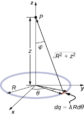
Figure: The system and variable for calculating the electric field due to a ring of charge.

 …………..(1)
A general element of the arc between θ and dθ is of length Rdθ and therefore contains a charge equal to λRdθ. The element is at a distance of r =  from P, the angle is ,
  and therefore, the electric field is


Significance
As usual, symmetry simplified this problem, in this particular case resulting in a trivial integral. Also, when we take the limit of Z >> R, we find that

ELECTRIC POTENTIAL FOR UNIFORMLY CHARGED ROD
Electric Potential
Electric potential is the work done by an applied force on a unit charge bringing it from infinity to a specific point. The work done is called electric Potential.
Consider a non-conducting rod of length A having a uniform charge density λ. Find the electric potential at P, a perpendicular distance y above the midpoint of the rod.
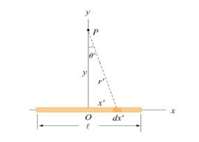
Figure: A non-conducting rod of length l and uniform charge density λ
Consider a differential element of length dx′ which carries a charge dq =λdx′, as shown in Figure. The source element is located at (x′,0) while the field point P is located on the y-axis at (0,y). The distance from dx′ to P is r =  . Its contribution to the potential is given by

Taking V to be zero at infinity, the total potential due to the entire rod is

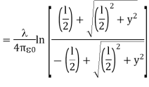
Where we have used the integration formula

In the limit the potential becomes l>>y


The corresponding electric field can be obtained as

ELECTRIC POTENTIAL FOR UNIFORMLY CHARGED RING
Uniformly consider a uniformly charged ring of radius R and charge density λ. Electric potential at a distance z from the central axis
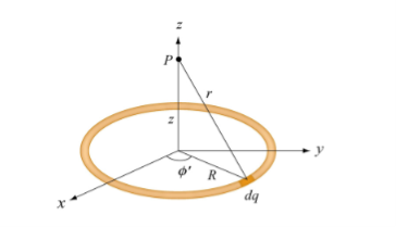
Figure: A non-conducting ring of radius R with uniform charge density λ
Consider a small differential element dl= Rd on the ring. The element carries a charge
Dq =λdl = λRd ………….(1)
And its contribution to the electric potential at P is

The electric potential at P due to the entire ring is
 ………….(2)
Where we have substituted Q=2πRλ for the total charge on the ring. In the limit z>>R, the potential approaches its “point-charge” limit:

From Equation 2, the z-component of the electric field may be obtained as

This is in agreement with the result of article 1.14
Key Takeaways
- Continuous charge distribution: an arrangement of many discrete charges so closely spaced that the charge is treated as a continuum, resulting in a replacement of discrete sums with integrals.
- Distribution of charges can be Line charge density, Surface charge density and Volume charge density
- Electric field for a continuous charge distribution can be written as

- Electric field of a line segment or rod is given by

5. Electric field of an infinite line of charge

6. Electric field due to a ring of charge

7. Electric potential is the work done by an applied force on a unit charge bringing it from infinity to a specific point. The work done is called electric Potential.
The region in which the influence of an electric charge can be felt is known as electric field. The force experienced by a unit positive charge at a point is called is electric field strength.
E= F/q N/C or V/m
Electric flux density is defined as the amount of flux passes through unit surface area in the space at right angle to the direction of electric field.
E = 
Q: charge
r: distance between the object and field
Definition:
The electric flux passing through any closed surface is equal to the total charge enclosed by that surface.
The total charge enclosed by the irregular closed surface is Q coulombs. Hence the total flux has to pass through the closed surface is Q. Consider a small differential surface dS at point P. As the surface is irregular the direction of D as well as its magnitude is going from point to point on the surface. The surface dS under consideration can be represented in vector form.

Where  to the surface dS at point P
The flux density at point P is D and its direction is such that it makes an angle Ѳ with the normal direction at point P.
The flux d passing through the surface dS is the product of the component normal to dS and d
 .
.
Mathematically this can be represented as,

Where  Component of
  in the direction of normal to the surface dS
From fig. 3.9 we can write


From the definition of the dot product

We can write


This is the flux passing through incremental surface area dS. Hence the total flux passing through the entire closed surface is to be obtained by finding the surface integration of the equation (5)

 sign indicates the integration over the closed surface is called closed surface integral.
Such a closed surface over which the integration in eq (6) is carried out is called Gaussian surface.
Total charge enclosed by the surface is given by

Applications:
Infinite line charge:
Consider an infinite line charge of density  C/m lying along the z-axis from -
  to
to  as shown in figure.
Consider the Gaussian surface as the right circular cylinder with z-axis as its axis and radius r as shown in figure. The length of the cylinder is L.
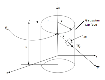
Infinite Line charge
The flux density at any point on the surface is directed radially towards that is in the  direction according to cylindrical co-ordinate system.
Consider differential surface area dS as shown which is at a radial distance r from the line charge. The direction is normal to dS is 
As the line charge is along z-axis there cannot be any component D in z direction. So, D has only radial component.

The integration is to be evaluated for side surface, top surface and bottom surface.

Now  as has only radial component
And  normal to
  direction.
 … as
… as 
Now  is constant over the side surface.
As  has only radial component and no component along
  and
and  hence integrations over top and bottom surfaces is zero.


And 
The results are same as obtained from the Coulomb’s law.
1. Gauss's law states that the total electric flux  through any closed surface is equal to the total charge enclosed by that surface.
Thus  = Qenc
That is

=total charge enclosed Q=

By applying the Divergence Theorem to the middle term, we get

If we compare the two volume integrals above:
 =
= 
Which is Maxwell’s First equation of Electrostatics.
2. The potential difference between points A and B is independent of the path taken.
Also, VBA = -VAB that is VBA + VAB =  = 0
= 0
Or

This shows that the line integral of electric field along a closed path must be zero. Physically, this implies that no work is done in moving a charge along a closed path in an electrostatic field. By applying Stoke’s Theorem


This is Maxwell’s Second equation of Electrostatics.
An electric dipole is formed when two point charges of equal magnitude but opposite sign is separated by a small distance.
Consider the dipole shown in Figure:
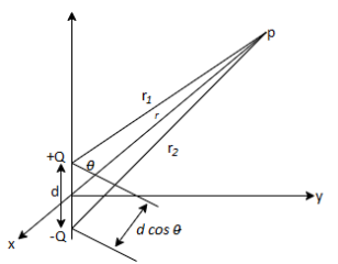
Figure: An electric dipole
The potential at point (r, is given by:
 …….(1)
Where r1 and r2 are the distances between P and + Q and P and -Q, respectively. If r >> d, r2 - r1 d cos (
 ), r2r1
 r2, and eq. (1) becomes
 ……….....(2)
Since d cos( ) = d.aR, where d=daZ, if we define
p=Qd
As the dipole moment, then eq.2 can be written as:
 ……..(3)
The dipole moment p is directed from -Q to + Q. If the dipole center is not at the origin but at r', eq.(3) becomes:
 ………………..(4)
The electric field due to the dipole with center at the origin, shown in Figure, can be obtained readily as:
 ……………....(5)

Where p = |p|= Qd
We notice that a point charge is a monopole and its Electric Field varies inversely as r2 and its potential varies inversely as r. We notice that the electric field due to a dipole varies inversely as r3, while its potential varies inversely as r2. The electric fields due to successive higher-order multipoles vary inversely as r4, r5, r6, ..., while their corresponding potentials vary inversely as r3, r4, r5,.. .
The rate of flow of electric field through given area is called as electric flux. If the electric field is uniform, the electric flux passing through a surface of vector area S is ΦE=E⋅S=EScosθ where E is the magnitude of the electric field (having units of V/m), S is the area of the surface, and θ is the angle between the electric field lines and the normal (perpendicular) to S.
For a non-uniform electric field, the electric flux dΦE through a small surface area dS are given by dΦE= E⋅dS (the electric field, E, multiplied by the component of area perpendicular to the field).
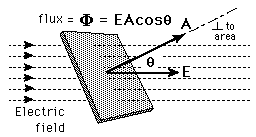
It is important to note that while the electric flux is not affected by charges that are not within the closed surface, the net electric field, E, in the Gauss’ Law equation, can be affected by charges that lie outside the closed surface. While Gauss’ Law holds for all situations, it is only useful for “by hand” calculations when high degrees of symmetry exist in the electric field. Examples include spherical and cylindrical symmetry.
Electric flux has SI units of volt metres (V m), or, equivalently, newton metres squared per coulomb (N m2 C−1). Thus, the SI base units of electric flux are kg·m3·s−3·A−1.
Key Takeaway
- If the electric field is uniform, the electric flux passing through a surface of vector area S is ΦE= E⋅S=ES cosθ.
- For a non-uniform electric field, the electric flux is.
- Electrical flux has SI units of volt metres (V m).
Energy density is the amount of energy stored in each system or region of space per unit mass. Only the useful or extractable energy is quantified which is to say that chemically inaccessible energy such as rest mass energy is ignored. Consider a point charge Q1 transferred from infinity to position r1 in the system. It takes no work to bring the first charge from infinity since there is no electric field to fight against as the system is charge free.
W1=0 J
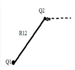
Now bring in another point charge Q1 from infinity to position r2 in the system. In this case we have do work against the electric field generated by the first charge Q1
W2 = Q1V21
V21= electrostatic potential at point r2 due to Q1
Work done now becomes
W2 = 
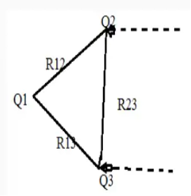
The work done required to bring Q3 to a distance R13 from Q1 and distance R23 from Q2 is
W3 = Q1 V31 +Q1 V32= Q1 (V31+V32)
V31 and V32 = electrostatic potential at point r3 due to Q1 and Q2 respectively.
The work done is simply the sum of the work done against the electric field generated by point charge Q1 and Q2 taken in isolation.
W3 = 
Thus, the total work done in assembling the three charges is given as
Wt=W1+W2+W3
Wt=0+Q2V21+Q3(V31+V32)
The total work done WE is given as
WE = 
If charges are positioned in reverse order, then the total work done is assembling them is given as
Wt=W3+W2+W1
Wt=0+Q2V23+Q3(V12+V13)
V31 and V32 = electrostatic potential at point r3 due to Q1 and Q2 respectively.
V23 = electrostatic potential due to r2 due to Q3
Adding above to equations
Wt= Q1(V12+V13) + Q2(V21+V23) +Q3(V31+V32) = Q1V1 + Q2V2 +Q3V3
Wt = 
V1, V2 and V3 = Potentials at position r1, r2 and r3
Energy for N point charges is
WE = 
The above equation means
a) This equation represents the potential energy of the system.
b) This is the work done in bringing the static charges from infinity and assembling them in the required system.
c) This is the kinetic energy which would be released if the system gets dissolved which means the charges returns to infinity.
For continuous charge density the line surface and volume charge will be given as
 (Line Charge)
 (Surface Charge)
 (Volume Charge)
Since  v=
v= 
And E= - 
Substituting in above equation the work done in assembling a volume charge distribution in terms of electric field and flux density will be
WE = 
This equation gives us the potential energy of a continuous charge distribution stored in an electric field.
The electrostatic energy density is given by
WE = 
The propagation of electromagnetic waves is a consequence of form of Maxwells equations. One form in which these equations can be written for free space is


In these expressions E and B are the electric and magnetic field vectors respectively of the wave and  o and µo are electric permittivity and magnetic permeability of free space.
It can be easily confirmed that the plane wave


Satisfies the equations that provided that the wave speed.
c = speed of light and of all electromagnetic waves in free space. It has a value of 2.99792458 x 10 8 m/s.
Conductors:
Figure shows the effect of an electric field on free charges in a conductor. The free charges move until the field is perpendicular to the conductor’s surface. There can be no component of the field parallel to the surface in electrostatic equilibrium, since, if there were, it would produce further movement of charge. A positive free charge is shown, but free charges can be either positive or negative and are, in fact, negative in metals. The motion of a positive charge is equivalent to the motion of a negative charge in the opposite direction.
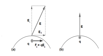
When an electric field E is applied to a conductor, free charges inside the conductor move until the field is perpendicular to the surface. (a) The electric field is a vector quantity, with both parallel and perpendicular components. The parallel component (E∥) exerts a force (F∥) on the free charge q, which moves the charge until F∥=0. (b) The resulting field is perpendicular to the surface. The free charge has been brought to the conductor’s surface, leaving electrostatic forces in equilibrium.
A conductor placed in an electric field will be polarized. Figure shows the result of placing a neutral conductor in an originally uniform electric field. The field becomes stronger near the conductor but entirely disappears inside it.
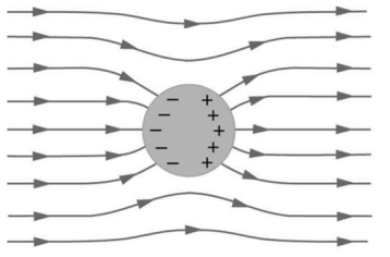
This illustration shows a spherical conductor in static equilibrium with an originally uniform electric field. Free charges move within the conductor, polarizing it, until the electric field lines are perpendicular to the surface. The field lines end on excess negative charge on one section of the surface and begin again on excess positive charge on the opposite side. No electric field exists inside the conductor since free charges in the conductor would continue moving in response to any field until it was neutralized.
Dielectric
When a dielectric material is placed in an electric field, electric charges do not flow through the material as they do in an electrical conductor but only slightly shift from their average equilibrium positions causing dielectric polarization.
To understand polarization, consider an atom of a dielectric. This consists of nucleus with positive and negative charge in the form of revolving electrons in the orbits. The negative charges are in the form of cloud of electrons.
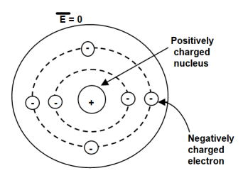
Figure. Unpolarized atom of a dielectric
The number of positive charges is same as negative charges and hence atom is electrically neutral. Due to symmetry both positive and negative charges are assumed to be point charges of equal amount coinciding at the centre. This is called unpolarized atom.
When electric field  is applied symmetrical distribution of charges gets disturbed. The positive charges experience a force
  while the negative charges experience a force -
  in opposite direction.
The separation between the nucleus and centre of atom is shown. Such an atom is polarized atom.
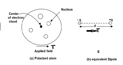
Figure. Polarized atom.
Expression:
When dipole is formed due to polarization there exists an electric dipole moment p.
 ----------------------(1)
Where
Q= magnitude of one of the two charges.
 = Distance vector from negative to positive charge.
Let n= Number of dipoles per unit volume
v=Total volume of the dielectric
N=Total dipoles=nv
The the total dipole moment to be obtained using superposition principle as,
 ---------------(2)
If dipoles are randomly oriented  is zero but if dipoles are aligned in the direction of applied E then
  has significant value.
The polarization  is defined as the total dipole moment per unit volume

It is measured in coulombs per square (C/ )
)
------------------------(3)
It can be seen that the units of polarization are same as that of flux density  . Thus polarization increases the electric flux density in a dielectric medium. Hence we can write flux density in a dielectric is,
 (4)
(4)
For isotropic and linear medium the  are parallel to each other at every point and related to each other as,
 (5)
(5)
Where  Dimensionless quantity called electric susceptibility of the material
The susceptibility tells us how sensitive is a given dielectric to the applied electric field 
Substituting (5) in (4)

 (6)
(6)
 (7)
(7)
 (8)
(8)
The quantity  is defined as relative permittivity or dielectric constant of the dielectric material.
 (9)
(9)
When there is presence of some mechanical force which tends the charge particles to move but they are also opposed by the electric field results in some current flow called as convection current.
The movement of charged particle due to electric field and not due to any ither surrounding material is called as conduction current. In some materials, the electric field is also able to dislodge weakly-bound electrons from atoms, which then subsequently travel some distance before reassociating with other atoms. For this reason, the individual electrons in a conduction current do not necessarily travel the full distance over which the current is perceived to exist.
Conduction | Convection |
In conduction The heat transfer takes place between objects by direct contact. | In convection, The heat transfer takes within the fluid. |
The heat transfer takes place due to the difference in temperatures. | The heat transfer due to the difference in density. |
The heat transfer in conduction is slow | The heat transfer in convection is faster. |
The heat transfer occurs through a heated solid object. | The heat transfer occurs through intermediate objects. For example heat transfer between air and water. |
It does not follow the law of reflection and refraction | It does not follow the law of reflection and refraction |
A conductor has an abundance of charge that is free to move. Let us consider an example, in the figure below. When an external Electric Field Ee is applied, the positive free charges are pushed along the same direction as that of the field and the negative free charges move in the opposite direction. This charge migration takes place very quickly. The free charges first accumulate on the surface of the conductor and form an induced surface charge. Then the induced charges set up an induced internal Electric Field Ei, which cancels the externally applied Electric field Ee. This leads to an important property of a conductor:
A perfect conductor ( ) cannot contain an electrostatic field within it.
A conductor is called an equipotential body which means that potential is same everywhere in the conductor. This is because E = - = 0.
= 0.
Under static conditions,
E=0,  = 0, Vab = 0 inside a conductor.
Where Vab is the potential difference between points a and b in the conductor.
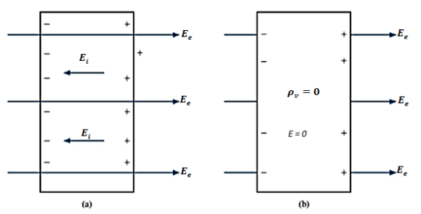
Figure: (a) An isolated conductor under the influence of an applied field. (b) A conductor has zero electric field under static conditions.
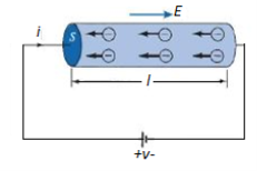
Figure: A cylindrical conductor at Potential V
We now consider a conductor whose ends are maintained at a potential difference V, as shown in Figure. In this case, E  0 inside the conductor. Since there is no static equilibrium in Figure and the conductor is not isolated but is wired to a source of electromotive force, which compels the free charges to move and prevents the eventual establishment of electrostatic equilibrium. Thus, in this case an electric field must exist inside the conductor to sustain the flow of current.
As the electrons move, they encounter some damping forces called resistance. Based on Ohm's law the resistance of the conducting material is determined.
We assume the conductor has a uniform cross section of area A and is of length l. The direction of the electric field E produced is the same as the direction of the flow of positive charges or current I. This direction is opposite to the direction of the flow of electrons. The electric field applied is uniform and its magnitude is given by:
E =  ….(1)
….(1)
Since the conductor has a uniform cross section,
 ….(2)
….(2)
 ……(3)
……(3)
Hence,  ………(4)
 ……(5)
……(5)
Where  , the resistivity of the conductor. Eq. 5 is used in determining the resistance of the conductor when area of cross-section is uniform.
To understand polarization, consider an atom of a dielectric. This consists of nucleus with positive and negative charge in the form of revolving electrons in the orbits. The negative charges are in the form of cloud of electrons.
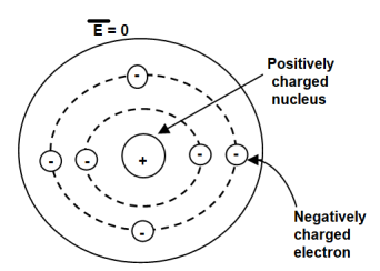
Figure. Unpolarized atom of a dielectric
The number of positive charges is same as negative charges and hence atom is electrically neutral. Due to symmetry both positive and negative charges are assumed to be point charges of equal amount coinciding at the centre. This is called unpolarized atom.
When electric field  is applied symmetrical distribution of charges gets disturbed. The positive charges experience a force
  while the negative charges experience a force -
  in opposite direction.
The separation between the nucleus and centre of atom is shown. Such an atom is polarized atom.
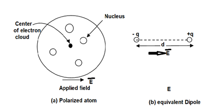
Figure. Polarized atom.
Expression:
When dipole is formed due to polarization there exists an electric dipole moment p.
 ----------------------(1)
Where
Q= magnitude of one of the two charges.
 = Distance vector from negative to positive charge.
Let
 Number of dipoles per unit volume
 Total volume of the dielectric
N= Total dipoles=n v
Then the total dipole moment is to be obtained using super position principle as,
 ----------------(2)
If dipoles are randomly oriented  is zero but if dipoles are aligned in the direction of applied E then has significant value.
The polarization  is defined as the total dipole moment per unit volume.

It is measured in coulombs per square meter (C/
------------------------(3)
It can be seen that the units of polarization are same as that of flux density  Thus polarization increases the electric flux density in a dielectric medium. Hence, we can write, flux density in dielectric is,

For isotropic and linear medium, the  and
and  are parallel to each other at every point and related to each other as,

Where  Dimensionless quantity called electric susceptibility of the material.
The susceptibility tells us how sensitive is a given dielectric to the applied electric field 
Substituting (5) in (4)


The quantity  is defined as relative permittivity or dielectric constant of the dielectric material

- The electric field applied to dielectric increases sufficiently due to force exerted on the molecules the electrons in the dielectric becomes free.
- Due to large electric field the dielectric field becomes conducting due to presence of large number of free electrons. This condition of dielectric is called dielectric breakdown.
- All kinds of dielectric such as solids, liquids and gases show the tendency of breakdown under large electric field. The breakdown depends on the nature of the material, time and magnitude of applied electric field and atmosphere conditions such as temperature, moisture, humidity etc.
- Once breakdown occurs dielectric starts conducting and no longer behave as dielectric. Hence, dielectric is assumed to be ideal or not in breakdown condition.
Q. Find the magnitude of  and
and  for a dielectric material in which
  and
and 
Sol:
For dielectric medium

Where  xe +1 = 4.25 + 1= 5.25
 = 8.854 x 10 -12 x 5.25 x 0.15 x 10 -3
= 6.9725 x 10 -15 C/m2
And

|  | = 4.25 x 8.854 x 10 -12 x 0.15 x 10-3
= 5.644 x 10 -15 C/m2
Q. Find the polarization in dielectric material with  If
If 
Sol:
For dielectric
Now 
Now 
 =
= -1 = 2.8 – 1 = 1.8
And 
 = 3 x 10 -7 / 8.854 x 10 -12 x 2.8 = 12.101 x 10 3 V/m
 = 1.8 x 8.854 x 10 -12 x 12.101 x 10 3 = 1.9285 x 10 -7 C/m2
From the principle of charge conservation, the time rate of decrease of charge within a given volume must be equal to the net outward current flow through the surface of the volume. Thus current Iout coming out of the closed surface is
Iout = 

 …….(1)
Where Qin is the total charge enclosed by the closed surface. Applying divergence theorem:
 ……..(2)
But
 ………(3)
Substituting 2 and 3 in 1:

 ……..(4)
Which is called the continuity of current equation or just continuity equation. The continuity equation is derived from the principle of conservation of charge and essentially states that there can be no accumulation of charge at any point. For steady currents,  , and hence
  · J = 0, showing that the total charge leaving a volume is the same as the total charge entering it. Kirchhoff's current law follows from this.
When current flows, it is the time interval between two successive collisions of electrons in a conductor.
The following graph shows the link between relaxation time (T) and drift velocity (Vd).

Where
vd = drift velocity
e = charge of electron
E = field
m = mass of electron
T = Relaxation time
So, the expression for relaxation time (T) is

Let L = Length of the conductor
A = Area of the conductor
n = current density
Then current flowing through the conductor is

Field E can be expressed as
E = V/L
Then current flowing through the conductor becomes

From ohm’s law
V = IR
R = V/I

When electric field passes from one medium to the other it is necessary to study the conditions at the boundary between two media. The conditions existing at the boundary of two media when field passes from one medium to the other are called boundary conditions.
Depending on the nature of the media there are two situations of boundary conditions:
- Boundary between conductor and free space
- Boundary between two dielectrics with different properties
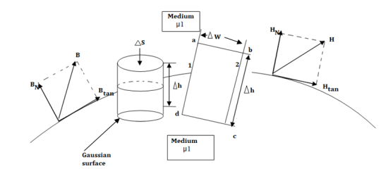
Figure: The boundary between conductor and free space.
Consider a boundary between conductor and free space. The conductor has infinite conductivity. For ideal conductor
The field intensity inside the conductor is zero and flux density inside a conductor is zero.
No charge can exist within a conductor. The charge appears on the surface in the form of surface charge density.
The charge density within the conductor is zero.
Thus  and
and  within the conductor is zero.
  is the surface charge density.
In order to determine the boundary conditions, use the closed path and Gaussian surface.
 at the boundary.
Let  be the electric field intensity in the direction making some angle with the boundary. This
  is resolved into two components
The component tangential to the surface
The component normal to the surface.

The integral of  carried over a closed contour is zero that is the work done in carrying unit positive charge along the closed path is zero.
Consider a rectangular closed path abcda as shown in figure. It is traced in clockwise direction hence

Is divided into four parts:

The closed contour is placed in such a way that its two sides a-b and c-d are parallel to tangential direction to the surface while the other two are normal to the surface at the boundary.
The rectangle with height  and width
  is placed in a manner that half of it is conductor and remaining half is free space. Thus
  is in the conductor and
  in free space.
The portion of c-d in conductor where  hence the corresponding integral is zero.

The width  therefore E is constant hence,

But  is tangential to the boundary hence
 where
where 
Ow b-c is parallel to the normal component therefore  along this direction. Let

For small height  EN is assumed constant and taken out of integration.

But out of b-c, b-2 is in free space and 2-c is in the conductor when 


For path d-a the condition is same as for b-c only direction is opposite.

Substituting eq 4 and 8 and 3 and 9 we get


Thus, the tangential component of the electric field intensity is zero at the boundary between conductor and free space.
DN at the boundary
To find the normal component of  select a closed Gaussian surface in the form of right circular cylinder as shown in figure.
  is placed in such a way that
  is in the conductor and
  is in free space. Its axis is normal direction to the surface.
According to Gauss’s law ,

The surface integral must be evaluated over three surfaces top , bottom and lateral.
Let the area of top and bottom be same S

The bottom surface is in conductor where  hence corresponding integral is zero.
The top surface is in free space hence top surface is shifted at the boundary with 

The lateral surface area is 2π r  where r is the radius of the cylinder. But as
  ->0 this area reduces to zero and the integral is zero.
While only component  is normal having magnitude DN the top surface is very small over which DN can be assumed constant and taken out of integration.


From Gauss’s Law

But at the boundary the charge exists in the form of surface charge density  s
s

Equating 16 and 17 we get


Thus the flux leaves the surface normally and the normal component of flux density is equal to surface charge density


Boundary conditions between conductor and dielectric
The free space is dielectric with Thus if the boundary is between conductor and dielectric with


Problem:
A potential field is given as V = 100 e -5x sin 3y cos 4z V. Let point P (0.1, ,
,  ) be located at a conductor free space boundary. At point P find the magnitudes of
a) V b)  c) Et d) EN e)
  f) DN g)
At P , x=0.1 , y=  z =
z =  / 24.
/ 24.
V = 100 e – 0.5 sin 3 / 12 cos 4
 / 24 = 37.1422 V

= -100[-5 e 5x sin 3y cos 4z e -5x (3) (cos3y)(cos 4z)
 + e-5x (sin 3y) (4) (-sin 4z)
At P
 = [-100[-1.857
  = 1.114
  + 85.776
  ]= 185.7
  -111.4
  + 85.776
|E| = 232.9206 V/m
c ) Et = 0 V/m P is on the boundary.
d ) EN = | | = 232.9206 V
e )  = 8.854 x 10 -12 [185.7
  -111.4
  + 85.776
  ]
]
 = 1.992 nC /m2
DN = = 1.992 nC /m2
 = 1.992 nC / m2
From the Gauss’s law in the point form Poisson’s equation can be derived. Consider the Gauss’s law in the point form as

Where  Flux density and
  Volume charge density
It is known that for a homogeneous, isotropic, and linear medium, flux density and electric field intensity are directly proportional. Thus,
 (1)
(1)
 (2)
(2)
 (3)
(3)
From the gradient relationship,
 (4)
(4)
Substituting (4) in (3)
 (5)
(5)
Taking - outside as constant,


Now  operation is called ‘del squared’ operation and denoted as

The above equation is called Poisson’s equation.
If in a certain region volume change density is zero which is true for dielectric medium then the Poisson’s equation takes the form
 (For charge free region)
This is special case of Poisson’s equation is called Laplace’s equation. The  operation is called the Laplacian of V
Applications of Poisson’s and Laplace’s equations
Laplace's equation is of primary importance in solving electrostatic problems involving a set of conductors maintained at different potentials. Examples of such problems include capacitors and vacuum tube diodes. Laplace's and Poisson's equations are not only useful in solving electrostatic field problem; they are used in various other field problems. For example, V would be interpreted as magnetic potential in magnetostatics, as temperature in heat conduction, as stress function in fluid flow, and as pressure head in seepage.
Boundary-value problems are those in which the potentials or their derivatives at the boundaries of a region are specified and we are to determine the potential field within the region. They are solved by using Poisson's equation if 
 or Laplace's equation if
  = 0.
= 0.
It is a very powerful technique for solving electrostatics problems involving charges and conductors.
When a charge distribution is placed over an infinite ground plane Coulomb’s law and Gauss’s law cannot be readily applied.
Solving Poisson’s or Laplace’s equation is an option, but this is also mathematically challenging, likely to require a numerical solution
It turns out that an electrically equivalent problem can be created using the image distribution with the ground plane removed.
A simple example of a single point charge Q distanced above a ground plane is shown in Figure.

Figure: Electric field lines
Consider a point charge q held as a distance d above an infinite grounded conducting plane as shown in Figure The electrostatic potential of this system must satisfy the following two boundary conditions:
V(x,y,z) =0
 A direct calculation of the electrostatic potential cannot be carried out since the charge distribution on the grounded conductor is unknown.
Note: the charge distribution on the surface of a grounded conductor does not need to be zero.
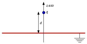
Figure: Method of images
Consider a second system, consisting of two point charges with charges +q and -q, located at z = d and z = -d, respectively as shown in figure. The electrostatic potential generated by these two charges can be calculated directly at any point in space. At a point P = (x, y, 0) on the xy plane the electrostatic potential is equal to

Since this solution satisfies the boundary conditions, it must be the correct solution in the region z > 0 for the system shown in Figure. This technique of using image charges to obtain the electrostatic potential in some region of space is called the method of images.
The electrostatic potential can be used to calculate the charge distribution on the grounded conductor. Since the electric field inside the conductor is equal to zero, the boundary condition for  shows that the electric field right outside the conductor is equal to
Where σ is the surface charge density and  is the unit vector normal to the surface of the conductor. Expressing the electric field in terms of the electrostatic potential V we can rewrite this equation as
 Substituting the solution for V in this equation we find


Only in the last step of this calculation have we substituted z = 0. The induced charge distribution is negative and the charge density is greatest at (x = 0, y = 0, z = 0). The total charge on the conductor can be calculated by surface integrating of σ:

Where . Substituting the expression for σ in the integral we obtain

As a result of the induced surface charge on the conductor, the point charge q will be attracted towards the conductor. Since the electrostatic potential generated by the charge image-charge system is the same as the charge-conductor system in the region where z > 0, the associated electric field (and consequently the force on point charge q) will also be the same. The force exerted on point charge q can be obtained immediately by calculating the force exerted on the point charge by the image charge. This force is equal to

There is however one important difference between the image-charge system and the real system. This difference is the total electrostatic energy of the system. The electric field in the image-charge system is present everywhere, and the magnitude of the electric field at (x, y, z) will be the same as the magnitude of the electric field at (x, y, -z).
On the other hand, in the real system the electric field will only be non-zero in the region with z > 0. Since the electrostatic energy of a system is proportional to the volume integral of  the electrostatic energy of the real system will be 1/2 of the electrostatic energy of the image-charge system (only 1/2 of the total volume has a non-zero electric field in the real system). The electrostatic energy of the image-charge system is equal to

The electrostatic energy of the real system is therefore equal to
Wreal =  Wimage =
The electrostatic energy of the real system can also be obtained by calculating the work required to be done to assemble the system. In order to move the charge q to its final position we will have to exert a force opposite to the force exerted on it by the grounded conductor. The work done to move the charge from infinity along the z axis to z = d is equal to

Which is identical to the result obtained using the electrostatic potential energy of the image-charge system.
Key Takeaways
- It is a very powerful technique for solving electrostatics problems involving charges and conductors.
- It turns out that an electrically equivalent problem can be created using the image distribution with the ground plane removed.
- This technique of using image charges to obtain the electrostatic potential in some region of space is called the method of images.
The electrostatic energy of the image-charge system is equal to

- The electrostatic energy of the real system is therefore equal to Wreal =
 Wimage =
References:
1. WH Hayt and JA Buck, “Engineering Electromagnetic”, McGraw- Hill Education.
2. Antenna and wave propagation by k.d parsad satya prakashan.