Unit – 3
Magneto Statics
Up until now, we have been discussing electrostatics, which deals with physics of the electric field created by static charges. We will now investigate a different phenomenon, that of production and properties of magnetic field, whose source is steady current, i.e., of charges in motion.
An essential difference between the electrostatics and magnetostatics is that electric charges can be isolated, i.e., there exist positive and negative charges which can exist by themselves. Unlike this situation, magnetic charges (which are known as magnetic monopoles) cannot exist in isolation, every north magnetic pole is always associated with a south pole, so that the net magnetic charge is always zero. We emphasize that there is no physical reason as to why this must be so. Nevertheless, despite best attempt to isolate them, magnetic monopoles have not been found. This, as we will see, brings some asymmetry to the physical laws with respect to electricity and magnetism.
Sources of magnetic field are steady currents. In such a field a moving charge experiences a sidewise force. Recall that an electric field exerts a force on a charge, irrespective of whether the charge is moving or static. Magnetic, field, on the other hand, exerts a force only on charges that are moving. Under the combined action of electric and magnetic fields, a charge experiences, what is known as Lorentz force.
It is the force exerted on the charged particle q moving with velocity v through an electric field E and magnetic field B. The entire electromagnetic force F on the charged particle is called Lorentz force which is given by
F = qE + qv x B ---------------------(1)
The first term indicates electric field. The second term indicates magnetic force which has direction perpendicular to both velocity and magnetic field.
The magnetic force is proportional to q and to the magnitude of the vector cross product v × B. In terms of the angle ϕ between v and B, the magnitude of the force equals qvB sin ϕ.
If v is perpendicular to B the particle will follow circular trajectory with radius of r = mv/qB. If the angle ϕ is less than 90°, the particle orbit will be a helix with an axis parallel to the field lines.
If ϕ is zero, there will be no magnetic force on the particle, which will continue to move undeflected along the field lines.
When a conductor is placed with B field perpendicular to current, the magnetic force on both types of charge carriers is in the same direction. This force gives rise to small potential difference between the sides of the conductor.
If a wire with a current i is placed in an external magnetic field B, Since, current represents movement of charges in the wire, the Lorentz force acts on the moving charges. Because these charges are bound to the conductor, the magnetic forces on the moving charges are transferred to the wire.
The force on a small length dl of the wire depends on the orientation of the wire with respect to the field. The magnitude of the force is given by I dlB sin ϕ, where ϕ is the angle between B and dl. There is no force when ϕ = 0 or 180°, both of which correspond to a current along a direction parallel to the field. The force is at a maximum when the current and field are perpendicular to each other. The force is given by dF= idl × B.
Magnetic field intensity (H)
The Magnetic Field Intensity or Magnetic Field Strength is a ratio of the MMF needed to create a certain Flux Density (B) within a material per unit length of that material.
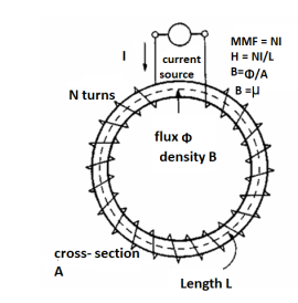
H = At/m, ampere-turns per meter. N is used as the number of turns of wire around a core or magnetic material. So, H = N*I/m.
This is the horizontal axis of the B-H curve for magnetic materials, and is used to vary the magnetic flux within the material by varying the current in the solenoid, thus varying the at (varying the amperes of the ampere-turns).
To determine the B-H curve of a material, the H is varied by controlling the magnitude and polarity of the current flowing in the coil around the sample material, and B is measured.
Let us consider a conductor carrying direct current I and a steady magnetic field is produced around it. The law helps us to obtain magnetic field intensity  produced at a point P due to differential current element idL. The current carrying conductor is as shown in the figure.
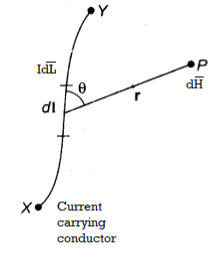
Consider differential length dL and differential current IdL. This is a small part of the current carrying conductor. The point P is at a distance R from differential current element.  is the angle between the differential current element and the line joining point P to the differential current element?
Bio-Savart Law states that the magnetic field intensity  produced at point P due to differential current IdL is,
Proportional to the product of current I and differential length dL.
The sine of angle between the element and the line joining point P to the element.
Inversely proportional to the square of distance R between point P and the element.
Bio-Savart law can be stated as,
d α I dL sin Ɵ / R 2
d =k I dL sin Ɵ / R 2
Where k = constant of proportionality
In SI units, k = 1/ 4 π.
d = I dL sin Ɵ / 4πR 2
In vector form,
Let dL = Magnitude of vector length  and
and
 R = Unit vector in the direction from differential current element to point P.
Then from rule of cross product,
 |
|

Replacing we get
d = I d
= I d  x
x  R / 4πR 2 A/m
 R =
R =  / |
/ | =
=  / R
/ R
d = I d
= I d  x
x  / 4πR 3 A/m
This is the mathematical form of Bio-Savarts Law.
According to direction of cross product the direction of  is normal to the plane containing two vectors and the normal direction along the progress of right- handed screw turned from
  through smaller angle
  towards the line joining element to point P.
Therefore, direction of  is normal to the plane of paper.
According to right- handed screw rule the direction of  is going into the plane of paper.
The entire conductor is made of differential elements. Therefore, in order to obtain the total magnetic field take the integral
 =
=  d
d  x
x  R / 4πR 2
The closed line integral is required to ensure that all the current elements are considered because current can flow only in the closed path provided by close circuit.
If the current element is considered at point 1 and point P at point 2 as shown in the figure, then
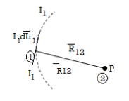
D  2 = I1 d
  1 x x
1 x x  R 12 / 4πR 2 12
Where
I1 = current flowing through dL1 at point 1.
DL1 = Differential vector length at point 1
 R12 = Unit vector in the direction from element at point 1 to point P at point2.
 R12 =
R12 =  / |
/ | | =
| =  / R12
/ R12
 =
=  d
d  x
x  R12 / 4 π R 2 12 A/m
This integral form is called Biot-Savart law.
Problem:
Find the incremental field strength at P2 due to the current element of 2πa2 Am at P1. The co-ordinates of P1 and P2 are (4,0,0) and (0,3,0) respectively.
Solution:
The two points P1 and P2 along with the I1dL1 current element at I1 are shown in figure.
According to Bio-Savart law
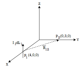
d  = I1 d
  x
x  R12 / 4 π R 2 12
 = (0-4)
  + (3-0) ay + 0. Az
 R12 =
R12 =  12 /|
12 /|  12 |
12 |
= -4  x + 3
x + 3  y /
y /  16 + 9
= -4  x + 3
x + 3  y /5
y /5
While I1 dL1 = 2
 A m.
A m.


Gauss’s Law is useful to obtain  in case of complex problems. I magnetostatics complex problems can be solved using Ampere’s Law.
It states that
The line integral of magnetic field intensity  around closed path is exactly equal to direct current enclosed by that path.
The mathematical representation of Ampere’s circuital law is
 ---------------------(1)
This law is useful to determine  when current distribution is symmetrical.
Proof:
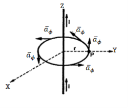
Consider a long straight conductor carrying direct current I placed along z axis as shown in figure. Consider a closed circular path of radius r which encloses the straight conductor carrying direct current I. The point P is at perpendicular distance r from the conductor.
Consider  at point P which is direction
  direction tangential to circular path at point P.
Therefore,
 (2)
(2)
While  obtained at point P, from Biot-Savart law due to infinitely long conductor is,

= 1/ 2  r . dɸ = 1/ 2 π . dɸ
Integrating  over the entire closed path

This proves that the integral  along closed path gives the direct current enclosed by that closed path.
Steps to Apply Amper’s Circuital Law:
Step1: Consider a closed path preferably symmetrical such that it encloses the direct current I once. This is Amperian path.
Step2: Consider differential length  depending upon the co-ordinate system used.
Step3: Identify the symmetry and find in which direction  exists according to co-ordinate system used.
Step 4: Find  . Make sure that
  and
and  are in the same direction.
Step 5: Find the integral of  around the closed path. And equate it to current I enclosed by the path.
To apply Ampere’s circuital law the following conditions must be satisfied,
- The
 ie either tangential or normal to the path, at each point of the closed path.
 - The magnitude of
 must be same at all points of the path where
  is tangential.
 due to straight conductors.
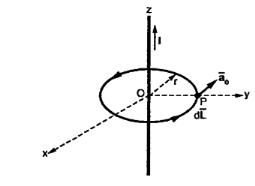
Consider an infinitely long straight conductor which is placed along z-axis carrying direct current I as shown in figure. Consider the Amperian closed path enclosing the conductor as shown in figure. Consider point P on the closed path at which  is obtained. The radius of the path is r from the conductor. The magnitude of
  depends on r and the direction is always tangential to the closed path. So,
  has only component in
 direction say H
  .
.
Consider elementary length  at point P in cylindrical co-ordinates it is r d
 in
in  .
.
 = Hɸ
= Hɸ  and
and  = r dɸ .
 .
.  = Hɸ
= Hɸ  . r dɸ .
 = Hɸ r dɸ
According to Ampere’s circuit law,
 = I
= I
 ɸ . r. dɸ = I
Hɸ . r  . dɸ = I
Hɸ . r [2π] =I
Hɸ = 1/ 2π r
Hence  at point P is given by
 = Hɸ.
= Hɸ.  = 1/ 2 π r .
Ampere's circuit law states that the line integral of H around a closed path is the same as the net current Ienc enclosed by the path.
In other words, it can be said that the circulation of H equals Ienc:
 …. (1)
Ampere's law is similar to Gauss's law, since Ampere's law is easily applied to determine H when the current distribution is symmetrical.
Ampere’s law is a special case of Biot-Savart’s Law, it can be derived from Biot-Savart’s Law.
By applying Stokes's theorem to the left-hand side of equation 1, we get:

But

If we compare the two surface integrals, then:
 …….(2)
This is the third Maxwell Equation; it is essentially Ampere's law in differential
Form, whereas eq. 1 is the integral form.
Also, in Eq. 2  ; that is a magnetostatic field is not conservative.
For time varying Magnetic Fields, (2) is written as:

The term  is known as displacement current density.
Magnetic Flux Density
The magnetic flux density B is similar to the electric flux density D. As D =  in free space, the magnetic flux density B is related to the magnetic field intensity H as:
B = ……..(1)
Where  is a constant known as the permeability of free space. The constant is in henrys per meter (H/m) and has the value of

The magnetic Flux through a surface S is given by:
 …….(2)
Where the magnetic flux  ' is in webers (Wb) and the magnetic flux density is in webers per square meter (Wb/m2) or Tesla’s (T).
Unlike electric flux lines, magnetic flux lines always close upon themselves. This is because it is not possible to have isolated magnetic poles (or magnetic charges).
 ……….(3)
This equation is referred to as the law of conservation of magnetic flux or Gauss's law for magnetostatic fields. Although the magnetostatic field is not conservative, magnetic flux is conserved.
By applying Divergence Theorem to equation 3, we obtain:
 ………..(4)
This equation is the fourth Maxwell's equation. It also shows that magnetostatic fields have no sources or sinks. It means that magnetic field lines are always continuous.
Problem:
The following four vector fields are given in Cartesian co-ordinate system. The vector field, which does not satisfy the property of magnetic flux density, is
(a) 

(c) 

Solution
As we know that divergence of magnetic field is zero, therefore B=0
For  the above relation becomes


From the given options, option(c) does not satisfy the above relation.
Hence the correct option is (c)
To apply Ampere’s circuital law the following conditions must be satisfied,
- The
 ie either tangential or normal to the path, at each point of the closed path.
 - The magnitude of
 must be same at all points of the path where
  is tangential.
 due to straight conductors.
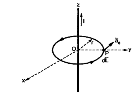
Consider an infinitely long straight conductor which is placed along z-axis carrying direct current I as shown in figure. Consider the Amperian closed path enclosing the conductor as shown in figure. Consider point P on the closed path at which  is obtained. The radius of the path is r from the conductor. The magnitude of
  depends on r and the direction is always tangential to the closed path. So,
  has only component in
  direction say H
  .
.
Consider elementary length  at point P in cylindrical co-ordinates it is r d
 in
in 
 and
and 

According to Ampere’s circuital law


Hence  at point P is given by

Circular loop:
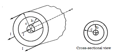
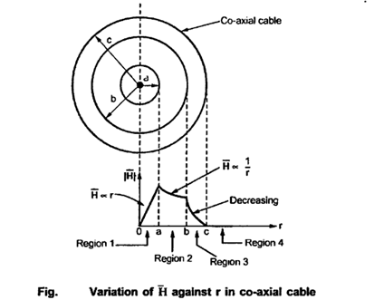
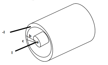
Consider a co-axial cable where the inner conductor is solid with radius a , carrying direct current I. The outer conductor is in the form of concentric cylinder whose inner radius is b and outer radius is c. The cable is placed along z-axis. The current I is uniformly distributed in the inner conductor. When -I is uniformly distributed in the outer conductor.
The space between inner and outer conductor is filled with dielectric say air. The calculation of  is divided corresponding to various regions of the cable.
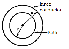
Region1: Within the inner conductor r<a . Consider a closed path having radius r<a. Hence it encloses only part of the conductor as shown in figure.
The area of cross-section is enclosed in  r2 m2 . The total current flowing is I through area
  a 2 . Hence the current enclosed by the losed path is.
 (1)
(1)
The  is again only in
  direction and depends only on r.

So consider  in the
  direction which is rd


According to Ampere’s circuital law,


r<a within conductor
Region 2:
Within a<r<b consider a circular path which encloses the inner conductor carrying direct current I. This is the case of infintely long conductor along z-axis. Hence,  in this region is

Region 3:
Within the outer conductor b<r<c
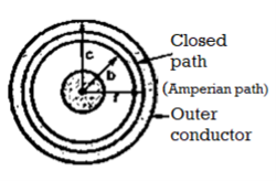
Consider the closed path as shown in figure. The current enclosed is the only part of the curent -I, in the outer conductor. The total current _I is flowing through the cross section  ( c2 – b2) while the closed path encloses the cross section
  ( r2 – b2). Hence, the current enclosed by the closed path of the outer conductor is

 Current in inner conductor enclosed
Total current enclosed by the closed path is


Accordign to ampere’s circuital law

Now  is again in
  direction only and is a function of r only.
 and
and 
 rd
rd


Region4:
Outside the cable r>c
Consider the closed path with r>c such that it encloses both the conductors that is both currents +I and _I.
The total current enclosed is,
I enc = +I -I = 0A

 r>c
r>c
The magnetic field does not exist outside the cable. The variation of  R is
R is
Infinite sheet of current
Consider an infinite sheet of current in the z=0 plane. The surface current density is  . The current is flowing in positive y direction hence
  Ky
Ky  y. This is shown in figure.
Consider a closed path 1-2-3-4 shown in figure. The width of the path is b while the height is a. It is perpendicular to the direction of current in xz plane.
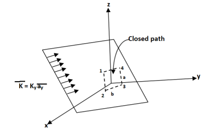
The current flowing across the distance b is given by Kyb

Consider the magnetic lines of force due to current in  direction according to right thumb rule. These are shown in figure.
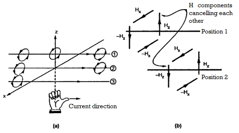
In Figure b it is clear that in between two very closed spaced conductors the components of  in z direction are oppositely directed. All such components cancel each other and hence
  cannot have any component in z direction.
As current is flowing in y direction  cannot have component in y direction.
So  has only component in x direction
 .. For z>0 (7(a))
 for z<0 (7(b))
Applying Ampere’s circuit law,
 (8)
(8)
For path 1-2

For path 3-4

But  is in x direction while
Hence along the paths 1-2 and 3-4 the integral 
Consider path 2-3 along which


The path 2-3 is lying in z<0 region for which  is -Hx
  . And the limits from 2 to 3 positive x to negative x hence effective sign of the integral is positive.
Consider the path 4-1 along which  and it is in the region z>0 hence.


Equating this to  in equation (6)


Hence  for z>0
 for z<0
In general for an infinite sheet of current density  we can write

Where  Unit vector normal from the current sheet to the point at which
  is to be obtained.
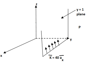
Q. The plane y=1 carries current density  . Find H at A(0,0,0) and B(1,5,-2).
Solution:
The sheet is located at y=1 on which K is in  direction. The sheet is infinite and shown in figure.
The  will be in x direction.
a) Pint A(0,0,0)

Normal to current sheet at point A.

Now 


b) Point B(1,5,-2)
This is to the right of the plane as y=5 for B.
 normal to sheet at point B


Problem:
In the region 0<r<0.5m in cylindrical co-ordinates the current density is  and J=0 else where. Use Amperes circuital law to find
The current from current density is given by

 normal to
  as
as  is in
is in 

Using integration by parts

=4.5(2π)


For r=0.5, I=7.608[1-0.3678-0.3678]=1.8676 A
Consider a closed path with r ≥ 0.5 such that the enclosed current I is 1.876 A. According to Ampere’ circuital law,


 for r
for r
Q. A ‘z’ directed current distribution is given by
 . Find
  at any point using Amper’s circuital law.
Sol:
As current density is given by


Consider a closed path with  which is Amperian path.
 while
while 
According to ampere’s circuital law
 as path has r
 a, it encloses total I.


Assuming permeability of medium as

In free space
In free space, magnetic flux density B is defined as:
 Webers/m2 or Tesla (T).
 (henry/meters)
μ is the permeability of free space.
The total magnetic flux through a surface is given by

Applying the definition of the divergence,

Therefore, the lines H or B are closed lines (E or D are open lines).
Conductor
For the magnetic flux between the conductors of a coaxial line of length d, the magnetic flux density is given by

The magnetic flux contained between the conductors in a length d is the flux crossing any radial plane extending from  = a and
  = b and from z=0 and z=d.


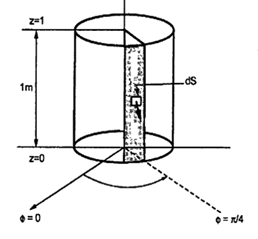
Problem: A radial field  = 2.39 x 10 6 / r cos
  A/m exists in free space. Find the magnetic flux crossing the surface defined by 0 ≤
 ≤ π/4 and 0 ≤ z ≤ 1m.
Solution:
The portion of the cylinder is shown in figure. The flux crossing the given surface is given by

 normal to
  direction is,


Problem: Find the flux passing the portion of the plane  = π / 4 defined by 0.01 < r < 0.05m and 0<z<2 m. A current filament of 2.5 A is along z-axis in the
  direction in free surface.
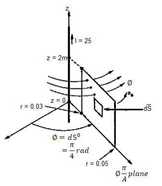
Due to current carrying conductor in free space along z-axis

 A/m
A/m


The flux crossing the surface is given by


 normal to
  direction


According to Ampere’s circuit law the line integral of magnetic field around a closed path is equal to the current enclosed by the path.
 .
.  = I enclosed ---------------------------------------------------------(1)
Replacing current by the surface integral of conduction current density  over an area bounded by the path of integration of
  we get
 .
.  =
=  .dS ---------------------------------------------------------------(2)
Above expression can be made further general by adding displacement current density to conduction current density as follows
 .
.  =
=  +
+  /
/  t . d
t . d -------------------------------------------------(3)
Eq(3) is called the Maxwell equation.
Key Takeaways:
Maxwell's equations are partial differential equations. They link the spatial and temporal rates of change of electric and magnetic fields, and they show how these rates of change are related to the sources of the fields.
If Vm is the scalar magnetic potential, then it must satisfy the equation

But the scalar magnetic potential is related to the magnetic field intensity  as
as
 = -
= -  Vm
Vm
 x (-
x (-  =0 that is
  x (
x (  =0
=0
 x (
x (  =
=  that is
  =0
=0
Thus scalar magnetic potential Vm can be defined for source free region where  that is the current density is zero.
 = -
= -  Vm only for
  =0
=0
Vector magnetic potential:
The vector magnetic potential is denoted as  and measured in Wb/m . It has to satisfy equation that divergence of a curl of a vector is always zero.
 .
. 
 .
.  =0
=0
 =
= 

The curl of a vector magnetic potential is the flux density.
Now  .
.  =
= 

 /
/  =
= 
 =
= 


 =
= 

 x
x  x A = =

Using vector identity to express on L.H.S we write

 = =
= =  J
J
J = 1/  [
[ 
 ] = 1/ 1/
  [
[  x
x  ) -
) -  2
2  ]
]
Thus if vector magnetic potential is known then current density J can be obtained.
Solved Examples
Q1. The plane of a circular coil is horizontal. It has 10 turns each of 8 cm radius. A current of 2 A flows through it, which appears clock wise from a point vertically above it. Find the magnitude and direction of the magnetic field at the centre of the coil due to current.
Sol. Here, n=10, I=2A
r= 8cm = 0.08 m
Magnitude of magnetic field induction at the centre of the circular coil carrying current is


Q2. A long straight solid metal road of radius 4 cm carries a current 2A uniformly distributed over its circular cross section. Find the magnetic field induction of a distance 3 cm from the axis of wire.
Sol. The point P is lying inside the rod at perpendicular distance (r=3cm) from the axis of wire. Draw a circular closed path of radius r with centre on axis of rod such that the point P lies on this closed path.
Current enclosed by closed path

The magnetic field produced due to current flowing in the rod at every pointover the closed path is tangential to it and is equal in magnitude at all points of path.
Line integral of  over closed path is


Or,


Q3. Determine the magnetic flux density B distance d meter from infinite straight wire carrying current I.
Sol. Let P be the point where B is to be evaluated consider an element it yr=dl of infinite wire shown in figure 1 tattoo distance r from point P.
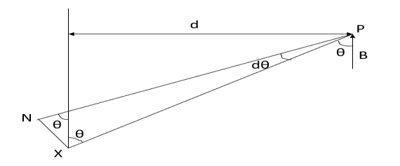
Figure: An infinite wire carrying a current I
Magnetic field B at P due to element dl from equation is given by

We see that
 d
d
Therefore, 


Substituting their values in above expression we have


Q4. Compute curl A if .
.
Sol. Given that


Partial derivatives will be


Putting these values of partial derivations in in equation


Q5. Verify that the vector field is both irrational (π has zero curl) and
Solenoid (π has zero divergence)
Sol. (i) given that

The partial derivatives will be


Putting these values of partial derivatives in curl equation


Hence the given field A is irrational since its curl zero
(ii) substituting the above calculated value of partial derivatives


Hence the given field is solenoid since divergence is zero.
Q5. Find the work done by the force vector  .
.
Around the closed path as shown in figure.
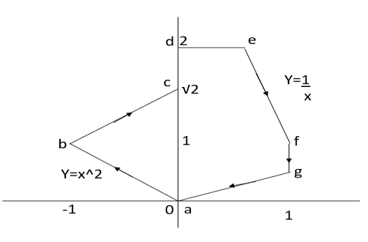
Sol. The total work done by the force vector is

The integrals consists of 7 parts which can be calculated separately


This problem can be solved by Stokes theorem.
According two stokes theorem, the work done by force vector is
 where S is surface bounded by the closed path and F is the given force vector for this force vector the curl is equal to
Choose normal vector


Q6. Find the curl of magnetic field and show that it is proportional to the current density.
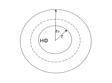
Figure. Cross section of cylindrical conductor
Sol. For the cylindrical coordinates

But is entirely in the Q directions

The variation of is along r axis


Which is proportional to J.
Q7. Calculate the magnetic flux density due to coil 100 ampere turn and area of  on the axis of coil at a distance 10 metre from the centre and at a point distance 10 metres in a direction at right angle to axis.
Sol. B on the axis of the coil


(ii) B ad perpendicular to axis
B at any point ( ) is given by


M- Magnetic moment of a current loop and is equal to 

When


Putting the given values we have


Q8. Circuit carrying a current of I ampere from a regular polygon of n side inscribed in circumscribing circle of radius R. Calculate the magnetic flux density at the centre of the polygon and show that for a circular loop if n tends to infinity.
Sol. Since the given regular polygon has n sides


P is perpendicular chopped from centre to the sides AB and OAB is an equilateral triangle.


B due to AB is given by


 due to regular polygon of n sides will be

When n tends to


 at the centre of the circular loop of radius R.
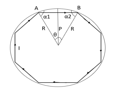
Figure: Regular polygon inscribed in a circle of radius R.
References:
1. WH Hayt and JA Buck, “Engineering Electromagnetic”, McGraw- Hill Education.
2. Antenna and wave propagation by k.d parsad satya prakashan.