Unit - 2
Resonance
Definition: it is defined as the phenomenon which takes place in the series or parallel R-L-C circuit which leads to unity power factor
Voltage and current in R – L - C circuit. Are in phase with each other
Resonance is used in many communicate circuit such as radio receiver.
Resonance in series RLC series resonance in parallel RLC anti resonance / parallel resonance.
- Condition for resonance XL = XC
- Resonant frequency (Fr): for given values of R-L-C the inductive reactance XL become exactly equal to the capacitive reactance Xc only at one particular frequency. This frequency is called as resonant frequency and denoted by (fr)
- Expression for resonant frequency(fr): we know thet XL = 2ƛ FL - Inductive reactance
Xc =  - capacitive reactance
At a particular frequency ȴ = fr, the Inductive and capacitive reactance are exactly equal
 XL = XC ……at ȴ = fr
Ie  L =
L = 
 fr2 =
fr2 = 
 fr =
fr =  H2
H2
And  = wr =
  rad/sec
Series Resonant Circuit
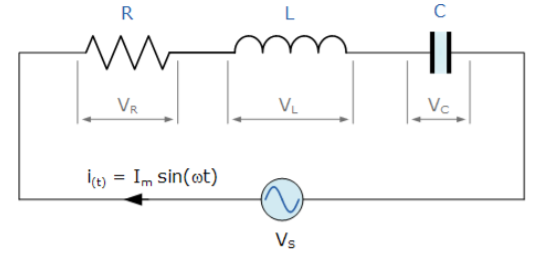
Fig 1 Series RLC Resonant Circuit
Thus far we have seen that the three basic passive components: resistance (R), inductance (L), and capacitance (C) have very different phase relationships to each other when connected to a sinusoidal AC supply. In a pure ohmic resistor the voltage waveforms are “in-phase” with the current. In a pure inductance the voltage waveform “leads” the current by 90o, giving us the expression of: ELI. In a pure capacitance the voltage waveform “lags” the current by 90o, giving us the expression of: ICE. This phase difference, Ф depends upon the reactive value of the components being used and hopefully by now we know that reactance, (X) is zero if the circuit element is resistive, positive if the circuit element is inductive and negative if it is capacitive.
The series RLC circuit above has a single loop with the instantaneous current flowing through the loop being the same for each circuit element. Since the inductive and capacitive reactance’s XL and XC are a function of the supply frequency, the sinusoidal response of a series RLC circuit will therefore vary with frequency, ƒ. Then the individual voltage drops across each circuit element of R, L and C element will be “out-of-phase” with each other as defined by:
i(t) = Imax sin(ωt)
The instantaneous voltage across a pure resistor, VR is “in-phase” with current. The instantaneous voltage across a pure inductor, VL “leads” the current by 90o The instantaneous voltage across a pure capacitor, VC “lags” the current by 90o Therefore, VL and VC are 180o “out-of-phase” and in opposition to each other
The amplitude of the source voltage across all three components in a series RLC circuit is made up of the three individual component voltages, VR, VL and VC with the current common to all three components. The vector diagrams will therefore have the current vector as their reference with the three voltage vectors being plotted with respect to this reference as shown below.
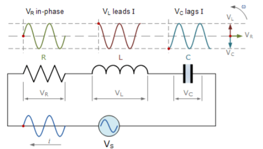
Fig 2 Phasor for series RLC circuit
The value of instantaneous voltages for series RLC circuit is given as
Vs-VR-VL-VC=0
Vs-IR-L -
- =0
=0
Vs = IR+L +
+
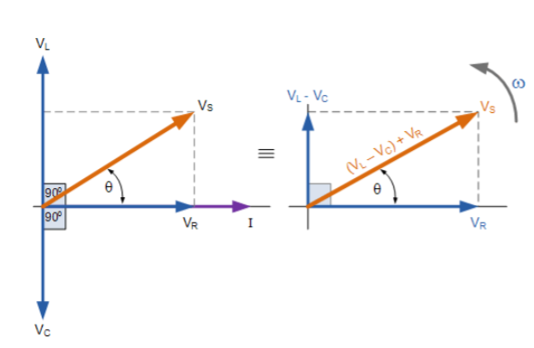
Fig 3 Phasor for Series RLC Circuit
The resulting vector VS is obtained by adding together two of the vectors, VL and VC and then adding this sum to the remaining vector VR. The resulting angle obtained between VS and i will be the circuits phase angle as shown in above figure.
Vs = √
Vs =I Z
Z= √
As the three vector voltages are out-of-phase with each other, XL, XC and R must also be “out-of-phase” with each other with the relationship between R, XL and XC being the vector sum of these three components thereby giving us the circuits overall impedance, Z.
Quality factor / Q factor
The quality of resonance circuit is measured in terms of efficiency of L and C to stare energy and the efficiency of L and C to store energy as measured in terms of a factor called quality factor or Q factor it is expressed as
Q =  and Q =
The sharpness of tuning of R-L-C series circuit or its selectivity is measured by value of Q. As the value of Q increases, sharpness of the curve also increases and the selectivity increases.
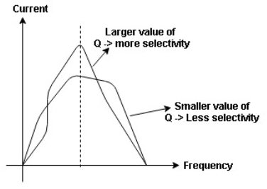
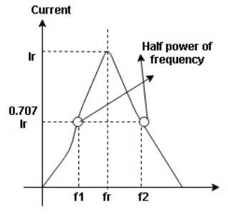
Fig 4 Bandwidth of Resonant Circuit
Bandwidth (BW) = f2 = b1
 and
and  are the frequency at which the power delivered to the resistor is reduced to 50% of the power delivered to it at resonance
  these frequency are called as half power frequency
Bw = fr/Q
As already seen above the bandwidth and quality factor Q are related as
Q=fr/BW
The bandwidth is selected in between -3dB. The ability of circuit to reject any frequency on either side of these points is called as selectivity. The circuit with more selectivity will have narrow bandwidth and the one with less selectivity will have wide bandwidth. When all other parameters are kept constant and only R is varied the value of selectivity can be controlled.
Q= XL/R
Or we can say Q=XC/R
The curve with variation of L and C is shown below. Some specification of series resonant circuit is then defined.
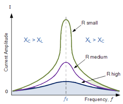
Fig 5 Variation in current
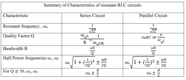
The resonant frequency is derived as
XL= XC
XL- XC=0
ωrL -1/ωrC=0
ωr= 1/√LC
At ωr we see
Imax= Vmax/Z = 
The lower cut-off frequency will now be
Pm/2 at half power
I=Im/√2
Z=√2R
X=-R
The lower cut off frequency is
ωL= 
Similarly, the upper cut-off frequency is
ωH= 
Key takeaway
- The condition for resonance is XL=XC with imaginary part of transfer function as zero.
- The circuit is inductive at high frequencies and has lagging power factor.
- The circuit behaves as capacitive at low frequencies with leading power factor.
- The impedance of the circuit will be Z=R at resonance.
When a coil is in parallel with a capacitor, as shown below. The circuit is said to be in resonance.
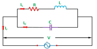
Fig 6 Series RLC circuit
The resonant frequency for above circuit is fr =  Hz
Hz
The current at resonance is I=
The value L/RC is known as dynamic impedance.
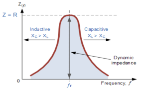
Fig 7 Bandwidth of RLC Circuit
The current at resonance is minimum. The circuits admittance must be at its minimum and one of the characteristics of a parallel resonance circuit is that admittance is very low limiting the circuits current. Unlike the series resonance circuit, the resistor in a parallel resonance circuit has a damping effect on the circuit bandwidth making the circuit less selective.
Also, since the circuit current is constant for any value of impedance, Z, the voltage across a parallel resonance circuit will have the same shape as the total impedance and for a parallel circuit the voltage waveform is generally taken from across the capacitor.
Bandwidth and selectivity:
 and
and  are the frequency at which the power delivered to the resistor is reduced to 50% of the power delivered to it at resonance
  thesefrequency are called as half power frequency
Bw = fr/Q
Q =  =
=  fCR = R
Resonant Frequency:
The resonant frequency for parallel resonant circuit is given as
fR= 
Where L= inductance of the coil
C = is the capacitance
Rs = Resistive value of coil.
Key takeaway
Examples
Que) A coil takes a current of 6A when connected to 24V dc supply. To obtain the same current with 50HZ ac, the voltage required was 30V. Calculate inductance and p.f of coil?
Sol: The coil will offer only resistance to dc voltage and impedance to ac voltage
R =24/6 = 4ohm
Z= 30/6 = 5ohm
XL = 
= 3ohm
Cosφ =  = 4/5 = 0.8 lagging
Que) The potential difference measured across a coil is 4.5V, when it carries a dc current of 8A. The same coil when carries ac current of 8A at 25Hz, the potential difference is 24V. Find current and power when supplied by 50V,50Hz supply?
Sol: R=V/I= 4.5/8 = 0.56ohm
At 25Hz Z= V/I=24/8 =3ohm
XL = 
= 2.93ohm
XL = 2 fL = 2
 x 25x L = 2.93
L=0.0187ohm
At 50Hz
XL = 2x3 =6ohm
Z =  = 5.97ohm
I= 50/5.97 = 8.37A
Power = I2R = 39.28W
Que) A coil having inductance of 50mH an resistance 10ohmis connected in series with a 25 F capacitor across a 200V ac supply. Calculate resonant frequency and current flowing at resonance?
Sol: f0= = 142.3Hz
I0 = V/R = 200/10 = 20A
Que) A 15mH inductor is in series with a parallel combination of 80ohm resistor and 20 F capacitor. If the angular frequency of the applied voltage is 1000rad/s find admittance?
Sol: XL = 2 fL = 1000x15x10-3 = 15ohm
XL = 1/ C = 50ohm
Impedance of parallel combination Z = 80||-j50 = 22.5-j36
Total impedance = j15+22.5-j36 = 22.5-j21
Admittance Y= 1/Z = 0.023-j0.022 siemens
Que) A circuit connected to a 100V, 50 Hz supply takes 0.8A at a p.f of 0.3 lagging. Calculate the resistance and inductance of the circuit when connected in series and parallel?
Sol: For series Z =100/0.8 = 125ohm
Cosφ = 
R = 0.3 x 125 = 37.5ohm
XL =  = 119.2ohm
XL = 2 fL = 2
 x 50x L
119.2 = 2 x 50x L
L= 0.38H
For parallel:
Active component of current = 0.8 cosφ = 0.3x0.3 = 0.24A
R = 100/0.24 =416.7ohm
Quadrature component of current = 0.8 sinφ = 0.763
XL= 100/0.763 = 131.06ohm
L= 100/0.763x2 x50 = 0.417H
Que) For a series RLC circuit having R=10ohms, L= 0.15H, C=100 F. They are connected across 100v 50Hz supply. Calculate total impedance?
Sol: Impedance Z= 
Z=  = 18.27ohm
Que) For a series RLC circuit having R=12ohms, L= 0.2H, C=60 F. They are connected across 100v 50Hz supply. Calculate circuit current?
Sol: I= 
Z= 
Z=  = 13.89ohm
I = 100/13.89 =7.2A
Que) For a series RLC circuit having R=10ohms, L= 0.15H, C=100 F. They are connected across 100v 50Hz supply. Calculate power factor?
Sol: cosφ = 
Impedance Z= 
Z=  = 18.27ohm
Cosφ =  =
= 
φ = 56.81o lagging
The circuits we have considered so far may be regarded as conductively coupled, because one loop affects the neighboring loop through current conduction. When two loops with or without contacts between them affect each other through the magnetic field generated by one of them, they are said to be magnetically coupled. The transformer is an electrical device designed on the basis of the concept of magnetic coupling. It uses magnetically coupled coils to transfer energy from one circuit to another.
Transformers are key circuit elements. They are used in power systems for stepping up or stepping down ac voltages or currents. They are used in electronic circuits such as radio and television receivers for such purposes as impedance matching, isolating one part of a circuit from another, and again for stepping up or down ac voltages and currents. We will begin with the concept of mutual inductance and introduce the dot convention used for determining the voltage polarities of inductively coupled components.
Based on the notion of mutual inductance, we then introduce the circuit element known as the transformer. We will consider the linear transformer, the ideal transformer, the ideal autotransformer, and the three-phase transformer. Finally, among their important applications, we look at transformers as isolating and matching devices and their use in power distribution.
Mutual Inductance
When two inductors (or coils) are in a close proximity to each other, the magnetic flux caused by current in one coil links with the other coil, thereby inducing voltage in the latter. This phenomenon is known as mutual inductance.
Let us first consider a single inductor, a coil with N turns. When current i flows through the coil, a magnetic flux φ is produced around it (Figure below). According to Faraday’s law, the voltage v induced in the coil is proportional to the number of turns N and the time rate of change of the magnetic flux φ; that is,
V=N 
But the flux φ is produced by current i so that any change in φ is caused by a change in the current.
V= N 

V=L
The inductance L of the inductor is thus given by
L= N 
This inductance is commonly called self-inductance, because it relates the voltage induced in a coil by a time-varying current in the same coil. Now consider two coils with self-inductances L1 and L2 that are in close proximity with each other. Coil 1 has N1 turns, while coil 2 has N2 turns. For the sake of simplicity, assume that the second inductor carries no current. The magnetic flux φ1 emanating from coil 1 has two components: one component φ11 links only coil 1, and another component φ12 links both coils. Hence,
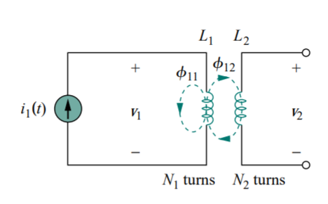
Fig 8 Mutual inductance M21 of coil 2 with respect to coil 1.
φ1 = φ11 + φ12
Although the two coils are physically separated, they are said to be magnetically coupled. Since the entire flux φ1 links coil 1, the voltage induced in coil 1 is
v1 = N1 
Only flux φ12 links coil 2, so the voltage induced in coil 2 is
V2 = N2 
Again, as the fluxes are caused by the current i1 flowing in coil 1,
V2 = N2 
 = M21
= M21 
M21 = N2 
M21 is known as the mutual inductance of coil 2 with respect to coil 1. Subscript 21 indicates that the inductance M21 relates the voltage induced in coil 2 to the current in coil 1. Thus, the open-circuit mutual voltage (or induced voltage) across coil 2 is
V2 = M21 
Suppose we now let current i2 flow in coil 2, while coil 1 carries no current. The magnetic flux φ2 emanating from coil 2 comprises flux φ22 that links only coil 2 and flux φ21 that links both coils. Hence, φ2 = φ21 + φ22
The entire flux φ2 links coil 2, so the voltage induced in coil 2 is
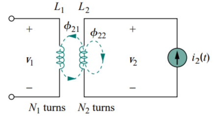
Fig 9 Mutual inductance M12 of coil 1 with respect to coil 2
V2 = N2 
V2 = N2 
 = M12
= M12 
M12 = N1 
Which is the mutual inductance of coil 1 with respect to coil 2. Thus, the open-circuit mutual voltage across coil 1 is
V1 = M12 
Key takeaway
Mutual inductance is the ability of one inductor to induce a voltage across a neighbouring inductor, measured in henrys (H).
- MUTUAL INDUCTANCE: -
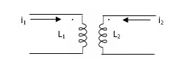
Fig 10 Mutual Inductance
M12= mutual inductance on 1 due to 2
M21= mutual inductance on 2 due to 1
- If current is entering at dot L1then it will produce mutual induction or it will produce a voltage with positive polarity on L2.
- If current is leaving at dot L1then it will produce a voltage with negative polarity on L2.
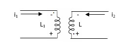
Fig 11 Current entering both dots
Voltage on 2 due to 1 = 
Voltage on 1 due to 2 = 
- When current is entering or leaving from both dots.
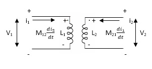
Fig 12 Current entering both dots
 ⎼⎼⎼⎼⎼⎼ 1
 ⎼⎼⎼⎼⎼⎼2
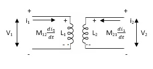
 ⎼⎼⎼⎼⎼⎼⎼1
 ⎼⎼⎼⎼⎼⎼⎼2
2. When current is entering from one dot and leaving the other
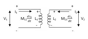
Fig 13 Current entering one dot and leaving other
 ⎼⎼⎼⎼⎼⎼⎼⎼1
 ⎼⎼⎼⎼⎼⎼⎼⎼2
- When current is entering in both dots
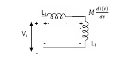
Fig 14 Current enters both dots
If M12= M21= M


II. When current leaves both dots
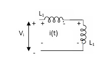
Find 
Fig 15 Current Leaving both dots


III. When current enters from L1 and leaves L2
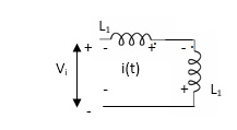
Find 
Fig 16 current enters from L1 and leaves L2


IV. When current leaves L2and enters L1
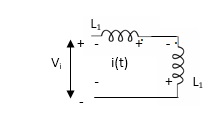
Fig 17 current leaves L2and enters L1

Key takeaway
The current entering the dot is taken as positive.
Example 1. Find 
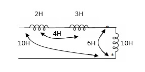
 = 2H + 3H +10H - 2(10H)+ 2(4H) + 2(6H)
= 15H + - 20H + 20H
= 0
Example 2. Find 
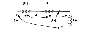
 5H + 6H + 9H - 2(1H) -2(5H) -2(3H)
= 2H
PARALLEL COMBINATION: -
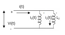

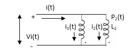

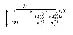


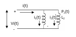

Q) Calculate the phasor currents I1 and I2 in the circuit of Figure below
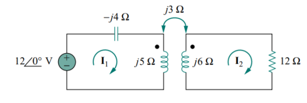
A) For coil 1, KVL gives
−12 + (−j4 + j5) I1 − j3I2 = 0
j I1 − j3I2 = 12
For coil 2, KVL gives
−j3I1 + (12 + j6) I2 = 0
I1 =  = (2-4j) I2
(j2 + 4 − j3) I2 = (4 − j) I2 = 12
I2 = A
A
I1 = (2 − j4) I2 =  )
)  ) =
) =  A
A
Q) Calculate the mesh currents in the circuit of Figure below
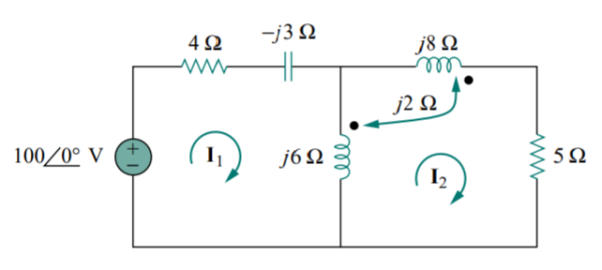
A) The mutual voltage is V1 = −2j I2.
For mesh 1 applying KVL we have
−100 + I1(4 − j3 + j6) − j6I2 − j2I2 = 0
100 = (4 + j3) I1 − j8I2
Applying the dot convention gives the mutual voltage as V2 = −2j I1. Also, current I2 sees the two coupled coils in series; since it leaves the dotted terminals in both coils. Therefore, for mesh 2, KVL gives
0 = −2j I1 − j6I1 + (j6 + j8 + j2 × 2 + 5) I2
0 = −j8I1 + (5 + j18) I2


The determinants are
 =
=  = 30+j87
 =
=  = 100(5+j18)
 =
=  = j800
Thus, we obtain the mesh currents as
I1 =  =
=  =
=  = 20.3
I2 =  =
=  =
=  = 8.693
Q) Estimate the currents for the circuit in figure using the Kirchhoff’s laws
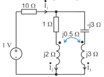
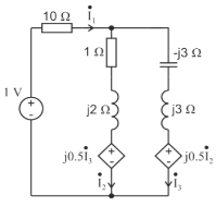
A) It can be seen that the mutual inductance jωM is given as mutual resistance jωM= j0.5 Ω
Firstly, we are going to create an equivalent circuit by replacing the mutual inductance with dependent source. Since both currents  and
and  enter the dots, the dependent sources are with plus sign. Next, we write the system of equations:

1-0.5 =10
=10 +(1+j2)
0.5 -0.5
-0.5 = -(1+j2)
  +0
+0 

 =
= 
The determinants are
 =
=  =10.25+j10
 =
=  = 1+j
= 1+j
 =
=  = -j0.5
 =
=  = 1+j1.5
The value of currents will be
 =
=  =
=  =
= 
 =
=  =
=  =
= 
 =
=  =
=  =
= 
Q) Estimate the currents for the circuit in figure using nodal analysis.
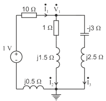
A)  =
=  +
+ 
The node voltage then becomes
 =
= 
The value of currents will be
 =
=  =
= 
 =
=  =
= 
 =
=  =
= 
Q) Estimate the currents for the circuit in figure using mesh analysis.
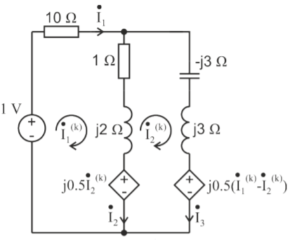
A) First, we should estimate the branch currents with the mesh current


1-j0.5 =
=  (10+1+j2)
1=
J0.5 -j0.5
-j0.5 +j0.5
+j0.5 =
= (1+j2)
-

The determinants are
 =
=  = 10.25+j10
 =
=  = 1+j
= 1+j
 =
=  = 1+j1.5
The value of currents will be
 =
=  =
=  =
= 
 =
=  =
=  =
= 
The value of branch current will now be
 =0.099+j0.001A
 = 0.099+j0.001-0.123-j0.026=-0.024-j0.025A
 0.123+j0.026A
A transformer is a stationary device which works on the principle of Mutual Induction. It is used to transform electric power from one circuit to another having same frequency. It can lower or higher the value of voltage in any circuit but in correspondence to change in current.
An ideal transformer has no losses i.e., its winding has no magnetic leakage and no ohmic resistance. Hence, an ideal transformer has only two purely inductive coils wound on a loss-free core.
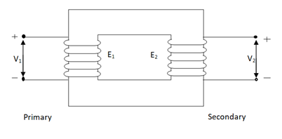
Fig 18. Ideal Transformer
For above transformer when secondary is open and primary is having input sinusoidal voltage V1. An alternating current flow due to difference in potential. As primary coil is purely inductive so, Iµ current is drawn through it. This current is very small and logs V1 by 900.
The current Iµ produces magnetic flux φ and hence are in same phase. The flux is linked with both the windings and hence, self-induced emf is produced E1 which is equal and opposite of V1. Similarly, E2 is induced in secondary which is mutually induced emf E2 is proportional to rate of change of flux and number of secondary windings.
The phasor is shown below.
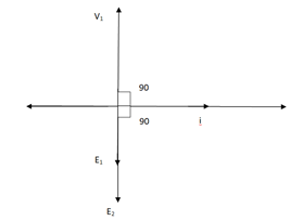
Fig 19 Phasor for Ideal Transformer
Emf Equation of Transformer:
N1 = No of primary turns
N2 = No of secondary turns
Φm = max flux in cone (wb)
Φm = Bm x A
f = Frequency of input(ac) Hz
Average rate of change of flux
= Φm / ¼
= 4 ΦmF volts
Average emf per turn = 4F ΦmV
As Φ varies sinusoidally rms value of induced emf is given as
Form factor = r.m.s value / average value = 1.11
r.m.s value of emf/turn = 1.11 x 4f Φm
= 4.44 f Φm volt
r.m.s value of induced emf in primary winding
= (induced emf/turn) x No of primary turns
E1 = 4.44 fN1 Φm
E1 = 4.44 fN1BmA
r.m.s emf induced in secondary
E2 = 4.44 fN2 Φm
E2 = 4.44 fN2BmA
E1/E2 = N1/N2 = K
K – voltage transformation
(i). If N2 > N1 i.e., K > 1 STEP UP TRASFORMER
(II). If N1 > N2 i.e., K<1 STEP DOWN TRASFORMER
Key takeaway
FOR Ideal Transformer
V1 I1 = V2 I2 = 1/K
Hence, current is inversely proportional to the voltage transformation ratio.
Examples
Q1>. A 25 KVA transformer has 500 turns on primary and 50 on secondary. The primary is connected to 2000V, 50 Hz supply. Find full load primary and secondary currents, the secondary emf and max flux in core. Neglect leakage drop and no load primary current.
Sol: K = N2/N1 = 50/500 = 1/10
I1 = 25,000/2000 = 12.5 A
I2 = I1/K = 10 x 12.5 A = 125 A
Emf/turn on primary side = 2000/500 = 4 V
E2 = KE1
E2 = 4 x 50 = 200 v
E1 = 4.44fN1 Φm
2000 = 4.44 x 50 x 500 x Φm
Φm = 18.02 m Wb
Equivalent Circuit
The basic transformer and its equivalent circuit both are shown below,
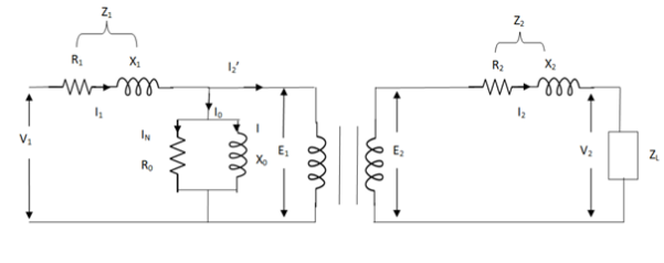
Fig 20 Equivalent Transformer Circuit
Iµ - magnetising component of current
Iw = working component
R0 – Non- inductive resistance
I0 – No load current
X0 = E1/I0. R0 = E1/Iw
E2/E1 = N2/N1 = K
E’2 = E2/K = E1
V’2 = V2/K
I’2 = K I2
The total equivalent circuit is again given as,
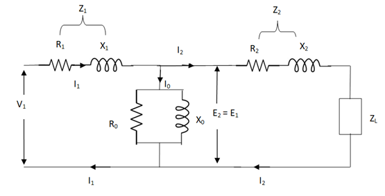
Fig 21 Transformer Equivalent Circuit
But the above circuit is exact equivalent but harder to solve so, it can be further simplified as,
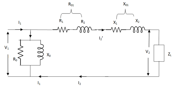
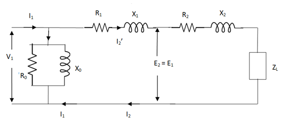
Fig 22 Reduced Equivalent Circuit
Z = Z1 + Zm || (Z’2 + Z’L)
= Z1 + Zm (Z’2 + Z’L)/Zm + (Z’2 + Z’L)
Z’2 = R’2 + jX’2
Zm = impedance of exciting circuit
V1 = I1[ Z1 + Zm (Z’2 + Z’L) / Zm + (Z’2 + Z’L)]
Example
Q1). In a 50 KVA, 2200/200 V, 1-φ transformer, the iron and full-load copper losses are 400 W and 450 W respectively. Calculate n at unity power factor on (i). Full load (ii). Half-full load?
Sol. (i). Total loss = 400 + 450 = 850 W
F.L output at unity power factor = 50 x 1
= 50 KVA
n = 50 / 50 + .850 = 50/50.850 = 0.98 = 98%
(ii). Half full load, unity pf
= 50 KVA/2 = 25 KVA
Cu loss = 400 x (1/2)2 = 100 W
Iron loss is same = 450 W
Total loss = 100 + 450 = 550 W
n = 25/25 + 0.55 = 25/25.55 = 0.978 = 97.8 %
Q>. A 40 KVA 440/220 V, 1- φ, 50 Hz transformer has iron loss of 300 W. The cu loss is found to be 100 W when delivering half full-load current. Determine (i) n when delivering full load current at 0.8 lagging pf (ii) the percentage of full-load when the efficiency will be max.
Sol. Full load efficiency at 0.8 pf
= 40 x 0.8/(40 x 0.8) + losses
Full load cu loss = (440/220)2 x 100
= 400 W
Iron loss = 400 + 300
= 700 W
n = 40 x 0.8/(40 x 0.8) + 0.7 = 97.8 %
(ii). KVA for maximum / F.L KVA = √ iron loss / F.L cu loss
= √300/400 = 0.866
Q) Two transformers are required for a Scott connection operating from 410 V 3-Ø supply for supplying two 1-Ø furnaces at 200 V on the two-phase side. If total output is 130 kVA, calculate secondary to primary turn ratio and the winding of each transformer?
Sol: For main Transformer
Primary voltage = 410 V
Secondary voltage = 200 V

Secondary current =  = 325 A
Primary current = 325 × 
= 153.54 A
For teaser Transformer
Primary volts =  = 355 V
Secondary volts = 200 V

Q) A delta-delta bank consisting of three 10kVA,2200/220v transformer supplies a load of 40kVA. If one transformer is removed, find the resulting V-V connection. Find total kVA rating of V-V bank and ratio of V-V bank to delta-delta transformer rating?
Sol: kVA rating of V-V bank = 2x10x0.866 = 17.32kVA
 =
=  = 0.577 = 57.7%
Q) A delta-delta bank consisting of three 10kVA,2200/220v transformer supplies a load of 40kVA. If one transformer is removed, find the resulting V-V connection. a) kVA load carried by each transformer b)% of rated load carried by each transformer.
Sol: As we already know  =
=  3
3
KVA load supplied by each transformer = 40/ 3 = 23.1kVA
% of rated load =  = 23.1/10 = 231 %
Q) Two transformer connected in open delta supply a 430kVA balanced load operating at 0.9 p.f lagging. The load voltage is 460v. What is the kVA supplied by each transformer?
Sol: kVA of each transformer = (430/2)/0.9 = 238.9kVA
The p.f of two transformers will be cos (30 -φ) and cos(30
 +φ)
+φ)
Cos φ=0.9
φ = 25.8
P1= kVA cos (30 -φ) = 238.9 x cos (30
 -25.8
-25.8 ) = 238.27kW
P2= kVA cos (30 +φ) = 238.9 x cos (30
 + 25.8
 ) =134.28kW
Q) Two, 1-Φ furnaces working at 110v are connected to 3000v, 3-Φ mains through Scott connected transformer. Calculate the line current in 3-Φ mains when the power taken by each furnace is 400 kW at a p.f of 0.8 lagging. Transformer has no losses.
Sol: K= 110/3000 = 0.0367
I2=400000/0.8x110 = 4545.5A
The 3-phase side is balanced as the load is balanced.
The primary phase current = 1.15kI2 = 1.15 x 0.0367 x 4545.5=191.84A
For star connection Iph=IL
IL= 191.84A
Q) Two 1-Ø transformers, one of 800 kVA and 400 kVA are connected in parallel to the same bus bars on primary side. Their no load secondary voltage 500 V and 510 V respectively. The impedance voltage of first is 8% and that of second is 5%. Assume ratio of resistance to reactance is same and equal to 0.4 in each. Calculate the cross current when secondary’s are connected in parallel?
Sol: The X/R is same for both; hence they do not have any phase difference.
Let secondary be 480 V
For full load IA = 800 ×  A
A
IB = 400 ×  A
A
ZA = 
ZB = 
The cross current is given as
IC =  A
A
References:
- M. E. Van Valkenburg, “Network Analysis”, Prentice Hall, 2006.
- D. RoyChoudhury, “Networks and Systems”, New Age International Publications, 1998.
- W. H. Hayt and J. E. Kemmerly, “Engineering Circuit Analysis”, McGraw Hill Education, 2013.
- C. K. Alexander and M. N. O. Sadiku, “Electric Circuits”, McGraw Hill Education, 2004.
- K. V. V. Murthy and M. S. Kamath, “Basic Circuit Analysis”, Jaico Publishers, 1999.