Unit - 3
Graph Theory
The description of networks in terms of their geometry is referred to as network topology. The adequacy of a set of equations for analysing a network is more easily determined topologically than algebraically.
Graph (or linear graph): A network graph is a network in which all nodes and loops are retained but its branches are represented by lines. The voltage sources are replaced by short circuits and current sources are replaced by open circuits. (Sources without internal impedances or admittances can also be treated in the same way because they can be shifted to other branches by E-shift and/or I-shift operations.)
Branch: A line segment replacing one or more network elements that are connected in series or parallel.
Node: Interconnection of two or more branches. It is a terminal of a branch. Usually, interconnections of three or more branches are nodes. Path: A set of branches that may be traversed in an order without passing through the same node more than once.
Loop: Any closed contour selected in a graph.
Mesh: A loop which does not contain any other loop within it.
Planar graph: A graph which may be drawn on a plane surface in such a way that no branch passes over any other branch. Non-planar graph: Any graph which is not planar.
Oriented graph: When a direction to each branch of a graph is assigned, the resulting graph is called an oriented graph or a directed graph.
Connected graph: A graph is connected if and only if there is a path between every pair of nodes. Sub graph: Any subset of branches of the graph.
Tree: A connected sub-graph containing all nodes of a graph but no closed path. i.e. it is a set of branches of graph which contains no loop but connects every node to every other node not necessarily directly. A number of different trees can be drawn for a given graph.
Link: A branch of the graph which does not belong to the particular tree under consideration. The links form a sub-graph not necessarily connected and is called the co-tree.
Tree compliment: Totality of links i.e. Co-tree.
Independent loop: The addition of each link to a tree, one at a time, results one closed path called an independent loop. Such a loop contains only one link and other tree branches. Obviously, the number of such independent loops equals the number of links.
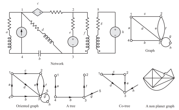
Fig 1 typical network with its graph, oriented graph, a tree, co-tree and a non-planar graph.
Tie set: A set of branches contained in a loop such that each loop contains one link and the remainder are tree branches.
Tree branch voltages: The branch voltages may be separated in to tree branch voltages and link voltages. The tree branches connect all the nodes. Therefore, if the tree branch voltages are forced to be zero, then all the node potentials become coincident and hence all branch voltages are forced to be zero. As the act of setting only the tree branch voltages to zero forces all voltages in the network to be zero, it must be possible to express all the link voltages uniquely in terms of tree branch voltages. Thus, tree branch forms an independent set of equations.
Cut set: A set of elements of the graph that dissociates it into two main portions of a network such that replacing any one element will destroy this property. It is a set of branches that if removed divides a connected graph in to two connected sub-graphs. Each cut set contains one tree branch and the remaining being links.
Node, Link and Brach Relation
Let B = Total number of branches in the graph or network
N = total nodes
L = link branches
Then N − 1 branches are required to construct a tree because the first branch chosen connects two nodes and each additional branch includes one more node.
Number of independent node pair voltages = N − 1 = number of tree branches.
Then L = B − (N − 1) = B − N + 1
Number of independent loops = B − N + 1
Subgraph enumeration problems are enumeration problems that given a graph G and a graph class S, output all subgraphs s of G satisfying S∈ S without duplicates. Subgraph enumeration problems are widely studied. Enumeration involves a huge number of solutions, thus enumeration algorithms are supposed to run in short time, with respect to the number of solutions N. For example, if an algorithm runs in O(N f) time for small f, other than prepro- cessing, we can consider the algorithm is efficient. In this case, we say that the algorithm runs in O(f) time per solution, or O(f) time for each solution. Further, the maximum computation time between two consecutive outputs called delay is also considered as a more efficiency of enumeration algorithms.
Note that delay will not be O(f) even if an algorithm runs in O(f) time per solution. Enumeration algorithms are widely studied in these days. Especially, the data mining area has a large amount of studies on pattern mining problem. The algorithms have to deal with huge databases and a huge number of solutions, thus there are great needs of the algorithm theory on efficient enumeration. As we show below, many recent studies focus on the development of small complexity algorithms. Compared to other algorithms, enumeration algorithms have some unique aspects.
For example, by operating only on the differences between the solutions, one can develop algorithms that run in time shorter than the amount of exact output. Other than this, since the recursion is much more structured compared to optimization, we can develop a non-trivial amortized analysis. As a consequent, researches on the numeration algorithms have great interests.
In what follows, we fix the input graph G= (V, E ), and let m=|E|,n=|V|. In the 1970s, Tarjan and Read studied a problem of enumerating spanning trees in the input graph. Their algorithm runs in O(m+n+mN ) time. Shioura, Tamura, and Uno is improved the complexity to O(n+m+N) time. Tarjan proposed an algorithm for enumerating all cycle in O((|V|+|E|)(|C(G)|+ 1)) time, where C(G) is all cycle improved the complexity to in O(m+Pc∈C(G)|c|) total time. They also presented an enumeration algorithm for all st-paths in the input graph Gin O(m+Pπ∈Pst(G)|π|) total time, where Pst(G) is all st-paths in G. Ferreira et al. Proposed an enumeration algorithm that enumerating all subtree having exactly kedges in Gin O(kN ) time. Wasa et al. [10] presented an improved version of Ferreira et al.’s problem in constant time delay when the input is a tree. As we see, speed up of enumeration algorithms have been intensively studied in long history. Compared to these studies, induced subgraph enumerations have not been studied well. Avis and Fukuda considered the connected induced subgraph enumeration problem. Their algorithm is based on reverse search, and runs in O(mnN) time. Uno proposed an enumeration algorithm for enumerating all chordless path connecting the given vertices sand tand all chordless cycle in O((m+n)N) time.
We address the problem of enumerating all induced subtrees in the given graph, Assume that the set of vertices in an induced subtree is S. Then, V\Sis a feedback vertex set of G. Feedback vertices are also fundamental graph objects and their enumeration problem is equivalent to that of induced subtrees. If the input graph Gis a tree, the connected induced subgraph of G is a subtree. Thus, Wasa et al.’s shows that the induced subtree enumeration problem can be solved in constant time delay when the input graph is a tree.
Tree is a simple graph class, so we are motivated whether we can do better in more general graph classes with non-trivial algorithms. As a main result of this paper, we propose an algorithm for the k-degenerate graph case. The algorithm runs in O(k) time per solution, after (|V|+|E|) preprocessing time. The algorithm starts from the empty subgraph, and adds a vertex recursively to enlarge the induced subtree. The vertex to be added has to be adjacent to the current induced subtree, and has not to make a cycle. By using the degeneracy, we efficiently maintain the addible vertices, and the time complexity is bounded by a sophisticated amortized analysis. Real world graphs usually have small degeneracies, or only few vertex removals result small degeneracies, the algorithm is expected to be efficient in practice
Let G= (V, E) be an undirected graph, where Vis the set of vertices and E⊆V2 is the set of edges. We assume that G is simple and finite. We denote by (u, v) the edge connecting u and v. For any vertices u, v of V, we say that u and v are adjacent to each other if (u, v) ∈E. We denote by NG(u) the set of all vertices adjacent to u in G. We define the degree dG(u) of u in Vas the number of vertices adjacent to u. In what follows, if it is clear from context, we omit the subscript G. A path in G is a sequence of distinct vertices π (u, v) = (v1=u, . . . , vj=v), such that viand vi+1 are adjacent to each other for 1 ≤i < j. If there is π (u, v) in G, we say that the path connects u and v. The length of path π(u, v) is the number of vertices in π(u, v) minus one. For any path π(u, v) of length larger than one, π(u, v) is called a cycle if u=v. We say that G is connected if there is a path connecting any pair of vertices in G. G is a tree if G has no cycle and is connected
K-degenerate graphs
A graph G is k-degenerate if any its induced subgraph of G has a vertex whose degree is less than or equal to k. The degeneracy of G is defined as the smallest k satisfying the definition of k-degenerate graphs. Examples of graph classes with constant degeneracy include trees, grid graphs, outerplanar graphs, and planer graphs, thus degenerate graph is a large class of sparse graphs. These degeneracy are 1, 2, 2, and 5, respectively. From the definition of k-degeneracy, we obtain a vertex sequence (u1,...,u|V|) satisfying the condition ∀1≤i≤ |V|,|{uj∈N(ui)|i < j ≤ |V|}| ≤ k···(⋆). This condition (⋆) implies that there exists an ordering among vertices of G such that for any vertex u, the number of vertices adjacent to u larger than it is at most k. Hereafter we assume that the vertices are indexed in this ordering. We say u < v (u > v, respectively) if the index of u is smaller than v(u is larger than v, respectively) with respect to this ordering. An example of the ordering satisfying (⋆). Matula and Beck proposed an algorithm for obtaining the degeneracy of G and the ordering satisfying (⋆). By iteratively choosing the smallest degree vertex and removing it from G, their algorithm finds such an ordering in O(|V|+|E|) time.
It is also known as augmented incidence matrix. The element node incidence matrix A indicates in a connected graph, the incidence of elements to nodes. It is an N × B matrix with elements of An = (akj)
akj = 1, when the branch bj is incident to and oriented away from the kth node. = −1, when the branch bj is incident to and oriented towards the kth node. = 0, when the branch bj is not incident to the kth node. As each branch of the graph is incident to exactly two nodes,

For j=1, 2, 3……..B
That is, each column of An has exactly two non-zero elements, one being +1 and the other −1. Sum of elements of any column is zero. The columns of An are linearly dependent. The rank of the matrix is less than N. Significance of the incidence matrix lies in the fact that it translates all the geometrical features in the graph into an algebraic expression. Using the incidence matrix, we can write KCL as
An iB = 0, where iB = branch current vector. But these equations are not linearly independent. The rank of the matrix A is N − 1. This property of An is used to define another matrix called reduced incidence matrix or bus incidence matrix.
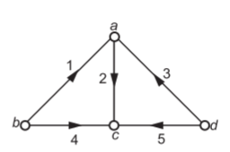
Fig 2 Oriented Graph of a network
The incidence matrix for above graph will become

An
Note that sum of all elements in each column is zero
Any node of a connected graph can be selected as a reference node. Then the voltages of the other nodes (referred to as buses) can be measured with respect to the assigned reference. The matrix obtained from An by deleting the row corresponding to the reference node is the element bus incident matrix A and is called bus incidence matrix with dimension (N − 1) × B. A is rectangular and therefore singular. In An, the sum of all elements in each column is zero. This leads to an important conclusion that if one row is not known in A, it can be found so that sum of elements of each column must be zero.
From A, we have A iB = 0, which represents a set of linearly independent equations and there are N − 1 independent node equations. For the graph shown in Figure 2, with d selected as the reference node, the reduced incidence matrix is

An
Note that the sum of elements of each column in A need not be zero. Note that if branch current vector,
jB= 
Then A iB = 0 representing a set of independent node equations. Another important property of A is that determinant AAT gives the number of possible trees of the network. If A = [At : Ai] where At and Ai are sub-matrices of A such that At contains only twigs, then det At is either + 1 or −1.
To verify the property that det AAT gives the number of all possible trees, consider the reduced incidence matrix A of the example considered. That is,

A
Det AAT =  =8
=8
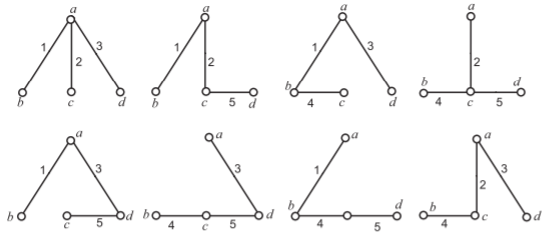
Fig 3 All possible tree for Fig 2
To verify the property that the determinant of sub matrix At of A = At; Ai is +1 or −1. For tree [2, 3, 4]

A = At; Ai
For another tree [2, 4, 5]

A = At; Ai
Det Ai =  = -1
= -1
Tie Set Matrix
From the knowledge of the basic loops (tie-sets), we can obtain loop matrix. In this matrix, the loop orientation is to be the same as the corresponding link direction. In order to construct this matrix, the following procedure is to be followed.
1. Draw the oriented graph of the network. Choose a tree.
2. Each link forms an independent loop. The direction of this loop is same as that of the corresponding link. Choose each link in turn.
3. Prepare the tie-set matrix with elements bij.
Where bij = 1, when branch bj in loop i and is directed in the same direction as the loop current.
bij=-1, when branch bj in loop i and is directed in the opposite direction as the loop current.
bij=0, when branch bj is not in loop i.
Tie-set matrix is an i x b matrix
For example, let us consider
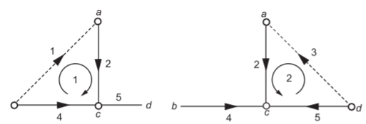
Selecting (2, 4, 5) as tree, the co-tree is (1, 3). The tie set will now be

A = At; Ai
VB = 
Then MVB gives the following independent loop equations: v1 + v2-v4 = 0
v2 + v3-v5=0
= 0 Looking column wise, we can express branch currents in terms of loop currents. This is done by the following matrix equation as
JB=MTIL
The above matrix equation gives
J1=i1
J2=i1+i2
J3=i2
J4=-i1-i2
Note that J stands for branch current while i stands for loop current. In this matrix
(i) Each row corresponds to an independent loop. Therefore, the columns of the resulting schedule automatically yield a set of equations relating each branch current to the loop currents.
(ii) (ii) As each column expresses a branch current in terms of loop currents, the rows of the matrix automatically yield the closed paths in which the associated loop currents circulate. Expressions for branch currents in terms of loop currents may be obtained in matrix form as JB=MTIL
M is the Tie Set Matrix of L x B
Cut Set Matrix
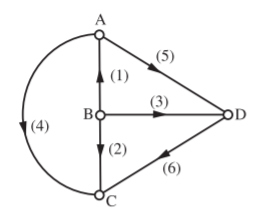
Fig 4 Directed Graph
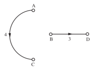
Fig 5 Two separate graph created by the cut set [1,2,5,6]
6} A cut-set of a graph is a set of branches whose removal, cuts the connected graph into two parts such that the replacement of any one branch of the cut-set renders the two parts connected. For example, two separated graphs are obtained for the graph of Fig. 4 by selecting the cut-set consisting of branches [1, 2, 5, 6]. These separated graphs are as shown in Fig.5. Just as a systematic method exists for the selection of a set of independent loop current variables, a similar process exists for the selection of a set of independent node pair potential variable.
It is already known that the cut set is a minimal set of branches of the graph, removal of which divides the graph in to two connected sub-graphs. Then it separates the nodes of the graph in to two groups, each being one of the two sub-graphs. Each branch of the tie-set has one of its terminal incidents at a node on one sub-graph. Selecting the orientation of the cut set same as that of the tree branch of the cut set, the cut set matrix is constructed row-wise taking one cut set at a time. Without link currents, the network is inactive.
In the same way, without node pair voltages the network is active. This is because when one twig voltage is made active with all other twig voltages are zero, there is a set of branches which becomes active. This set is called cut-set. This set is obtained by cutting the graph by a line which cuts one twig and some links. The algebraic sum of these branch currents is zero. Making one twig voltage active in turn, we get entire set of node equations. This matrix has current values
qi,j = 1, if branch J is in the cut-set with orientation same as that of tree branch.
qi,j = 1, if branch J is in the cut-set with orientation opposite to that of tree branch.
qi,j = 0, if branch J is not in the cut-set. And dimension is (N-1) x B
Row-by-row reading, it gives the KCL at each node and therefore we QJB=0.
The procedure to write cut-set matrix is as follows:
(i) Draw the oriented graph of a network and choose a tree.
(ii) Each tree branch forms an independent cut-set. The direction of this cut-set is same as that of the tree branch. Choose each tree branch in turn to obtain the cut set matrix. Isolate the tree element pairs and energize each bridging tree branch. Assuming the bridging tree branch potential equals the node pair potential, thus regarding it as an independent variable.
(iii) Use the columns of the cut-set matrix to yield a set of equations relating the branch potentials in terms of the node pair potentials. This may be obtained in matrix for VB=QTEN
Where v and e are used to indicate branch potential and node voltage respectively. In the example shown in Fig 6, (3, 4, 5) are tree branches. Links are shown in dotted lines. If two tree branch voltages in 3 and 4 are made zero, the nodes b and d are at the same potential. Similarly, the nodes a and c are at the same potential. The graph is reduced to the form shown in Fig. 7 containing only the cut-set branches. Then, we have
i5-i1-i2-i6=0
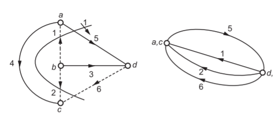
Fig 6 and Fig 7 Cut set
Similarly, by making only e4 to exist (with e5 and e3 zero), the nodes a, b and c are at the same potential, reducing the graph to the form shown in figure 8. Thus,
I4+i2+i6=0
This corresponds to cut set 2 as shown in Fig.9
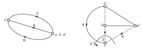
Fig 8 and Fig 9 Cut Set
For the remaining cut-set, e4 and e5 are made zero as in Fig 10. e3 is active and hence, the nodes a, b and c are at the same potential. Thus
i1+i3+i2=0
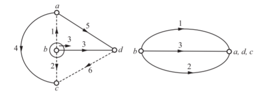
Fig 10 Cut Set
Therefore, the cut set schedule is

 =
= 
 =Q
=Q
The equations for QJB are
-J1-J2-J5+J6=0
J2+J4+J6=0
J1+J2+J3=0
Looking column-wise, we can express branch voltages in terms of node pair voltages as
v1=-e1+e3
v2=-e1+e2+e3
v3=e3
v4=e2
v5=e1
v6=-e1+e2
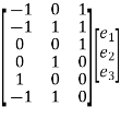 =VB
=VB
VB= QT EN
Q) Draw the graph, one tree and its co-tree for the circuit shown in the figure?
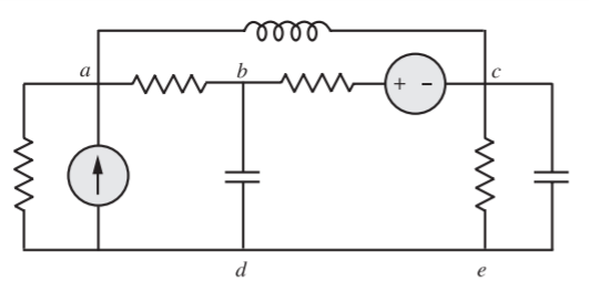
A) We find that there are four nodes (N = 4) and seven branches (B = 7). The graph is then drawn and appears as shown in Figure below. It may be noted that node d represented in the graph represents both the nodes d and e.
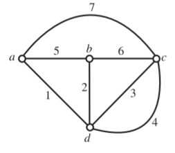
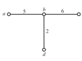
Fig Graph Fig Tree
Figure below shows one tree of graph shown in Figure above. The tree is made up of branches 2, 5 and 6. The co-tree for the tree of Figure above is shown below.
The co-tree has L = B − N +1=7 − 4+1=4 links.
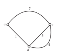
Fig Co Tree
Q) Obtain the corresponding incidence matrix for the circuit shown in following figure?
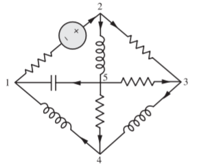
A) The network shown above has 5 nodes and 8 branches. The corresponding graph appears in the following figure.
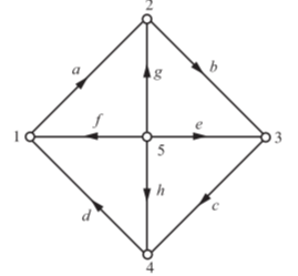
The incidence matrix is formed by following the rule:
The entry of the incidence matrix,
ak = 1, if the current of branch k leaves the node i
= 1, if the current of branch enters node i
= 0, if the branch k is not connected with node i
Incident Matrix
Nodes | Branches | |||||||
| a | b | c | d | e | f | g | h |
1 | +1 | 0 | 0 | -1 | 0 | -1 | 0 | 0 |
2 | -1 | +1 | 0 | 0 | 0 | 0 | -1 | 0 |
3 | 0 | -1 | +1 | 0 | -1 | 0 | 0 | 0 |
4 | 0 | 0 | -1 | +1 | 0 | 0 | 0 | -1 |
5 | 0 | 0 | 0 | 0 | +1 | +1 | +1 | +1 |
In matrix form we write it as
A5 = 
Where subscript 5 indicates that there are five nodes in the graph. It may be noted that from a given incidence matrix, the corresponding graph can be drawn.
Q) For the incidence matrix shown below, draw the graph?


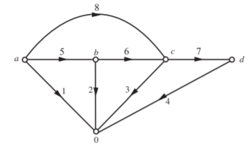
A) Observing the matrix, it can be seen that it is a reduced incidence matrix. Branches 1, 2, 3 and 4 are to be connected to the reference node. Branch 5 appears between the nodes a and b, 6 between b and c, 7 between c and d, 8 between a and c. With this information, the oriented graph is drawn as shown below. Orientation is +1 for an arrow leaving a node d -1 for an arrow entering a node.
Q) Draw the graph of a network of whose incidence matrix is


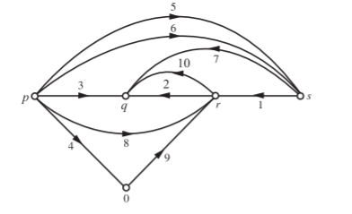
A) Sum of the elements in columns 4, 9 are not zero. Therefore, the given matrix is a reduced matrix. Taking 0 as reference node, the oriented graph is as shown in Figure after making the nodes in an order.
Q) For the graph shown in Figure, write the incidence matrix. Express branch voltage in terms of node voltages and then write a loop matrix and express branch currents in terms of loop currents.
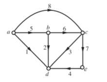
A) With the orientation shown in Figure above, the incidence matrix is prepared as shown below


Branch voltages in terms of node voltages are
V1=ec-ed
V2=eb-ed
For loop (tie-set) matrix,
L= B-N+1=8- 5+1=4.
With twigs (1, 2, 3, 4), we have chords (links) (5, 6, 7, 8) and the corresponding tree is as shown in Fig. Introducing the chords one at a time, the tie-set matrix is prepared as below
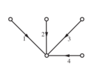


The branch currents in terms of loop currents are J1 = −i1 − i4, J2 = i1 − i2 etc.
Q) For the network shown below, determine the number of all possible trees. For a tree consisting of (1, 2, 3) (i) draw tie set matrix (ii) draw cut-set matrix.
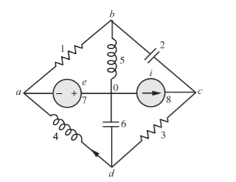
A) If the intention is to draw a tree only for the purpose of tie-set and cut-set matrices, the ideal current source is open circuited and ideal voltage source is short circuited. The oriented graph is drawn for which d is the reference.

A=
Det AAT =  +
+  = 12
= 12
Therefore, possible number of trees = 12
The corresponding graph, tree, co-tree, and loops 1, 2, 3 are shown below
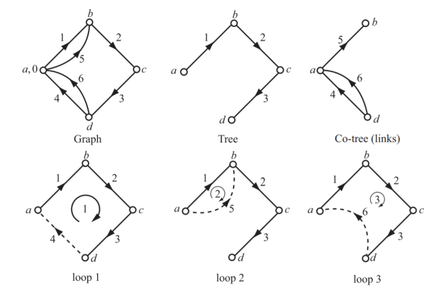
(i) Tie-set matrix for twigs (1, 2, 3) is


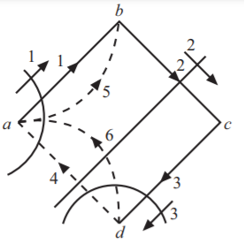
(ii) Cut-set matrix is


Q) For the circuit shown below, write a tie-set schedule and then find all the branch currents and voltages?
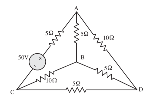
A) Figure below shows the graph for the network. Also, a possible tree and co-tree are shown in Fig. Co-tree is in dotted.
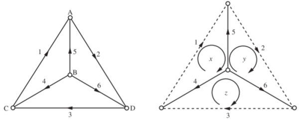
First, the tie-set schedule is formed and then the tie-set matrix is obtained.
Loop Currents | Branch numbers | |||||
1 | 2 | 3 | 4 | 5 | 6 | |
x | +1 | 0 | 0 | +1 | -1 | 0 |
y | 0 | +1 | 0 | 0 | +1 | -1 |
z | 0 | 0 | +1 | -1 | 0 | +1 |
Tie-set matrix is
M= 
The branch impedance matrix is
ZB = 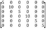
EB = 
The loop impedance matrix is
ZL = MZBMT
ZL=  +
+ 
ZL=  +
+ =
= 
MEB= 
The loop equations are obtained using the equation
ZLIL= MEB

x=4.1666A
y=1.1666A
z=2.5A
The branch currents are computed using the equations
IB=MTIL
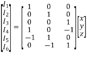
I1 = x = 4.1666 A, I2 = y = 1.6666 A, I3 = z = 2.5 A, I4 = x − z = 1.6666 A, I5 = −x + y = −2.5 A, I6 = −y + z = 0.8334 A
The branch voltages are computed using the equation
VB = ZBIB − EB
 =
= 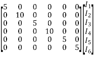 -
-
Hence, V1 = 5I1 − 50 = 29.167 V,
V2 = 10I2 = 16.666 V
V3 = 5I3 = 12.50 V
V4 = 10I4 = 16.666 V
V5 = 5I5 = −12.50 V
V6 = 5I6 = 4.167 V
Q) Find the tie-set matrix and loop currents for the circuit shown below
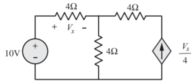
A) In the circuit, 4 Ω in series with current source is shorted (as it is trivial), the graph is as shown in Figure with 1 as tree branch and 2 as link.
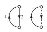
Using the equation, MZBMTIL = MEB − MZBIB with M = [1 1], we have
MZBMT = 
 =8
=8
MEB − ZBIB =  (
( ) =10-Vx
8I1 = 10 − Vx
But Vx = 4I1
8I1 = 10 − 4I1
I1 = 5/6A
As I1 = Vx/4 − I2
I2 = 5/6A
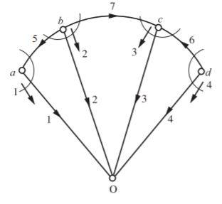
Q) For the given cut-set matrix, draw the oriented graph

A) Data from the matrix: B = 7, Nt = 5, N = 4, L = 3. Tree branch voltages are e1 = v1, e2 = v2, e3 = v3 and e4 = v4. Therefore, all these are connected to reference node. Individual cut-sets are

Which indicates that 5 is common to a and b, 7 is common to b and c, 6 is common to c and d.
Q) Solve for branch currents and branch voltages.
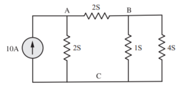
A) The oriented graph for the network is shown below. A possible tree and cotree with fundamental cut-sets are as shown.

Cut Set
Tree Branch Voltage | Branch number | |||
1 | 2 | 3 | 4 | |
e1 | 1 | 0 | -1 | 0 |
e2 | 0 | 1 | -1 | 1 |
Cut-set matrix:
Q = 
Branch admittance matrix:
YB = 
Cut-set admittance matrix:
YN = QYBQT
YN= 
YN= 
Equilibrium equations: YN EN = QIB
 =
= 
e1= -70/24V
e2= 20/24V
Branch voltage are found using the matrix equation: VB= QTEN
 =
= 
V1= -2.91V
V2= 0.833V
V3= 2.084V
V4= 0.833V
Branch currents are found using the matrix equation JB= YBVB−IB
 =
= 
I1= 4.166A
I2 = 0.833A
I3= 4.168V
I4= 3.333V
Q) For the oriented graph shown, express loop currents in terms of branch currents for an independent set of columns as those pertinent to the links of a tree:
(i) Composed of 5, 6, 7, 8
(ii) Composed of 1, 2, 3, 6
Verify whether the two sets of relations for i’s in terms of j’s are equivalent. Construct a tie-set schedule with the currents in the links 4, 5, 7, 8 as loop currents and find the corresponding set of closed paths
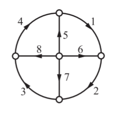
A) For first set
Loop No. | Branch Number | |||||||
1 | 2 | 3 | 4 | 5 | 6 | 7 | 8 | |
1 | 1 | 0 | 0 | 0 | 1 | -1 | 0 | 0 |
2 | 0 | 1 | 0 | 0 | 0 | 1 | -1 | 0 |
3 | 0 | 0 | 1 | 0 | 0 | 0 | 1 | -1 |
4 | 0 | 0 | 0 | 1 | -1 | 0 | 0 | 1 |
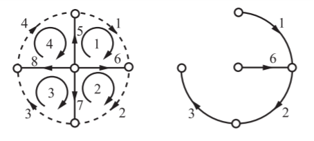
B=5,6,7,8
L=1,2,3,4
Then for second set of the mesh currents indicated for the first set we have
J4=i4
J5=i1-i4
J7=i3-i2
J8=i4-i3
By applying KCL we have
i1=J1=J4+J5
i2=J2=J3-J7
i3=J3=J4-J8
i4=J4
Thus, the two sets of relations for i’s in terms of J’s are equivalent. The tie-set schedule with the currents in links 4, 5, 7, 8 as loop currents.
Loop No. | Branch Number | |||||||
1 | 2 | 3 | 4 | 5 | 6 | 7 | 8 | |
1 | 1 | 0 | 0 | 0 | 1 | -1 | 0 | 0 |
2 | 0 | -1 | 0 | 0 | 0 | -1 | 1 | 0 |
3 | 0 | -1 | -1 | 0 | 0 | -1 | 0 | 1 |
4 | 1 | 1 | 1 | 1 | 0 | 0 | 0 | 0 |

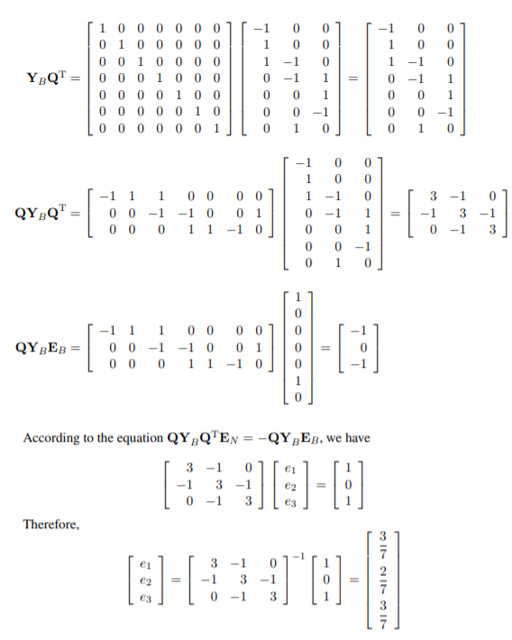
Q) In the graph shown in Figure, the ideal voltage source e = 1 V. For the remaining branches each has a resistance of 1 Ω with O as the reference. Obtain the node voltage e1, e2 and e3 using network topology.
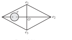
A)
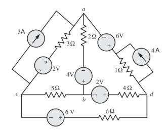
Q) For the circuit shown in Figure, for a tree consisting of ab, bc, cd form a tie-set schedule and obtain equilibrium loop equations. Choose branch numbers same as their resistance values. Solve for loop currents
A) The oriented graph is
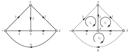
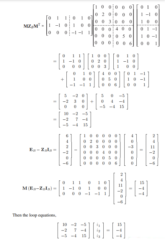
Tree with nodes ab, bc, cd and links are shown in line. The tie set matrix is


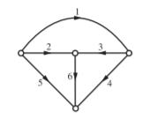
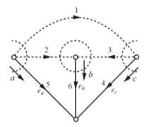
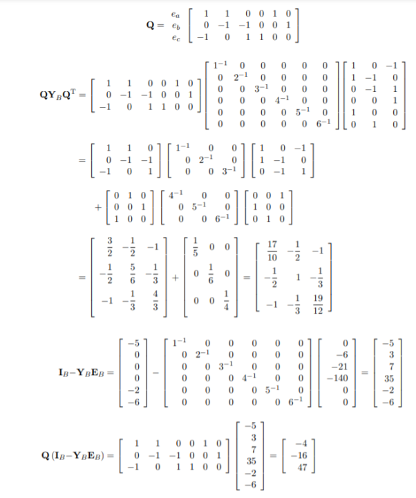
Q) For the network shown in Figure, prepare a cut-set schedule and obtain equilibrium equations. Number the branches by their ohmic values.
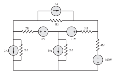
A) Numbering the branches same as those of ohmic values, the oriented graph is as shown in Figure. Choosing 4, 5, 6 as tree branches, the tie set schedule is as shown below

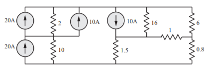
Q) Device a tree for the circuit shown in Figure, for which all the currents pass through 1 Ω. For this tree write the tie-set matrix to obtain equilibrium equations.
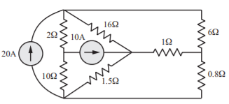
A) The network can be re drawn as shown below

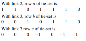
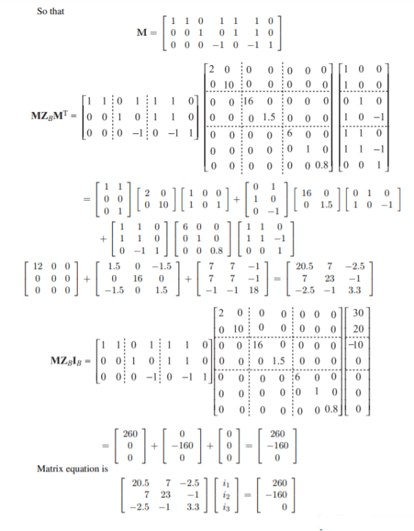
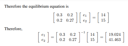
Q) For the circuit shown in Figure, construct a tree in which v1 and v2 are tree branch voltages, write a cut-set matrix and obtain equilibrium equations. Solve for v1
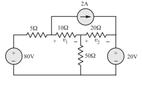
A) The circuit can be redrawn as
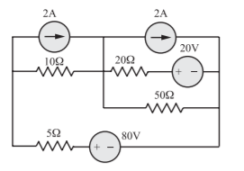
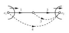
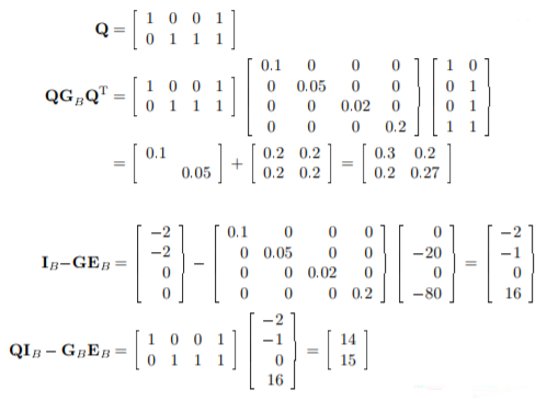
With v1 and v2 as tree branch voltages the graph is as shown in Figure, with tree branches with full lines and the links in dotted line
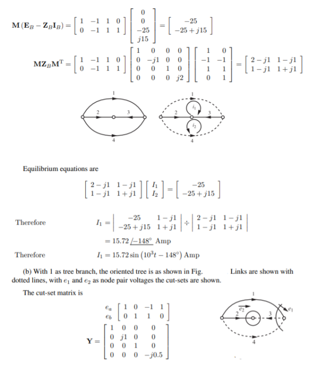
Q) (a) Construct a tree for the circuit shown in Figure so that i1 is a link current. Assign a complete set of link currents and find i1(t).
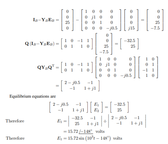
(b) Construct another tree in which v1 is a tree branch voltage. Assign a complete set of tree branch voltages and find v1(t)v. Take i(t) = 25 sin 103t Amp, v(t) = 15 cos 103(t)
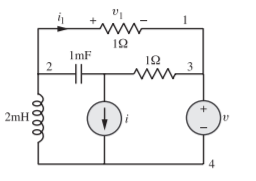
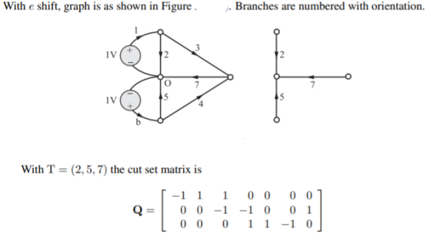
A) (a) The circuit after I shift is as shown in Fig.
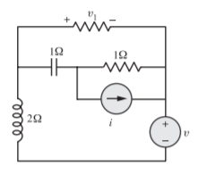
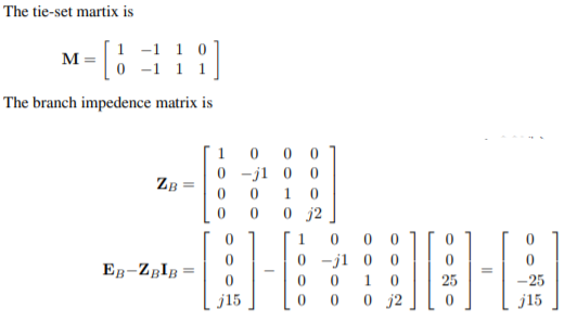
The oriented graph is as shown below. With branches as numbered, and 1 as a link the tree is as shown. Links are shown in dotted line (links are 1 and 4). The tie-set matrix is
References:
- M. E. Van Valkenburg, “Network Analysis”, Prentice Hall, 2006.
- D. RoyChoudhury, “Networks and Systems”, New Age International Publications, 1998.
- W. H. Hayt and J. E. Kemmerly, “Engineering Circuit Analysis”, McGraw Hill Education, 2013.
- C. K. Alexander and M. N. O. Sadiku, “Electric Circuits”, McGraw Hill Education, 2004.
- K. V. V. Murthy and M. S. Kamath, “Basic Circuit Analysis”, Jaico Publishers, 1999.