Unit - 5
Two Port Networks
Open circuit impedance parameters
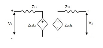
The Z parameters of a two-port for the positive directions of voltages and currents may be defined by expressing the port voltages V1 and V2 in terms of the currents I1 and I2. Here V1 and V2 are dependent variables, and I1, I2 are independent variables. The voltage at port 1-1’ is the response produced by the two currents I1 and I2. Thus,
Z-parameter:
v1 = Z11I1 + Z12I2
v2 = Z11I1 + Z22I2
 =
= 
Z11 =  I2=0
I2=0
Z12 =  I1=0
I1=0
Z21 =  I2=0
I2=0
Z22 =  I1=0
I1=0
 I1 and I2 are excitations at port 1 & 2 respectively.
 V1 and V2 are the responses at port 1 and 2 respectively.
Equivalent circuit:
Symmetry:
 I2=0 =
 I1 = 0
Z11 = Z22
Reciprocal two port N/W:-
 I2=0=
I2=0=  I1=0
I1=0
Z12 = Z21
I1& I2 should be independent
Que 1.
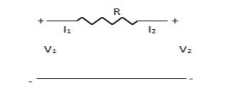
Find Z-parameter
Solution: I1 = -I2
Current dependent so Z-parameter doesn’t exist
Que 2.
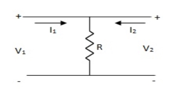
Find z-parameter
Solution: V1 =R (I1 + I2)
V2 = R (I1 + I2)
Z11 = Z12 = Z21 = Z22 = R
Que 3.
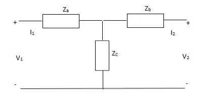
Solution: V1 = I1Za + I1Zc + I2Zc
= (Za + Zc)I1 + ZcI2
V2 = I2Zb + I2Zc + I1Zc
= (Zb + Zc)I1 + ZcI1
Z11 = (Za + Zc)
Z12 = Zc = Z21
Z22 = (Zb + Zc)
Que 4.
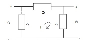
Solution: V1 = Za(I1 - I)
(I - I1)Za+ IZc+ Zb(I + I2) = 0
I(Za + Zb + Zc) – I1Za + I2Zb = 0
I = 
V1 = ZaI1 - Za
=  I1 + I2
V2 = Zb(I2 + I)
= ZbI2 + Zb
=  I2 + I2
Z11 = 
Z12 = Z21 = 
Z22 = 
Can be solved by Y-A conversion
Que 1.
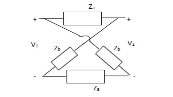
Solution:
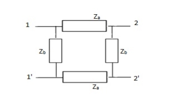
Z11 =  I2=0
I2=0
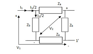
V1 -  (Za + Zb) = 0
 = Z11 =
Z21 =  I2=0
I2=0
V2 -  Zb +
Zb + Za = 0
 =
= 
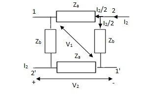
Z12 = 
Z22 = 
Que 2.
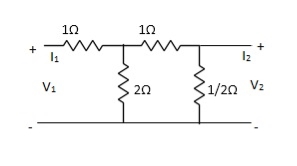
Find Z21?
Solution: Z21 =  I2=0
I2=0
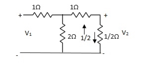
I1/2 = 
=  I1
I1
V2 =  I1/2
I1/2
=  ×
×  I1
I1
=  I1
I1
Z21 =  I2 = 0 =
  I1 Ω
I1 Ω
Que 3.
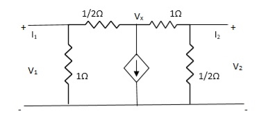
Solution: +
+  + 2V1 = 0
2Vx – 2V1 + Vx – V2 + 2V1 = 0
3Vx = V2
Vx = 
I1 = V1 + 
= 3V1 – 2Vx
= 3V1 – 2
V1 = 
 + 2V2 = I2
3V2 -  = I2
= I2
 V2 = I2
V2 =  I2
I2
V1 = 
= 
Z11 = 
Z12 = 
Z21 = 0
Z22 = 
Short circuit Admittance parameters
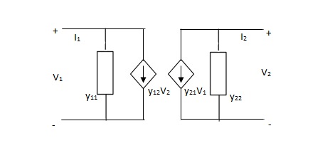
Y-parameter:-
I1 = Y11V1 + Y12V2
I2 = Y21V1 + Y22V2

Y11 =  V2=0
V2=0
Y12 =  V1=0
V1=0
Y21 =  V2=0
V2=0
Y22 =  V1=0
V1=0
V1& V2 should be independent
Equivalent circuit: -
Symmetrical two port N/W: -
 I2 = 0 =
  I1=0
I1=0
Y12 = Y22
Reciprocal two port N/W: -
 I1=0 =
 I2 = 0
Y12 = Y21
Que 1.
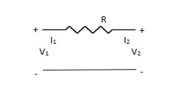

Solution: V1 – I1R – V2 = 0
V1 – V2 = I1R
I1 =  V1 -
V1 -  V2
V2
V2 = I2R + V1
I2 = -  V1 +
V1 +  V2
V2
Y11 = 
Y12 = Y21 = 
Y22 = 
Que 2.
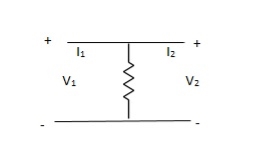
Solution: Y-parameter does not exist as V1 = V2
Que 3.
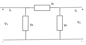
Solution: I1 = V1Ya + (V1 – V2)Yc
I1 = (Ya + Yc)V1 - YcV2
I2 = V2Yb + (V2 – V1)Yc
I1 = (Yb + Yc)V2 - YcV1
Y11 = Yb + Yc
Y12 = Y21 = - Yc
Y22 = Yb + Yc
Que 4.
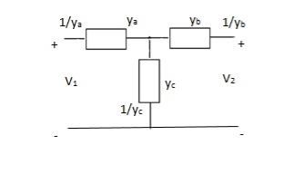
Solution:
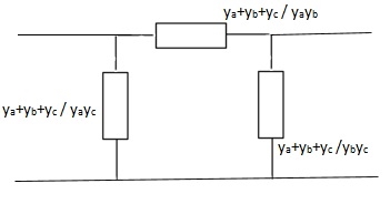
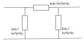

Que 5:
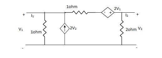
Find Y-parameter?
Solution:
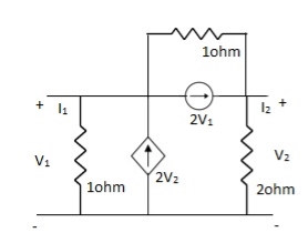
-I1 +  – 2V2 +
  + 2V1 = 0
I1= V1 + V1 - 3V2 + 2V1
I1= 4V1 - 3V2V
V2 + 2V2- 2V1 = 2(I2 + 2V1)
- 2V1 + 3V2 = 2(I2 + 2V1)
3V2 - 2V1 – 4V1 = 2I2
I2 = -3V1 +  V2
V2
Y11 = 4
Y12 = -3
Y21 = -3
Y22 = 
Transmission parameter [ABCD]
V1 = AV2 - BI2
I1 = CV2 - DI2

A =  I2=0
I2=0
B =  V2=0
V2=0
C =  -I2=0
-I2=0
D =  V2=0
V2=0
Symmetrical two port N/W :-
 I2 = 0 =
  I1=0
I1=0
A = D
Reciprocal two port N/W :-
 I1=0 =
 I2 = 0
AD – BC = 1
Que 1.
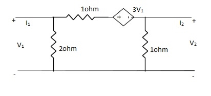
Solution:
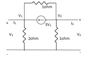
-3V1 – I1 +  +
+  = 0
= 0
 +
+  = I1
= I1
 V1 – V2 = I1
 V1 = V2 + I1
V1= V2-
V2-  I1----------------(1)
I2 = 3V1 + V2 + V2 – V1
I2 = 2V1 + 2V2
2V1 = I2 - 2V2
2V1 = - 2V2 + I2
V1 = -V2 +  I2 ----------------(2)
A = -1
B = 
From (1) & (2)
-V2 +  I2 =
I2 =  I1 -
I1 -  V2
V2
 V2 - V2 +
  I2 =
I2 =  I1
I1
 I1 =
I1 =  V2 + V2 -
  I2
I2
I1 =  V2 -
V2 -  I2
I2
C = 
D = 
Que 2.
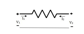
Solution: V1 = RI1 + V2 ----------------(1)
I2R = V2 – V1
I2 =  V2 -
V2 -  V1
V1
I2R = V2 – V1
V1 = I2R - V2 --------------------(2)
A = 1
B = R
From (2) in (1)
V2 - I2R = V2 + RI1
I2 = -I1
C = 0
D = 1
Que 3.
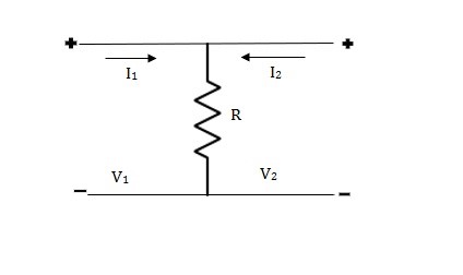
Solution: V1 = R(I1 + I2)
V2 = R(I1 + I2)
V1 = V2 + 0I2
A = 1
B = 0
V2 = RI1 + RI2
RI1= V2 - RI2
I1 =  V2 – I2
C =  , D = 1
H-parameter:
V1 = h11I1 + h12V2
I2 = h21I1 + h22V2
Equivalent circuit for H-parameter:
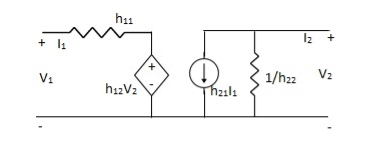
Fig: Equivalent circuit for H-parameter
h11 =  V2=0
V2=0
h12 =  I1=0
I1=0
h21 =  V2=0
V2=0
h22 =  I1=0
I1=0
Symmetrical two port N/W: -
 I2 = 0 =
  I1=0
I1=0
∆h = 0
Reciprocal two port N/W: -
 I1=0 =
 I2 = 0
h12 = h21
Que. Find all h-parameter?
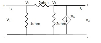
Solution: +
+  = I1
= I1
 V1 -
V1 -  = I1
= I1
 V1 =
V1 =  + I1
+ I1
V1 = +
+  I1
I1
-  + 3I1 = I2
3I1 + V2 = I2
= I2
From (1)
I2 = 3I1 + V2 –  [
[ I1 +
I1 +  V2]
V2]
I2 =  I1 +
I1 +  V2
V2
h11 = 
h12 = 
h21 = 
h22 = 
Key takeaway
Relationship of two-port variables
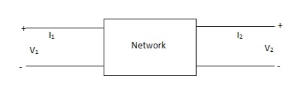
Fig: 2 Port network

Fig: 1 port network
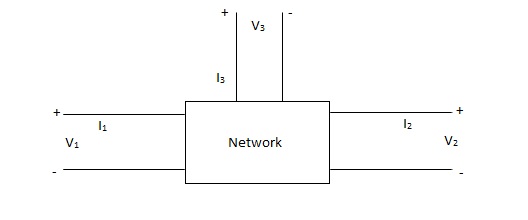
Fig: 3 port network
z-parameter  open circuit impedance
y-parameter  short circuit admittance
h-parameter  hybrid parameter
g-parameter  inverse hybrid parameter
ABCD-parameter  transmission parameter
A’B’C’D’ parameter  inverse transmission
s-parameter  scattering
Used for very high frequency application
Relationship of Two Part Variables
Condition for Reciprocity and Symmetry
Sr No. | Parameter | Reciprocity | Symmetry |
1. | Z Parameter | Z12 = Z21 | Z11= Z22 |
2. | Y Parameter | Y12 = Y21 | Y12 = Y21 |
3. | h Parameter | h12 = h21 | Δ = 1 |
4. | ABCD Parameter | AD-BC = 1 | A = D |
5. | Inverse h Parameter | g12 = g21 | Δ = 1 |
6. | Inverse Transmission | A1D1 – B1 C1= 1 | A1 = D1 |
Series connection
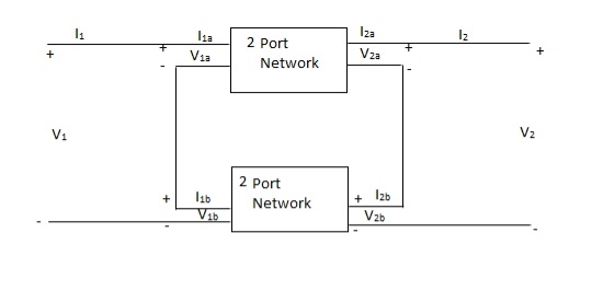
V1 = V1a +V1b
I1 = I1a = I1b
V2 = V2a +V2b
I2 = I2a = I2b
 =
= 
 =
= 
 =
= 
Parallel connection
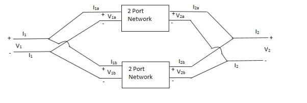
V1 = V1a = V1b
 =
= 
 =
= 
 =
= 
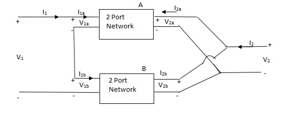
Series parallel connection
I1 = I1a = I1b
V1 = V1a +V1b
If two 2-ports are connected in series parallel then overall h-parameter is sum of individual h-parameter
 =
= 
Parallel series connection
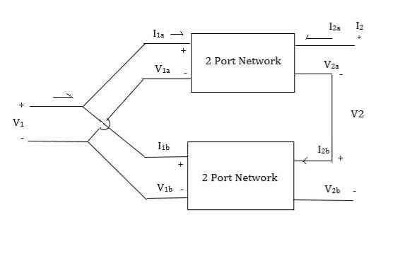
 =
= 
Cascade connection

V1 = V1a , V2a = V1b , V2 = V2b
I1 = I1a , I2a = -I1b , I2 = I2b
Transmission parameter for N/W (A)

Transmission parameter for N/W (B)

Overall transmission parameter

Que 1.
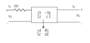
Find out overall transmission parameter?
Solution:
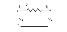


Que 2.
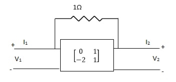
Find overall Y-parameter?
Solution:


Key takeaway
Relation between Two- Port Parameters:
Δ = X11 X22 – X12 X21 , ΔT = AD – BC
| [z] | [y] | [h] | [T] |
[z] | Z11 Z12 | y22 – y12  
| Δh – h12   | A – ΔT   |
Z21 Z22 | y21 – y11  
| -h21 h  
| 1 D   | |
|
|
|
|
|
[y] | Z22 -Z12  
| y11 y12 | 1 -h12  
| D – ΔT   |
-Z21 Z11   | y21 y22 | h21 Δn   | -1 A  
| |
|
|
|
|
|
[h] | Δz Z12  
| 1 -y12  
| h11 h12 | B ΔT   |
-Z21 -1   | y21 Δy   | H21 h22 | -1 C  
| |
[T] | Z21 ΔZ   | -y22 -1   | -Δh -h11  
| A B |
1 Z22  
| -Δy -y11  
| -h22 -1   | C D |
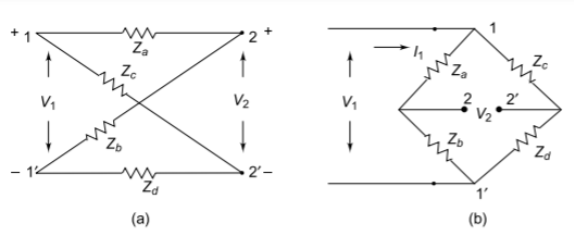
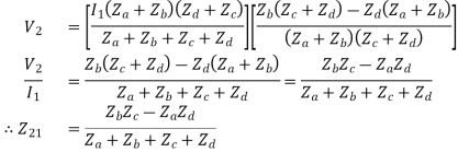
One of the common four-terminal two-port network is the lattice, or bridge network shown in Figure. Lattice networks are used in filter sections and are also used as attenuaters. Lattice structures are sometimes used in preference to ladder structures in some special applications. Za and Zd are called series arms, Zb and Zc are called the diagonal arms. It can be observed that, if Zd is zero, the lattice structure becomes a p-section. The lattice network is redrawn as a bridge network as shown in Figure.
Z11 =  I2=0
I2=0
When 

If the network is symmetric, then  and
and 


When  is the voltage across

Substituting the value of  from Eq, we have
If the network is symmetric, 

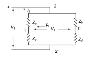
When the input port is open, 

The network can be redrawn as shown in Fig.


Substituting the value of  in Eq, we get


If the network is symmetric, 
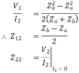
We have

If the network is symmetric,

From the above equations, 
And

Q) Obtain the lattice equivalent of a symmetrical T network figure?
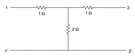
A) A two-port network can be realised as a symmetric lattice if it is reciprocal and symmetric. The z parameter of the network.
Z11= 3
Z12=Z21= 2 
Z22=3 
Since, Z11=Z22
Z12=Z21
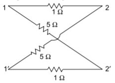
The given network is symmetrical and reciprocal. The parameters of the lattice network are
Za=Z11-Z12=1 
Zb=Z11+Z12=5 
The lattice network is shown below
Q) Obtain the lattice equivalent of a symmetric p-network shown in Figure?
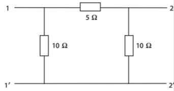
A) The Z parameters of the given network are
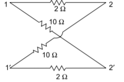
Z11=6  =Z22
=Z22
Z12=Z21=4 
Hence, the parameters of the lattice network are
Za=Z11-Z12=2 
Zb=Z11+Z12= 10 
For this type of network series are represented as impedance and about cum represent admittance.
Now we can find the transfer function of above network KCL and KVL and then substituting the value in each equation the equation is reached which relative the output to input
Z= 
Here, first Y6 is converted as Z6(=1 / Y6) Then combined with Z5 and this is called continued function method.
T-Networks
The circuit for T network is shown below
The z and y parameters of such networks are
Z1+Z3 = z11=  I2=0
I2=0
Z3=z12 =  I1=0
I1=0
Z3=z21 =  I2=0
I2=0
Z2+Z3=z22 =  I1=0
I1=0
As we see z12=z21 T network is always a reciprocal network
The y-parameters can be found as
 z= z11z22-z12z21
y11= z22/ z = Y1(Y2+Y3)/Y1+Y2+Y3
y22= z11/ z = Y2(Y1+Y3)/Y1+Y2+Y3
y12=y21= -z12/ z = -Y1Y2/Y1+Y2+Y3
Delta or π Network
A general π network is shown below. The y and z parameters can be found by short circuiting output and input ports respectively.
Ya+ Yb =y11 =  V2=0
V2=0
-Yb=y12 =  V1=0
V1=0
-Yb=y21 =  V2=0
V2=0
Yb+ Yc=y22 =  V1=0
V1=0
Since, y12=y21 the z parameters for the π network can be found by taking
Za=1/Ya
Zb=1/Yb
Zc=1/Yc
 y= y11y22-y12y21
z11=y22/ y= Za (Zb +Zc)/Za +Zb +Zc
z22=y11/ y= Zc (Zb +Za)/Za +Zb +Zc
z12=z21=-y12/ y= Za Zc/Za +Zb +Zc
References:
- Engineering Circuit Analysis”, by W H Hayt, TMH Eighth Edition
- “Network analysis and synthesis”, by F F Kuo, John Weily and Sons, 2nd Edition.
- “Circuit Theory”, by S Salivahanan, Vikas Publishing House 1st Edition, 2014
- “Network analysis”, by M. E. Van Valkenburg, PHI, 2000
- “Networks and Systems”, by D. R. Choudhary, New Age International, 1999
- Electric Circuit”, Bell Oxford Publications, 7th Edition.