Unit - 1
Binary Codes and Boolean algebra
Analog | Digital |
An analog signal is a continuous signal that represents physical measurements. | Digital signals are time separated signals which are generated using digital modulation. |
It is denoted by sine waves | It is denoted by square waves |
It uses a continuous range of values that help you to represent information. | Digital signal uses discrete 0 and 1 to represent information. |
Temperature sensors, FM radio signals, Photocells, Light sensor, Resistive touch screen are examples of Analog signals. | Computers, CDs, DVDs are some examples of Digital signal. |
The analog signal bandwidth is low | The digital signal bandwidth is high. |
Analog signals are deteriorated by noise throughout transmission as well as write/read cycle. | Relatively a noise-immune system without deterioration during the transmission process and write/read cycle. |
Analog hardware never offers flexible implementation. | Digital hardware offers flexibility in implementation. |
It is suited for audio and video transmission. | It is suited for Computing and digital electronics. |
Processing can be done in real-time and consumes lesser bandwidth compared to a digital signal. | It never gives a guarantee that digital signal processing can be performed in real time. |
Analog instruments usually have s scale which is cramped at lower end and gives considerable observational errors. | Digital instruments never cause any kind of observational errors. |
Analog signal doesn't offer any fixed range. | Digital signal has a finite number, i.e., 0 and 1. |
Binary Number System
- It uses two digits 0 and 1.
- It is also called as base 2 number system.
- Here, each position in any binary number represents a power of the base (2). Example: 23
- The last position represents a y power of the base (2). Example: 2y where y represents the last position.
Example
Binary Number: 101112
Calculating the Decimal Equivalent of binary number −
Step | Binary Number | Decimal Number |
Step 1 | 101012 | ((1 × 24) + (0 × 23) + (1 × 22) + (1 × 21) + (1 × 20))10 |
Step 2 | 101012 | (16 + 0 + 4 + 2 + 1)10 |
Step 3 | 101012 | 2310 |
Note: 101112 is normally written as 10111.
Binary Addition
- It is a basis for binary subtraction, multiplication, division.
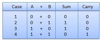
- There are four rules which are as follows:
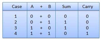
Rules of Binary addition
In fourth step, a sum (1 + 1 = 10) i.e. 0 is written in the given column and a carry of 1 over to the next column is done.
For Example −

Binary addition
Binary Subtraction
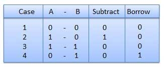
Subtraction and Borrow, these are the two words that will be used very frequently for binary subtraction. There rules of binary subtraction are:
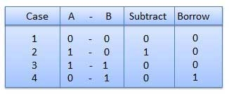
Rules of Binary Subtraction
For Example

Fig. Binary subtraction
Binary Multiplication
- It is similar to decimal multiplication.
- It is also simpler than decimal multiplication as only 0s and 1s are involved.
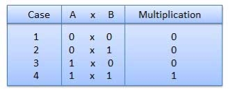
- There are four rules of binary multiplication which are:
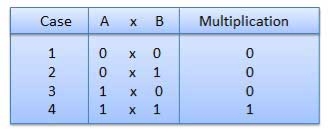
Rules of Binary Multiplication
For Example
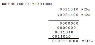
Fig. Binary Multiplication
Binary Division
- It is similar to decimal division.
- It is also called as the long division procedure.
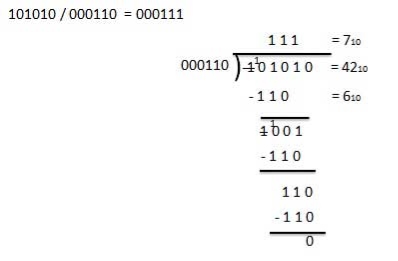
For Example
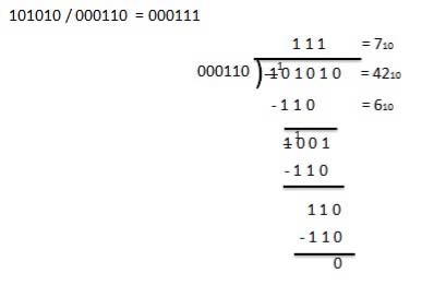
Binary Division
- In the first step, find the 2's complement of the subtrahend.
- Add the complement number with the minuend.
- If we get the carry by adding both the numbers, then we discard this carry and the result is positive else take 2's complement of the result which will be negative.
Example 1: 10101 - 00111
We take 2's complement of subtrahend 00111, which is 11001. Now, sum them. So,
10101+11001 =1 01110.
In the above result, we get the carry bit 1. So we discard this carry bit and remaining is the final result and a positive number.
Example 2: 10101 – 10111
We take 2's complement of subtrahend 10111, which comes out 01001. Now, we add both of the numbers. So,
10101+01001 =11110.
In the above result, we didn't get the carry bit. So calculate the 2's complement of the result, i.e., 00010. It is the negative number and the final answer.
- In coding, when alpha-numeric characters or words are represented by a specific group of symbols, it is said that it is being coded.
- The group of symbols is known as a code.
- The digital data can be represented, stored and transmitted as group of binary bits.
- This group is called as binary code.
- It is represented by the number as well as alphanumeric character.
Advantages of Binary Code
- They are used in computer applications.
- They are suitable for digital communications.
- They make the analysis and designing of digital circuits easy.
- Implementation becomes very easy since only 0 & 1 are being used.
Classification of binary codes
The codes are broadly classified as:
- Weighted Codes
- Non-Weighted Codes
- Binary Coded Decimal Code
- Alphanumeric Codes
- Error Detecting Codes
- Error Correcting Codes
Weighted Codes
- These codes obey the positional weight principle.
- Here each position represents a specific weight.
- Several systems are used to express the decimal digits 0 through 9.
- Here, each decimal digit is represented by a set of four bits.
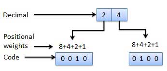
Fig.: Weighted codes
Non-Weighted Codes
- Here, the positional weights are not assigned.
- Example: Excess-3 code and Gray code.
Self-complementing binary codes are those whose members complement on themselves. For a binary code to become a self-complementing code, the following two conditions must be satisfied:
1. The complement of a binary number should be obtained from that number by replacing 1’s with 0’s and 0’s with 1’s (already stated procedure).
2. The sum of the binary number and its complement should be equal to decimal 9.
Binary Coded Decimal (BCD) code
- Here each decimal digit is represented by a 4-bit binary number.
- Its a way to express each of the decimal digits with a binary code.
- Therefore, by four bits we can represent sixteen numbers (0000 to 1111).
- But in BCD code only first ten of these numbers are used (0000 to 1001) and rest are invalid.

Fig.: BCD codes
Advantages of BCD Codes
- It is very similar to decimal system.
- We have to remember binary equivalent of 0 to 9 only.
Disadvantages of BCD Codes
- The addition and subtraction of BCD number system have different rules.
- The BCD arithmetic is more complicated.
- BCD code requires more number of bits than binary code to represent the decimal number.
- Hence is less efficient than binary.
- It is also known as XS-3 code.
- It is a non-weighted code used to express decimal numbers.
- They are derived from the 8421 BCD code words adding (0011)2 or (3)10 to each code word in 8421.
- The excess-3 codes are obtained as −

Example
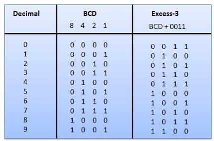
Fig.: BCD to XS 3 conversion
- It is the non-weighted code and is not an arithmetic code.
- This means that there are no specific weights assigned to the bit position.
- Here only one bit will change every time the decimal number is incremented.
- The gray code is also known as a unit distance code as only one-bit changes at a time.
- The gray code is a type of cyclic code.
- It cannot be used for all arithmetic operation.
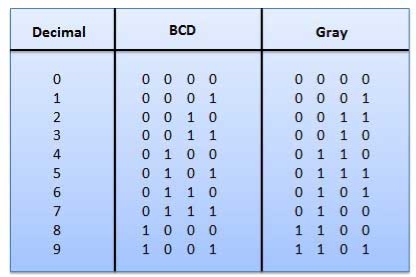
Fig: Gray codes
Application of Gray code
- They are used in the shaft position encoders.
- This encoder produces a code word which represents the angular position of the shaft.
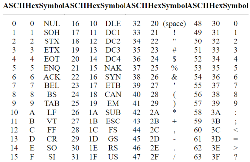
A binary digit orbit can be represented by two symbols as '0' or '1'.
This is not sufficient for communication between two computers as we need many more symbols for communication.
These symbols represent 26 alphabetic characters with capital and small letters, numbers from 0 to 9, punctuation marks, and other symbols.
These alphanumeric codes represent numbers and alphabetic characters.
Most of them also represent other characters like symbols and various instructions necessary for conveying information.
The code at least represents 10 digits and 26 letters of alphabet i.e., total of 36 items.
The following three types of alphanumeric codes are commonly used for data representation.
- American Standard Code for Information Interchange (ASCII).
- Extended Binary Coded Decimal Interchange Code (EBCDIC).
- Five bit Baudot Code.
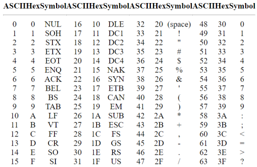
ASCII code is a 7-bit code whereas EBCDIC is an 8-bit code.
ASCII code is used worldwide while EBCDIC is primarily used in large IBM computers.
Boolean Algebra is used to analyze and simplify the digital (logic) circuits. It uses only the binary numbers i.e. 0 and 1. It is also called as Binary Algebra or logical Algebra. Boolean algebra was invented by George Boole in 1854.
Rule in Boolean Algebra
Following are the important rules used in Boolean algebra.
- Variable used can have only two values. Binary 1 for HIGH and Binary 0 for LOW.
- Complement of a variable is represented by an overbar (-). Thus, complement of variable B is represented as
 . Thus if B = 0 then
  = 1 and B = 1 then
  = 0.
= 0. - ORing of the variables is represented by a plus (+) sign between them. For example ORing of A, B, C is represented as A + B + C.
- Logical ANDing of the two or more variable is represented by writing a dot between them such as A.B.C. Sometime the dot may be omitted like ABC.
Boolean Laws
- It deals with binary numbers & variables.
- Therefore, also known as Binary Algebra or logical Algebra.
- A mathematician named as George Boole had developed this algebra in 1854.
- The variables that are used in this algebra are known as Boolean variables.
- Considering the range of voltages as logic ‘High’ is represented with ‘1’ and logic ‘Low’ is represented with ‘0’.
Postulates and Basic Laws of Boolean Algebra
Here, the Boolean postulates and basic laws that are used are given underneath.
Boolean Postulates
- Considering the binary numbers 0 and 1, boolean variable (x) and its complement (x’).
- They known as literal.
- The possible logical OR operations are:
x + 0 = x
x + 1 = 1
x + x = x
x + x’ = 1
- Similarly, the possible logical AND operations are:
x.1 = x
x.0 = 0
x.x = x
x.x’ = 0
- These are the simple Boolean postulates and verification can be done by substituting the Boolean variable with ‘0’ or ‘1’.
Basic Laws of Boolean Algebra
The three basic laws of Boolean Algebra are:
- Commutative law
- Associative law
- Distributive law
Commutative Law
- The logical operation carried between two Boolean variables when gives the same result irrespective of the order the two variables, then that operation is said to be Commutative. The logical OR & logical AND operations between x & y are shown below
x + y = y + x
x.y = y.x
- The symbol ‘+’ and ‘.’ indicates logical OR operation and logical AND operation.
- Commutative law holds good for logical OR & logical AND operations.
Associative Law
- If a logical OR operation of any two Boolean variables is performed first and then the same operation is performed with the remaining variable providing the same result, then that operation is said to be Associative. The logical OR & logical AND operations of x, y & z are:
x + (y + z) = (x + y) + z
x.(y.z) = (x.y).z
- Associative law holds good for logical OR & logical AND operations.
Distributive Law
- If a logical OR operation of any two Boolean variables is performed first and then AND operation is performed with the remaining variable, then that logical operation is said to be Distributive. The distribution of logical OR & logical AND operations between variables x, y & z are :
x.(y + z) = x.y + x.z
x + (y.z) = (x + y).(x + z)
- Distributive law holds good for logical OR and logical AND operations.
- These are the Basic laws of Boolean algebra and we can verify them by substituting the Boolean variables with ‘0’ or ‘1’.
Logic Gates
The basic gates are namely AND gate, OR gate & NOT gate.
AND gate
It is a digital circuit that consists of two or more inputs and a single output which is the logical AND of all those inputs. It is represented with the symbol ‘.’.
The following is the truth table of 2-input AND gate.
A | B | Y = A. B |
0 | 0 | 0 |
0 | 1 | 0 |
1 | 0 | 0 |
1 | 1 | 1 |
Here A, B are the inputs and Y is the output of two input AND gate.
If both inputs are ‘1’, then only the output, Y is ‘1’. For remaining combinations of inputs, the output, Y is ‘0’.
The figure below shows the symbol of an AND gate, which is having two inputs A, B and one output, Y.

Fig: AND gate
OR gate
It is a digital circuit which has two or more inputs and a single output which is the logical OR of all those inputs. It is represented with the symbol ‘+’.
The truth table of 2-input OR gate is:
A | B | Y = A + B |
0 | 0 | 0 |
0 | 1 | 1 |
1 | 0 | 1 |
1 | 1 | 1 |
Here A, B are the inputs and Y is the output of two input OR gate.
When both inputs are ‘0’, then only the output, Y is ‘0’. For remaining combinations of inputs, the output, Y is ‘1’.
The figure below shows the symbol of an OR gate, which is having two inputs A, B and one output, Y.

Fig: OR gate
NOT gate
It is a digital circuit that has one input and one output. Here the output is the logical inversion of input. Hence, it is also called as an inverter.
The truth table of NOT gate is:
A | Y = A’ |
0 | 1 |
1 | 0 |
Here A and Y are the corresponding input and output of NOT gate. When A is ‘0’, then, Y is ‘1’. Similarly, when, A is ‘1’, then, Y is ‘0’.
The figure below shows the symbol of NOT gate, which has one input, A and one output, Y.

Fig: NOT gate
Special Gates
Ex-OR gate
It stands for Exclusive-OR gate. Its function varies when the inputs have even number of ones.
The truth table of 2-input Ex-OR gate is:
A | B | Y = A⊕B |
0 | 0 | 0 |
0 | 1 | 1 |
1 | 0 | 1 |
1 | 1 | 0 |
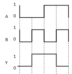
Here A, B are the inputs and Y is the output of two input Ex-OR gate. The output (Y) is zero instead of one when both the inputs are one.
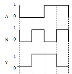
Therefore, the output of Ex-OR gate is ‘1’, when only one of the two inputs is ‘1’. And it is zero, when both inputs are same.
The symbol of Ex-OR gate is as follows:

Fig.: XOR gate
It is similar to that of OR gate with an exception for few combination(s) of inputs. Hence, the output is also known as an odd function.
Timing Diagram:
Ex-NOR gate
It stands for Exclusive-NOR gate. Its function is same as that of NOR gate except when the inputs having even number of ones.
The truth table of 2-input Ex-NOR gate is:
A | B | Y = A⊙B |
0 | 0 | 1 |
0 | 1 | 0 |
1 | 0 | 0 |
1 | 1 | 1 |
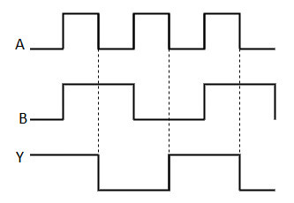
Here A, B are the inputs and Y is the output. It is same as Ex-NOR gate with the only modification in the fourth row. The output is 1 instead of 0, when both the inputs are one.
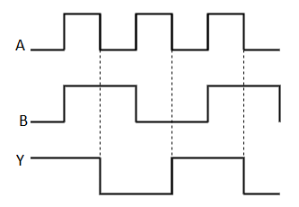
Hence the output of Ex-NOR gate is ‘1’, when both inputs are same and 0, when both the inputs are different.
The symbol of Ex-NOR gate is:

Fig.: XNOR gate
It is similar to NOR gate except for few combination(s) of inputs. Here the output is ‘1’, when even number of 1 is present at the inputs. Hence is also called as an even function.
Timing Diagram:
Universal gates
- NAND & NOR gates are known as universal gates.
- We can implement any Boolean function by using NAND gates and NOR gates alone.
NAND gate
It is a digital circuit which has two or more inputs and single output and it is the inversion of logical AND gate.
The truth table of 2-input NAND gate is:
A | B | Y = (A.B)’ |
0 | 0 | 1 |
0 | 1 | 1 |
1 | 0 | 1 |
1 | 1 | 0 |
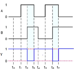
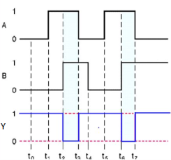
Here A, B are the inputs and Y is the output of two input NAND gate. When both inputs are ‘1’, then the output, Y is ‘0’. If at least one of the input is zero, then the output, Y is ‘1’. This is just the inverse of AND operation.
The image shows the symbol of NAND gate:

Fig.: NAND gate
NAND gate works same as AND gate followed by an inverter.
Timing Diagram:
NOR gate
It is a digital circuit that has two or more inputs and a single output which is the inversion of logical OR of all inputs.
The truth table of 2-input NOR gate is:
A | B | Y = (A+B)’ |
0 | 0 | 1 |
0 | 1 | 0 |
1 | 0 | 0 |
1 | 1 | 0 |
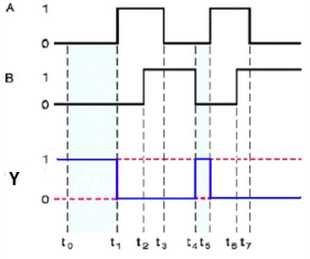
Here A and B are the two inputs and Y is the output. If both inputs are ‘0’, then the output is ‘1’. If any one of the input is ‘1’, then the output is ‘0’. This is exactly opposite to two input OR gate operation.
The symbol of NOR gate is:

Fig.: NOR gate
NOR gate works exactly same as that of OR gate followed by an inverter.
Timing Diagram:
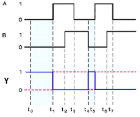
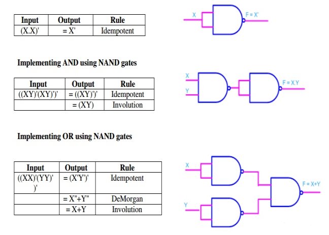
- Any logic function can be implemented using NAND gates.
- For this, the logic function has to be written in Sum of Product (SOP) form.
Consider the following SOP expression F = W.X.Y + X.Y.Z + Y.Z.W
The above expression can be implemented with three AND gates in first stage and one OR gate in second stage as shown in figure.
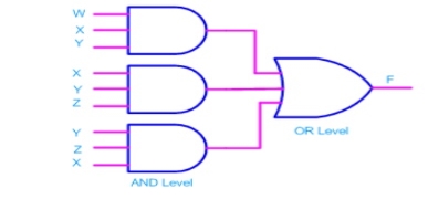
- If bubbles are introduced at AND gates output and OR gates input (the same for NOR gates), the above circuit becomes.
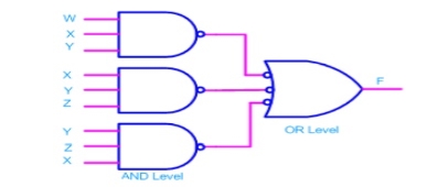
- Now replacing OR gate with input bubble with the NAND gate we have
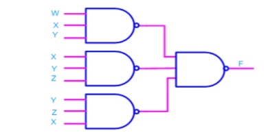
Realization of logic gates using NAND gates
Implementing an inverter using NAND gate

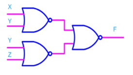
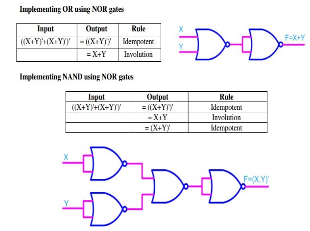
Realization of logic function using NOR gates
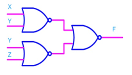
- Any logic function can be implemented using NOR gates.
- For this, the logic function has to be written in Product of Sum (POS) form
Consider the following POS expression F = (X+Y). (Y+Z)
- It can be implemented with three OR gates in first stage and one AND gate in second stage.

- If bubbles are introduced at the output of the OR gates and the inputs of AND gate, the above circuit comes out to be the next figure.
- Now replacing AND gate with input bubble with the NOR gate and we have circuit which is completely implemented with just NOR gates.
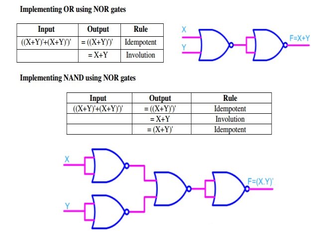
Implementing logic gates using NOR gate
- It is useful in finding the complement of Boolean function.
- It states that “The complement of logical OR of at least two Boolean variables is equal to the logical AND of each complemented variable”.
- It can be represented using 2 Boolean variables x and y as
(x + y)’ = x’.y’
- The dual of the above Boolean function is
(x.y)’ = x’ + y’
- Therefore, the complement of logical AND of the two Boolean variables is equivalent to the logical OR of each complemented variable.
- Similarly, DeMorgan’s theorem can be applied for more than 2 Boolean variables also.
- It states that “The dual of the Boolean function is obtained by interchanging the logical AND operator with logical OR operator and zeros with ones”.
- For every Boolean function, there is a Dual function.
- Let us make the Boolean equations (relations) of Boolean postulates and basic laws into two groups. The following table shows these two groups.
Group1 | Group2 |
x + 0 = x | x.1 = x |
x + 1 = 1 | x.0 = 0 |
x + x = x | x.x = x |
x + x’ = 1 | x.x’ = 0 |
x + y = y + x | x.y = y.x |
x + (y + z) = (x + y) + z | x.(y.z) = (x.y).z |
x.(y + z) = x.y + x.z | x + (y.z) = (x + y).(x + z) |
- Every row comprise of two Boolean equations and they are dual to one other.
- We can also verify the Boolean equations of Group1 and 2 by using duality theorem.
References:
1. Rajkamal ‘Digital Systems Principals and Design’ Pearson Education
2. A.P. Malvino, D.P. Leach ‘Digital Principles & Applicatios’ -VIth Edition-TMH publication.
3. M. Morris Mano ‘Digital Design’ (Third Edition). PHI Publications
Unit - 1
Binary Codes and Boolean algebra
Analog | Digital |
An analog signal is a continuous signal that represents physical measurements. | Digital signals are time separated signals which are generated using digital modulation. |
It is denoted by sine waves | It is denoted by square waves |
It uses a continuous range of values that help you to represent information. | Digital signal uses discrete 0 and 1 to represent information. |
Temperature sensors, FM radio signals, Photocells, Light sensor, Resistive touch screen are examples of Analog signals. | Computers, CDs, DVDs are some examples of Digital signal. |
The analog signal bandwidth is low | The digital signal bandwidth is high. |
Analog signals are deteriorated by noise throughout transmission as well as write/read cycle. | Relatively a noise-immune system without deterioration during the transmission process and write/read cycle. |
Analog hardware never offers flexible implementation. | Digital hardware offers flexibility in implementation. |
It is suited for audio and video transmission. | It is suited for Computing and digital electronics. |
Processing can be done in real-time and consumes lesser bandwidth compared to a digital signal. | It never gives a guarantee that digital signal processing can be performed in real time. |
Analog instruments usually have s scale which is cramped at lower end and gives considerable observational errors. | Digital instruments never cause any kind of observational errors. |
Analog signal doesn't offer any fixed range. | Digital signal has a finite number, i.e., 0 and 1. |
Binary Number System
- It uses two digits 0 and 1.
- It is also called as base 2 number system.
- Here, each position in any binary number represents a power of the base (2). Example: 23
- The last position represents a y power of the base (2). Example: 2y where y represents the last position.
Example
Binary Number: 101112
Calculating the Decimal Equivalent of binary number −
Step | Binary Number | Decimal Number |
Step 1 | 101012 | ((1 × 24) + (0 × 23) + (1 × 22) + (1 × 21) + (1 × 20))10 |
Step 2 | 101012 | (16 + 0 + 4 + 2 + 1)10 |
Step 3 | 101012 | 2310 |
Note: 101112 is normally written as 10111.
Binary Addition
- It is a basis for binary subtraction, multiplication, division.
- There are four rules which are as follows:
Rules of Binary addition
In fourth step, a sum (1 + 1 = 10) i.e. 0 is written in the given column and a carry of 1 over to the next column is done.
For Example −

Binary addition
Binary Subtraction
Subtraction and Borrow, these are the two words that will be used very frequently for binary subtraction. There rules of binary subtraction are:
Rules of Binary Subtraction
For Example

Fig. Binary subtraction
Binary Multiplication
- It is similar to decimal multiplication.
- It is also simpler than decimal multiplication as only 0s and 1s are involved.
- There are four rules of binary multiplication which are:
Rules of Binary Multiplication
For Example
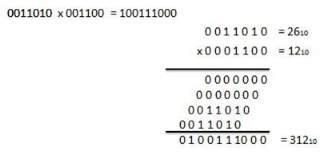
Fig. Binary Multiplication
Binary Division
- It is similar to decimal division.
- It is also called as the long division procedure.
For Example
Binary Division
- In the first step, find the 2's complement of the subtrahend.
- Add the complement number with the minuend.
- If we get the carry by adding both the numbers, then we discard this carry and the result is positive else take 2's complement of the result which will be negative.
Example 1: 10101 - 00111
We take 2's complement of subtrahend 00111, which is 11001. Now, sum them. So,
10101+11001 =1 01110.
In the above result, we get the carry bit 1. So we discard this carry bit and remaining is the final result and a positive number.
Example 2: 10101 – 10111
We take 2's complement of subtrahend 10111, which comes out 01001. Now, we add both of the numbers. So,
10101+01001 =11110.
In the above result, we didn't get the carry bit. So calculate the 2's complement of the result, i.e., 00010. It is the negative number and the final answer.
- In coding, when alpha-numeric characters or words are represented by a specific group of symbols, it is said that it is being coded.
- The group of symbols is known as a code.
- The digital data can be represented, stored and transmitted as group of binary bits.
- This group is called as binary code.
- It is represented by the number as well as alphanumeric character.
Advantages of Binary Code
- They are used in computer applications.
- They are suitable for digital communications.
- They make the analysis and designing of digital circuits easy.
- Implementation becomes very easy since only 0 & 1 are being used.
Classification of binary codes
The codes are broadly classified as:
- Weighted Codes
- Non-Weighted Codes
- Binary Coded Decimal Code
- Alphanumeric Codes
- Error Detecting Codes
- Error Correcting Codes
Weighted Codes
- These codes obey the positional weight principle.
- Here each position represents a specific weight.
- Several systems are used to express the decimal digits 0 through 9.
- Here, each decimal digit is represented by a set of four bits.
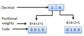
Fig.: Weighted codes
Non-Weighted Codes
- Here, the positional weights are not assigned.
- Example: Excess-3 code and Gray code.
Self-complementing binary codes are those whose members complement on themselves. For a binary code to become a self-complementing code, the following two conditions must be satisfied:
1. The complement of a binary number should be obtained from that number by replacing 1’s with 0’s and 0’s with 1’s (already stated procedure).
2. The sum of the binary number and its complement should be equal to decimal 9.
Binary Coded Decimal (BCD) code
- Here each decimal digit is represented by a 4-bit binary number.
- Its a way to express each of the decimal digits with a binary code.
- Therefore, by four bits we can represent sixteen numbers (0000 to 1111).
- But in BCD code only first ten of these numbers are used (0000 to 1001) and rest are invalid.

Fig.: BCD codes
Advantages of BCD Codes
- It is very similar to decimal system.
- We have to remember binary equivalent of 0 to 9 only.
Disadvantages of BCD Codes
- The addition and subtraction of BCD number system have different rules.
- The BCD arithmetic is more complicated.
- BCD code requires more number of bits than binary code to represent the decimal number.
- Hence is less efficient than binary.
- It is also known as XS-3 code.
- It is a non-weighted code used to express decimal numbers.
- They are derived from the 8421 BCD code words adding (0011)2 or (3)10 to each code word in 8421.
- The excess-3 codes are obtained as −

Example
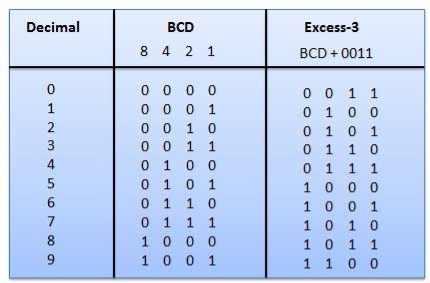
Fig.: BCD to XS 3 conversion
- It is the non-weighted code and is not an arithmetic code.
- This means that there are no specific weights assigned to the bit position.
- Here only one bit will change every time the decimal number is incremented.
- The gray code is also known as a unit distance code as only one-bit changes at a time.
- The gray code is a type of cyclic code.
- It cannot be used for all arithmetic operation.
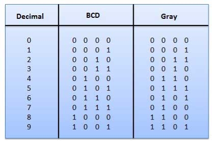
Fig: Gray codes
Application of Gray code
- They are used in the shaft position encoders.
- This encoder produces a code word which represents the angular position of the shaft.
A binary digit orbit can be represented by two symbols as '0' or '1'.
This is not sufficient for communication between two computers as we need many more symbols for communication.
These symbols represent 26 alphabetic characters with capital and small letters, numbers from 0 to 9, punctuation marks, and other symbols.
These alphanumeric codes represent numbers and alphabetic characters.
Most of them also represent other characters like symbols and various instructions necessary for conveying information.
The code at least represents 10 digits and 26 letters of alphabet i.e., total of 36 items.
The following three types of alphanumeric codes are commonly used for data representation.
- American Standard Code for Information Interchange (ASCII).
- Extended Binary Coded Decimal Interchange Code (EBCDIC).
- Five bit Baudot Code.
ASCII code is a 7-bit code whereas EBCDIC is an 8-bit code.
ASCII code is used worldwide while EBCDIC is primarily used in large IBM computers.
Boolean Algebra is used to analyze and simplify the digital (logic) circuits. It uses only the binary numbers i.e. 0 and 1. It is also called as Binary Algebra or logical Algebra. Boolean algebra was invented by George Boole in 1854.
Rule in Boolean Algebra
Following are the important rules used in Boolean algebra.
- Variable used can have only two values. Binary 1 for HIGH and Binary 0 for LOW.
- Complement of a variable is represented by an overbar (-). Thus, complement of variable B is represented as
 . Thus if B = 0 then
  = 1 and B = 1 then
  = 0.
= 0. - ORing of the variables is represented by a plus (+) sign between them. For example ORing of A, B, C is represented as A + B + C.
- Logical ANDing of the two or more variable is represented by writing a dot between them such as A.B.C. Sometime the dot may be omitted like ABC.
Boolean Laws
- It deals with binary numbers & variables.
- Therefore, also known as Binary Algebra or logical Algebra.
- A mathematician named as George Boole had developed this algebra in 1854.
- The variables that are used in this algebra are known as Boolean variables.
- Considering the range of voltages as logic ‘High’ is represented with ‘1’ and logic ‘Low’ is represented with ‘0’.
Postulates and Basic Laws of Boolean Algebra
Here, the Boolean postulates and basic laws that are used are given underneath.
Boolean Postulates
- Considering the binary numbers 0 and 1, boolean variable (x) and its complement (x’).
- They known as literal.
- The possible logical OR operations are:
x + 0 = x
x + 1 = 1
x + x = x
x + x’ = 1
- Similarly, the possible logical AND operations are:
x.1 = x
x.0 = 0
x.x = x
x.x’ = 0
- These are the simple Boolean postulates and verification can be done by substituting the Boolean variable with ‘0’ or ‘1’.
Basic Laws of Boolean Algebra
The three basic laws of Boolean Algebra are:
- Commutative law
- Associative law
- Distributive law
Commutative Law
- The logical operation carried between two Boolean variables when gives the same result irrespective of the order the two variables, then that operation is said to be Commutative. The logical OR & logical AND operations between x & y are shown below
x + y = y + x
x.y = y.x
- The symbol ‘+’ and ‘.’ indicates logical OR operation and logical AND operation.
- Commutative law holds good for logical OR & logical AND operations.
Associative Law
- If a logical OR operation of any two Boolean variables is performed first and then the same operation is performed with the remaining variable providing the same result, then that operation is said to be Associative. The logical OR & logical AND operations of x, y & z are:
x + (y + z) = (x + y) + z
x.(y.z) = (x.y).z
- Associative law holds good for logical OR & logical AND operations.
Distributive Law
- If a logical OR operation of any two Boolean variables is performed first and then AND operation is performed with the remaining variable, then that logical operation is said to be Distributive. The distribution of logical OR & logical AND operations between variables x, y & z are :
x.(y + z) = x.y + x.z
x + (y.z) = (x + y).(x + z)
- Distributive law holds good for logical OR and logical AND operations.
- These are the Basic laws of Boolean algebra and we can verify them by substituting the Boolean variables with ‘0’ or ‘1’.
Logic Gates
The basic gates are namely AND gate, OR gate & NOT gate.
AND gate
It is a digital circuit that consists of two or more inputs and a single output which is the logical AND of all those inputs. It is represented with the symbol ‘.’.
The following is the truth table of 2-input AND gate.
A | B | Y = A. B |
0 | 0 | 0 |
0 | 1 | 0 |
1 | 0 | 0 |
1 | 1 | 1 |
Here A, B are the inputs and Y is the output of two input AND gate.
If both inputs are ‘1’, then only the output, Y is ‘1’. For remaining combinations of inputs, the output, Y is ‘0’.
The figure below shows the symbol of an AND gate, which is having two inputs A, B and one output, Y.

Fig: AND gate
OR gate
It is a digital circuit which has two or more inputs and a single output which is the logical OR of all those inputs. It is represented with the symbol ‘+’.
The truth table of 2-input OR gate is:
A | B | Y = A + B |
0 | 0 | 0 |
0 | 1 | 1 |
1 | 0 | 1 |
1 | 1 | 1 |
Here A, B are the inputs and Y is the output of two input OR gate.
When both inputs are ‘0’, then only the output, Y is ‘0’. For remaining combinations of inputs, the output, Y is ‘1’.
The figure below shows the symbol of an OR gate, which is having two inputs A, B and one output, Y.

Fig: OR gate
NOT gate
It is a digital circuit that has one input and one output. Here the output is the logical inversion of input. Hence, it is also called as an inverter.
The truth table of NOT gate is:
A | Y = A’ |
0 | 1 |
1 | 0 |
Here A and Y are the corresponding input and output of NOT gate. When A is ‘0’, then, Y is ‘1’. Similarly, when, A is ‘1’, then, Y is ‘0’.
The figure below shows the symbol of NOT gate, which has one input, A and one output, Y.

Fig: NOT gate
Special Gates
Ex-OR gate
It stands for Exclusive-OR gate. Its function varies when the inputs have even number of ones.
The truth table of 2-input Ex-OR gate is:
A | B | Y = A⊕B |
0 | 0 | 0 |
0 | 1 | 1 |
1 | 0 | 1 |
1 | 1 | 0 |
Here A, B are the inputs and Y is the output of two input Ex-OR gate. The output (Y) is zero instead of one when both the inputs are one.
Therefore, the output of Ex-OR gate is ‘1’, when only one of the two inputs is ‘1’. And it is zero, when both inputs are same.
The symbol of Ex-OR gate is as follows:

Fig.: XOR gate
It is similar to that of OR gate with an exception for few combination(s) of inputs. Hence, the output is also known as an odd function.
Timing Diagram:
Ex-NOR gate
It stands for Exclusive-NOR gate. Its function is same as that of NOR gate except when the inputs having even number of ones.
The truth table of 2-input Ex-NOR gate is:
A | B | Y = A⊙B |
0 | 0 | 1 |
0 | 1 | 0 |
1 | 0 | 0 |
1 | 1 | 1 |
Here A, B are the inputs and Y is the output. It is same as Ex-NOR gate with the only modification in the fourth row. The output is 1 instead of 0, when both the inputs are one.
Hence the output of Ex-NOR gate is ‘1’, when both inputs are same and 0, when both the inputs are different.
The symbol of Ex-NOR gate is:

Fig.: XNOR gate
It is similar to NOR gate except for few combination(s) of inputs. Here the output is ‘1’, when even number of 1 is present at the inputs. Hence is also called as an even function.
Timing Diagram:
Universal gates
- NAND & NOR gates are known as universal gates.
- We can implement any Boolean function by using NAND gates and NOR gates alone.
NAND gate
It is a digital circuit which has two or more inputs and single output and it is the inversion of logical AND gate.
The truth table of 2-input NAND gate is:
A | B | Y = (A.B)’ |
0 | 0 | 1 |
0 | 1 | 1 |
1 | 0 | 1 |
1 | 1 | 0 |
Here A, B are the inputs and Y is the output of two input NAND gate. When both inputs are ‘1’, then the output, Y is ‘0’. If at least one of the input is zero, then the output, Y is ‘1’. This is just the inverse of AND operation.
The image shows the symbol of NAND gate:

Fig.: NAND gate
NAND gate works same as AND gate followed by an inverter.
Timing Diagram:
NOR gate
It is a digital circuit that has two or more inputs and a single output which is the inversion of logical OR of all inputs.
The truth table of 2-input NOR gate is:
A | B | Y = (A+B)’ |
0 | 0 | 1 |
0 | 1 | 0 |
1 | 0 | 0 |
1 | 1 | 0 |
Here A and B are the two inputs and Y is the output. If both inputs are ‘0’, then the output is ‘1’. If any one of the input is ‘1’, then the output is ‘0’. This is exactly opposite to two input OR gate operation.
The symbol of NOR gate is:

Fig.: NOR gate
NOR gate works exactly same as that of OR gate followed by an inverter.
Timing Diagram:
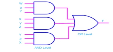
- Any logic function can be implemented using NAND gates.
- For this, the logic function has to be written in Sum of Product (SOP) form.
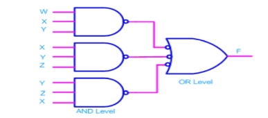
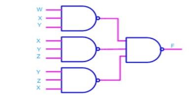
Consider the following SOP expression F = W.X.Y + X.Y.Z + Y.Z.W
The above expression can be implemented with three AND gates in first stage and one OR gate in second stage as shown in figure.
- If bubbles are introduced at AND gates output and OR gates input (the same for NOR gates), the above circuit becomes.
- Now replacing OR gate with input bubble with the NAND gate we have
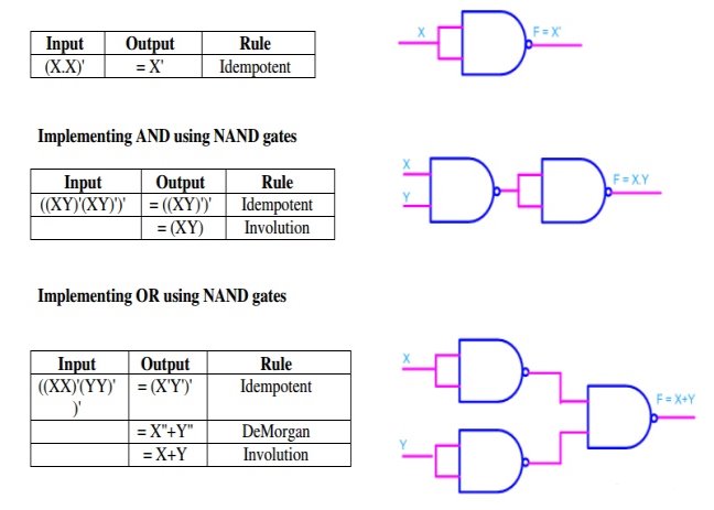
Realization of logic gates using NAND gates
Implementing an inverter using NAND gate

Realization of logic function using NOR gates
- Any logic function can be implemented using NOR gates.
- For this, the logic function has to be written in Product of Sum (POS) form
Consider the following POS expression F = (X+Y). (Y+Z)
- It can be implemented with three OR gates in first stage and one AND gate in second stage.

- If bubbles are introduced at the output of the OR gates and the inputs of AND gate, the above circuit comes out to be the next figure.
- Now replacing AND gate with input bubble with the NOR gate and we have circuit which is completely implemented with just NOR gates.
Implementing logic gates using NOR gate
- It is useful in finding the complement of Boolean function.
- It states that “The complement of logical OR of at least two Boolean variables is equal to the logical AND of each complemented variable”.
- It can be represented using 2 Boolean variables x and y as
(x + y)’ = x’.y’
- The dual of the above Boolean function is
(x.y)’ = x’ + y’
- Therefore, the complement of logical AND of the two Boolean variables is equivalent to the logical OR of each complemented variable.
- Similarly, DeMorgan’s theorem can be applied for more than 2 Boolean variables also.
- It states that “The dual of the Boolean function is obtained by interchanging the logical AND operator with logical OR operator and zeros with ones”.
- For every Boolean function, there is a Dual function.
- Let us make the Boolean equations (relations) of Boolean postulates and basic laws into two groups. The following table shows these two groups.
Group1 | Group2 |
x + 0 = x | x.1 = x |
x + 1 = 1 | x.0 = 0 |
x + x = x | x.x = x |
x + x’ = 1 | x.x’ = 0 |
x + y = y + x | x.y = y.x |
x + (y + z) = (x + y) + z | x.(y.z) = (x.y).z |
x.(y + z) = x.y + x.z | x + (y.z) = (x + y).(x + z) |
- Every row comprise of two Boolean equations and they are dual to one other.
- We can also verify the Boolean equations of Group1 and 2 by using duality theorem.
References:
1. Rajkamal ‘Digital Systems Principals and Design’ Pearson Education
2. A.P. Malvino, D.P. Leach ‘Digital Principles & Applicatios’ -VIth Edition-TMH publication.
3. M. Morris Mano ‘Digital Design’ (Third Edition). PHI Publications