Unit - 4
Instruction Set and Programming
Microcontroller 8051 has a 16-bit address bus for transferring data. It addresses memory locations to transfer address from CPU to Memory. It has four addressing modes that are:
- Immediate addressing modes.
- Bank address (or) Register addressing mode.
- Direct Addressing mode.
- Register indirect addressing mode.
8051 Instruction consists of an Opcode in short of Operation – Code followed by an operand(s) of size zero-byte, one byte or two bytes.
The Opcode contains the mnemonic, which specifies the type of operation to be performed.
All Mnemonics or the Opcode part of the instruction are of One Byte size.
In the operand part it defines the data being processed by the instructions.
The operand can be any of the following:
● No Operand
● Data value
● I/O Port
● Memory Location
● CPU register
There can multiple operands and the format of instruction is as follows:
MNEMONIC DESTINATION OPERAND, SOURCE OPERAND
Instruction can be one-byte instruction, which contains only opcode, or two-byte instructions, where the second byte is the operand or three byte instructions, where the operand makes up the second and third byte.
The 8051 microcontrollers have only one data type which is 8 bits and the size of each register is also 8 bits. It is the job of the programmer to break down data larger than 8 bits to be processed by the CPU.
The data types used by the 8051 can be positive or negative.
DB (define byte)
It is used to define the 8-bit data. When DB is used to define data, the numbers can be decimal, binary, hex, or ASCII formats.
For decimal, the “D” after the decimal number is optional but using “B” (binary) and “H” (hexadecimal) for the others is required.
● To indicate ASCII, simply place the characters in quotation marks .The assembler will assign the ASCII code for the numbers or characters automatically.
● The DB directive is the only directive that can be used to define ASCII strings larger than two characters; therefore, it should be used for all ASCII data definitions.
Following are some DB examples:
ORG 2000H
DATA1: DB 28; DECIMAL NUMBER 28
DATA2: DB 1234h; HEXADECIMAL
DATA3: DB "ABCD"; ASCII CHARACTER
A subroutine is a separate program or part of the main program that can be called to perform a specific function. The subroutine may be required by the main program or another subroutine as many times as necessary.
When you call a subroutine implementing the current program is stopped the program counter PC is loaded with the memory location of the subroutine running up to RET instruction where a return to the main program resumes running. The high level languages such as C, basic subroutines are known as functions or procedures.
ADDRESSING MODES
An Addressing Mode is a way to locate a target Data, which is also called as Operand.
They addressing modes are:
▪ Immediate addressing
▪ Register addressing
▪ Direct addressing
▪ Indirect addressing
▪ Relative addressing
▪ Indexed addressing
▪ Bit inherent addressing
▪ Bit direct addressing.
Immediate Addressing
In Immediate Addressing mode, the operand, which follows the Opcode, is a constant data of either 8 or 16 bits. The name Immediate Addressing came from the fact that the constant data to be stored in the memory immediately follows the Opcode.
The constant value to be stored is specified in the instruction itself rather than taking from a register. The destination register to which the constant data must be copied should be the same size as the operand mentioned in the instruction.
Example: MOV A, #030H
Here, the Accumulator is loaded with 30 (hexadecimal). The # in the operand indicates that it is a data and not the address of a Register.
Immediate Addressing is very fast as the data to be loaded is given in the instruction itself.
Register Addressing
In Register Addressing mode, one of the eight registers (R0 – R7) is specified as Operand in the Instruction.
Example: MOV A, R5
Here, the 8-bit content of the Register R5 of Bank0 is moved to the Accumulator.
Direct Addressing
In Direct Addressing Mode, the address of the data is specified as the Operand in the instruction.
Example: MOV A, 47H
Here, the data in the RAM location 47H is moved to the Accumulator.
Register Indirect Addressing
In Indirect Addressing Mode or Register Indirect Addressing Mode, the address of the Operand is specified as the content of a Register.
Example: MOV A, @R1
The @ symbol indicates that the addressing mode is indirect. If the contents of R1 is 56H, for example, then the operand is in the internal RAM location 56H. If the contents of the RAM location 56H is 24H, then 24H is moved into the accumulator.
Only R0 and R1 are allowed in Indirect Addressing Mode. These registers in the indirect addressing mode are called Pointer registers.
Indexed Addressing Mode
In Indexed Addressing Mode, the effective address of the Operand is the sum of a base register and an offset register.
The Base Register can be either a Data Pointer (DPTR) or Program Counter (PC) while the Offset register is the Accumulator (A).
In Indexed Addressing Mode, only MOVC and JMP instructions can be used. Indexed Addressing Mode is useful when retrieving data from look-up tables.
Example: MOVC A, @A+DPTR
Here, the address for the operand is the sum of contents of DPTR and Accumulator.
Bit Inherent Addressing
In this addressing, the address of the flag which contains the operand, is implied in the opcode of the instruction.
E.g. CLR C; Clears the carry flag to 0
Bit Direct Addressing
In this addressing mode the direct address of the bit is specified in the instruction. The RAM space 20H to 2FH and most of the special function registers are a bit addressable. Bit address values are between 00H to 7FH.
E.g. CLR 07h; Clears the bit 7 of 20h RAM space
SETB 07H; Sets the bit 7 of 20H RAM space
Relative addressing
It is a version of Displacement addressing mode.
In this the contents of the PC(Program Counter) is added to address part of instruction to obtain the effective address.
EA = A + (PC), where EA is an effective address and PC is a program counter.
The operand is A cells away from the current cell(the one pointed to by PC)
The instructions are classified into five different groups. These groups are like below
● Data Transfer Group
● Arithmetic Group
● Logical Group
● Program Branch Group
● Bit Processing Group
This Bit-Processing group is also known as Boolean Variable Manipulation.
In 8051 the internal operations and external read/write operations were controlled by the oscillator clock.
T-state, Machine cycle and Instruction cycle are terms used in instruction timings.
T-state is defined as one subdivision of the operation performed in one clock period. The terms 'T- state' and 'clock period' are often used synonymously.
A machine cycle consists of six states and each state lasts for two oscillator periods. An instruction takes one to four machine cycles to execute an instruction.
Instruction cycle is defined as the time required for completing the execution of an instruction. The instruction cycle consists of one to four machine cycles.
E.g. If an 8051 microcontroller is operated with a 12 MHz oscillator, find the execution time for the following four instructions.
1. ADD A, 45H
2. SUBB A, #55H
3. MOV DPTR, #2000H
4. MUL AB
Since the oscillator frequency is 12 MHz, the clock period is, Clock period = 1/12 MHz = 0.08333 µS. Time for 1 machine cycle = 0.08333 µS x 12 =1 µS.
S.NO. | Instruction | No. Of machine cycles | Execution time |
1 | ADD A, 45H | 1 | 1 µs |
2 | SUBB A, #55H | 2 | 2 µs |
3 | MOV DPTR, #2000H | 2 | 2 µs |
4 | MUL AB | 4 | 4 µs |
Instruction Set
The instructions of 8051 can be broadly classified as:
1. Data transfer instructions
2. Arithmetic instructions
3. Logical instructions
4. Branch instructions
5. Subroutine instructions
6. Bit manipulation instructions
MOV A,Rn - Moves the Rn register to the accumulator
The instruction moves the Rn register to the accumulator. The Rn register is not affected.
EXAMPLE:
0123 ……
0124 (Label) MOV A,R3
0125 ……….
Before execution: R3=58h
After execution: R3=58h A=58h
MOV A,@Ri - Moves indirect RAM to accumulator
Description: The instruction moves the indirectly addressed register of RAM to the accumulator. The register address is stored in the Ri register (R0 or R1). The result is stored in the accumulator.
EXAMPLE:
0123 …..
0124 (Label) MOV A,@Ro
0125 ……
Register Address SUM=F2h R0=F2h
Before execution: SUM=58h
After execution: A=58h SUM=58h
MOV A, direct - Moves the direct byte to the accumulator
Description: Instruction moves the direct byte to the accumulator. As it is direct addressing, the register can be any SFRs or general-purpose register with address 0-7Fh. (0-127 dec.). After executing the instruction, the register is not affected.
EXAMPLE:
0723 …..
0724 (Label ) MOV REG,A
0725
Before execution: A=98h
After execution: A=98h REG=98h
MOV direct,@Ri - Moves the indirect RAM to the direct byte
Description: Instruction moves the indirectly addressed register of RAM to the direct byte. The register is not affected.
EXAMPLE:
0123 …..
0124 (Label) MOV TEMP,@R1
0125 ……
Register Address SUM=F3
Before execution: SUM=58h R1=F3
After execution: SUM=58h TEMP=58h
MOV direct1, direct2 - Moves the direct byte to the direct byte
Description: Instruction moves the direct byte to another direct byte. As it is direct addressing, both registers can be any SFRs or general-purpose registers with address 0-7Fh. (0-127 dec.). The direct1 is not affected.
EXAMPLE:
0223 …..
0224 (Label) MOV SUM,TEMP
0225 ……
Before execution: TEMP=58h
After execution: TEMP=58h SUM=58h
MOV @Ri,A - Moves the accumulator to the indirect RAM
Description: Instruction moves the accumulator to the indirectly addressed register of RAM. The register address is stored in the Ri register (R0 or R1). After executing the instruction, the accumulator is not affected.
EXAMPLE:
0123 …..
0124 (Label) MOV @R0,A
0125 ……
Register Address SUM=F2h
Before execution: R0=F2h A=58h
After execution: SUM=58h A=58h
MOV direct, #data - Moves the immediate data to the direct byte
Description: Instruction moves the immediate data to the direct byte. As it is direct addressing, the direct byte can be any SFRs or general-purpose register with address 0-7Fh. (0-127 dec.).
EXAMPLE:
0123 …..
0124 (Label) MOV TEMP,#22
0125 ……
After execution: TEMP=22h
MOV @Ri,#data - Moves the immediate data to the indirect RAM
Description: Instruction moves the immediate data to the directly addressed register of RAM. The register address is stored in the Ri register (R0 or R1).
EXAMPLE:
0123 …..
0124 (Label) MOV @R1,#44
0125 ……
Register address TEMP=E2h
Before execution: R1=E2h
After execution: TEMP=44h
MOV @Ri, direct - Moves the direct byte to the indirect RAM
Description: Instruction moves the direct byte to a register the address of which is stored in the Ri register (R0 or R1). After executing the instruction, the direct byte is not affected.
EXAMPLE:
0123 …..
0124 (Label) MOV @R1,ZBIR
0125 ……
Register address TEMP=E2h
Before execution: SUM=58h R1=E2h
After execution: SUM=58h TEMP=58h
MOVC A, @A+DPTR - Moves the code byte relative to the DPTR to the accumulator
Description: Instruction first adds the 16-bit DPTR register to the accumulator. The result of addition is then used as a memory address from which the 8-bit data is moved to the accumulator.
EXAMPLE:
0100 MOVC A,@A+DPTR
----
1100 Table1a DB 66h
1101 DB 77h
1102 DB 88h
1103 DB 99h
Before execution:
DPTR=1000:
A=0
A=1
A=2
A=3
After execution:
A=66h
A=77h
A=88h
A=99h
MOV DPTR, #data16 - Loads the data pointer with a 16-bit constant
Description: Instruction stores a 16-bit constant to the DPTR register. The 8 high bits of the constant are stored in the DPH register, while the 8 low bits are stored in the DPL register.
EXAMPLE:
0123 …….
0124 (Labela) MOV DPTR, #1234
0125
After execution: DPH=12h DPL=34h
MOVX A,@Ri - Moves the external RAM (8-bit address) to the accumulator
Description: Instruction reads the content of a register in external RAM and moves it to the accumulator. The register address is stored in the Ri register (R0 or R1).
EXAMPLE:
0123 ……
0124 (Labela) MOVX A,@R0
0125
Register Address: SUM=12h
Before execution: SUM=58h R0=12h
After execution: A=58h
MOVC A,@A+PC - Moves the code byte relative to the PC to the accumulator
Description: Instruction first adds the 16-bit PC register to the accumulator (the current program address is stored in the PC register). The result of addition is then used as a memory address from which the 8-bit data is moved to the accumulator.
EXAMPLE:
0100 | (Tabela) INC A |
0101 | MOVC A,@A+PC |
0102 | RET |
0103 | DB 66h |
0104 | DB 77h |
0105 | DB 88h |
0106 | DB 99h |
After the subroutine "Table" has been executed, one of four values is stored in the accumulator:
Before execution:
A=0
A=1
A=2
A=3
After execution:
A=66h
A=77h
A=88h
A=99h
MOVX @Ri,A - Moves the accumulator to the external RAM (8-bit address)
Description: Instruction moves the accumulator to a register stored in external RAM. Its address is stored in the Ri register.
EXAMPLE:
0123 ……
0124 (Label) MOVX @R1,A
0125 ……
Register address: SUM=34h
Before execution: A=58 R1=34h
After execution: SUM=58h
MOVX A,@DPTR - Moves the external memory (16-bit address) to the accumulator
Description: Instruction moves the content of a register in external memory to the accumulator. The 16-bit address of the register is stored in the DPTR register (DPH and DPL).
EXAMPLE:
0123 ……
0124 (Label) MOVX @R1,A
0125 ……
Register address: SUM=1234h
Before execution: DPTR=1234h SUM=58
After execution: A=58h
MOVX @DPTR, A - Moves the accumulator to the external RAM (16-bit address)
Description: Instruction moves the accumulator to a register stored in external RAM. The 16-bit address of the register is stored in the DPTR register (DPH and DPL).
EXAMPLE:
0123 ……
0124 (Label) MOVX @DPTR,A
0125 ……
Register address: SUM=1234h
Before execution: A=58 DPTR=1234h
After execution: SUM=58h
The 8051 can perform addition, subtraction. Multiplication and division operations on 8 bit numbers.
Addition
In this group, we have instructions to
i. Add the contents of A with immediate data with or without carry.
i. ADD A, #45H
Ii. ADDC A, #OB4H
Ii. Add the contents of A with register Rn with or without carry.
i. ADD A, R5
Ii. ADDC A, R2
Iii. Add the contents of A with contents of memory with or without carry using direct and indirect addressing
i. ADD A, 51H
Ii. ADDC A, 75H
Iii. ADD A, @R1
Iv. ADDC A, @R0
CY AC and OV flags will be affected by this operation.
Subtraction
In this group, we have instructions to
i. Subtract the contents of A with immediate data with or without carry.
i. SUBB A, #45H
Ii. SUBB A, #OB4H
Ii. Subtract the contents of A with register Rn with or without carry.
i. SUBB A, R5
Ii. SUBB A, R2
Iii. Subtract the contents of A with contents of memory with or without carry using direct and indirect addressing
i. SUBB A, 51H
Ii. SUBB A, 75H
Iii. SUBB A, @R1
Iv. SUBB A, @R0
CY AC and OV flags will be affected by this operation.
Multiplication
MUL AB. This instruction multiplies two 8 bit unsigned numbers which are stored in A and B registers. After multiplication the lower byte of the result will be stored in the accumulator and higher byte of result will be stored in B register.
E.g. MOV A,#45H ;[A]=45H
MOV B,#0F5H ;[B]=F5H
MUL AB ;[A] x [B] = 45 x F5 = 4209
;[A]=09H, [B]=42H
Division
DIV AB. This instruction divides the 8 bit unsigned number which is stored in A by the 8 bit unsigned number which is stored in B register. After division the result will be stored in the accumulator and remainder will be stored in B register.
E.g. MOV A,#45H ;[A]=0E8H
MOV B,#0F5H ;[B]=1BH
DIV AB ;[A] / [B] = E8 /1B = 08 H with remainder 10H
;[A] = 08H, [B]=10H
DAA (Decimal Adjust After Addition).
When two BCD numbers are added, the answer is a non-BCD number. To get the result in BCD, we use DA A instruction after the addition. DA A works as follows.
• If lower nibble is greater than 9 or auxiliary carry is 1, 6 is added to lower nibble.
• If the upper nibble is greater than 9 or carry is 1, 6 is added to the upper nibble.
Eg 1: MOV A,#23H
MOV R1,#55H
ADD A,R1 // [A]=78
DA A // [A]=78 no changes in the accumulator after da a
Eg 2: MOV A,#53H
MOV R1,#58H
ADD A,R1 // [A]=ABh
DA A // [A]=11, C=1 . ANSWER IS 111. Accumulator data is changed after DA A
Increment: increments the operand by one.
INC A INC Rn INC DIRECT INC @RiINC DPTR
INC increments the value of source by 1. If the initial value of register is FFh, incrementing the value will cause it to reset to 0. The Carry Flag is not set when the value "rolls over" from 255 to 0.
In the case of "INC DPTR", the value two-byte unsigned integer value of DPTR is incremented. If the initial value of DPTR is FFFFh, incrementing the value will cause it to reset to 0.
Decrement: decrements the operand by one.
DEC A DEC Rn DEC DIRECT DEC @Ri
DEC decrements the value of source by 1. If the initial value is 0, decrementing the value will cause it to reset to FFh. The Carry Flag is not set when the value "rolls over" from 0 to FFh.
Logical AND
ANL destination, source: ANL does a bitwise "AND" operation between source and destination, leaving the resulting value in destination. The value in source is not affected. "AND" instruction logically AND the bits of source and destination.
ANL A,#DATA ANL A, Rn ANL A,DIRECT ANL A,@Ri
ANL DIRECT,A ANL DIRECT, #DATA
Logical OR
ORL destination, source: ORL does a bitwise "OR" operation between source and destination,
Leaving the resulting value in destination. The value in source is not affected. " OR " instruction logically OR the bits of source and destination.
ORL A,#DATA ORL A, Rn
ORL A,DIRECT ORL A,@Ri
ORL DIRECT,A ORL DIRECT, #DATA
Logical Ex-OR
XRL destination, source: XRL does a bitwise "EX-OR" operation between source and destination, leaving the resulting value in destination. The value in source is not affected. " XRL " instruction logically EX-OR the bits of source and destination.
XRL A,#DATA XRL A,Rn XRL A,DIRECT XRL A,@Ri
XRL DIRECT,A XRL DIRECT, #DATA
Logical NOT
CPL complements operand, leaving the result in operand. If operand is a single bit then the state of the bit will be reversed. If operand is the Accumulator then all the bits in the Accumulator will be reversed.
CPL A, CPL C, CPL bit address
SWAP A – Swap the upper nibble and lower nibble of A.
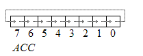
Rotate Instructions
RR A
This instruction is rotated right on the accumulator. Its operation is illustrated below. Each bit is shifted one
Location to the right, with bit 0 going to bit 7.
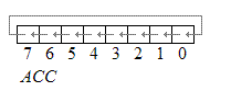
RL A
Rotate left the accumulator. Each bit is shifted one location to the left, with bit 7 going to bit 0
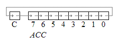
RRC A
Rotate right through the carry. Each bit is shifted one location to the right, with bit 0 going into the carry bit in the PSW, while the carry was at goes into bit 7
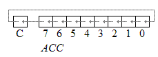
RLC A
Rotate left through the carry. Each bit is shifted one location to the left, with bit 7 going into the carry bit in the PSW, while the carry goes into bit 0.
Jump and Call Program Range
There are 3 types of jump instructions. They are:
1. Relative Jump
2. Short Absolute Jump
3. Long Absolute Jump
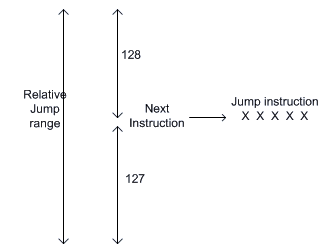
Relative Jump
Jump that replaces the PC (program counter) content with a new address that is greater than (the address following the jump instruction by 127 or less) or less than (the address following the jump by 128 or less) is called a relative jump. Schematically, the relative jump can be shown as follows: -
The advantages of the relative jump are as follows:
1. Only 1 byte of jump address needs to be specified in the 2's complement form, ie. For jumping ahead, the range is 0 to 127 and for jumping back, the range is -1 to -128.
2. Specifying only one byte reduces the size of the instruction and speeds up program execution.
3. The program with relative jumps can be relocated without reassembling to generate absolute jump addresses.
Disadvantages of the absolute jump: -
- Short jump range (-128 to 127 from the instruction following the jump instruction)
Instructions that use Relative Jump
SJMP <relative address>; this is unconditional jump
The remaining relative jumps are conditional jumps
JC <relative address> JNC <relative address> JB bit, <relative address>
JNB bit, <relative address> JBC bit, <relative address>
CJNE <destination byte>, <source byte>, <relative address> DJNZ <byte>, <relative address>
JZ <relative address> JNZ <relative address>
Short Absolute Jump
In this case only 11bits of the absolute jump address are needed. The absolute jump address is calculated in the following manner.
In 8051, 64 kbyte of program memory space is divided into 32 pages of 2 kbyte each. The hexadecimal addresses of the pages are given as follows:
Page (Hex) Address (Hex)
00 0000 - 07FF
01 0800 - 0FFF
02 1000 - 17FF
03 1800 - 1FFF
.
.
1E F000 - F7FF
1F F800 - FFFF
It can be seen that the upper 5bits of the program counter (PC) hold the page number and the lower 11bits of the PC hold the address within that page. Thus, an absolute address is formed by taking page numbers of the instruction (from the program counter) following the jump and attaching the specified 11bits to it to form the 16-bit address.
Advantage: The instruction length becomes 2 bytes. Example of short absolute jump: -
ACALL <address 11>
AJMP <address 11>
Long Absolute Jump/Call
Applications that need to access the entire program memory from 0000H to FFFFH use a long absolute jump. Since the absolute address has to be specified in the op-code, the instruction length is 3 bytes (except for JMP @ A+DPTR). This jump is not re-locatable.
Example: -
LCALL <address 16>
LJMP <address 16> JMP @A+DPTR
Another classification of jump instructions is
1. Unconditional Jump
2. Conditional Jump
1. The unconditional jump is a jump in which control is transferred unconditionally to the target location.
a. L JMP (long jump). This is a 3-byte instruction. First byte is the op-code and second and third bytes represent the 16-bit target address which is any memory location from 0000 to FFFFH
Eg: LJMP 3000H
b. AJMP: this causes unconditional branch to the indicated address, by loading the 11 bit address to 0 -10 bits of the program counter. The destination must be therefore within the same 2K blocks.
c. SJMP (short jump). This is a 2-byte instruction. First byte is the op-code and second byte is the relative target address, 00 to FFH (forward +127 and backward -128 bytes from the current PC value). To calculate the target address of a short jump, the second byte is added to the PC value which is the address of the instruction immediately below the jump.
2. Conditional Jump instructions.
JBC Jump if bit = 1 and clear bit
JNB Jump if bit = 0
JB Jump if bit = 1
JNC Jump if CY = 0
JC Jump if CY = 1
CJNE reg,#data Jump if byte ≠ #data
CJNE A,byte Jump if A ≠ byte
DJNZ Decrement and Jump if A ≠ 0
JNZ Jump if A ≠ 0
JZ Jump if A = 0
All conditional jumps are short jumps.
Bit level jump instructions:
Bit level JUMP instructions will check the conditions of the bit and if the condition is true, it jumps to the address specified in the instruction. All the bit jumps are relative jumps.
JB bit, rel ; jump if the direct bit is set to the relative address specified.
JNB bit, rel ; jump if the direct bit is clear to the relative address specified.
JBC bit, rel ; jump if the direct bit is set to the relative address specified and then clear the bit.
CALL And RETURN Instructions
Subroutines are handled by CALL and RET instructions There are two types of CALL instructions
1. LCALL address(16 bit)
This is long call instruction which unconditionally calls the subroutine located at the indicated 16 bit address. This is a 3 byte instruction. The LCALL instruction works as follows.
a. During execution of LCALL, [PC] = [PC]+3; (if address where LCALL resides is say, 0x3254; during execution of this instruction [PC] = 3254h + 3h = 3257h
b. [SP]=[SP]+1; (if SP contains default value 07, then SP increments and [SP]=08
c. [[SP]] = [PC7-0]; (lower byte of PC content ie., 57 will be stored in memory location 08.
d. [SP]=[SP]+1; (SP increments again and [SP]=09)
e. [[SP]] = [PC15-8]; (higher byte of PC content ie., 32 will be stored in memory location 09.
With these the address (0x3254) which was in the PC is stored in stack.
f. [PC]= address (16 bit); the new address of the subroutine is loaded to PC. No flags are affected.
2. ACALL address(11 bit)
This is absolute call instruction which unconditionally calls the subroutine located at the indicated 11 bit address. This is a 2 byte instruction. The SCALL instruction works as follows.
a. During execution of SCALL, [PC] = [PC]+2; (if address where LCALL resides is say, 0x8549; during execution of this instruction [PC] = 8549h + 2h = 854Bh
b. [SP]=[SP]+1; (if SP contains default value 07, then SP increments and [SP]=08
c. [[SP]] = [PC7-0]; (lower byte of PC content ie., 4B will be stored in memory location 08.
d. [SP]=[SP]+1; (SP increments again and [SP]=09)
e. [[SP]] = [PC15-8]; (higher byte of PC content ie., 85 will be stored in memory location 09.
With these the address (0x854B) which was in the PC is stored in stack.
f. [PC10-0]= address (11 bit); the new address of the subroutine is loaded to the PC. No flags are affected.
RET instruction
RET instruction pops top two contents from the stack and loads it to the PC.
g. [PC15-8] = [[SP]]; content of current top of the stack will be moved to a higher byte of PC.
h. [SP]=[SP]-1; (SP decrements)
i. [PC7-0] = [[SP]]; content of the bottom of the stack will be moved to the lower byte of the PC.
j. [SP]=[SP]-1; (SP decrements again)
8051 has 128 bit addressable memory. Bit addressable SFRs and bit addressable PORT pins. It is possible to perform following bit wise operations for these bit addressable locations.
1. LOGICAL AND
a. ANL C, BIT(BIT ADDRESS) ; ‘LOGICALLY AND’ CARRY AND CONTENT OF BIT ADDRESS, STORE RESULT IN CARRY
b. ANL C, /BIT; ; ‘LOGICALLY AND’ CARRY AND COMPLEMENT OF CONTENT OF BIT ADDRESS, STORE RESULT IN CARRY
2. LOGICAL OR
a. ORL C,BIT(BIT ADDRESS) ; ‘LOGICALLY OR’ CARRY AND CONTENT OF BIT ADDRESS, STORE RESULT IN CARRY
b. ORL C, /BIT; ; ‘LOGICALLY OR’ CARRY AND COMPLEMENT OF CONTENT OF BIT ADDRESS, STORE RESULT IN CARRY
3. CLR bit
a. CLR bit ; CONTENT OF BIT ADDRESS SPECIFIED WILL BE CLEARED.
b. CLR C ; CONTENT OF CARRY WILL BE CLEARED.
4. CPL bit
a. CPL bit ; CONTENT OF BIT ADDRESS SPECIFIED WILL BE COMPLEMENTED.
b. CPL C ; CONTENT OF CARRY WILL BE COMPLEMENTED.
The assembly language is made up of elements which all are used to write the program in a sequential manner.
Rules of Assembly Language
● The assembly code must be written in upper case letters
● The labels must be followed by a colon (label:)
● All symbols and labels must begin with a letter
● All comments are typed in lower case
● The last line of the program must be the END directive
The assembly language mnemonics are in the form of op-code, such as MOV, ADD, JMP, and so on, which are used to perform the operations.
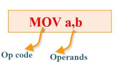
Op-code: The op-code is a single instruction that can be executed by the CPU. Here the op-code is a MOV instruction.
Operands: The operands are a single piece of data that can be operated by the op-code. Example, multiplication operation is performed by the operands that are multiplied by the operand.
Syntax: MUL a,b;
The Elements of an Assembly Language Programming:
● Assembler Directives
● Instruction Set
● Addressing Modes
Assembler Directives:
The assembling directives give the directions to the CPU. The most useful directives are 8051 programming, such as:
● ORG
● DB
● EQU
● END
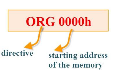
ORG(origin): This directive indicates the start of the program. This is used to set the register address during assembly.
For example; ORG 0000h tells the compiler all subsequent code starting at address 0000h.
Syntax: ORG 0000h
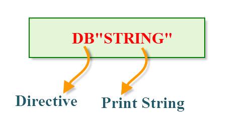
DB(define byte): The define byte is used to allow a string of bytes.
For example, print the “EDGEFX” wherein each character is taken by the address and finally prints the “string” by the DB directly with double quotes.
Syntax:
ORG 0000h
MOV a, #00h
————-
————-
DB”EDGEFX”
EQU (equivalent): The equivalent directive is used to equate address of the variable.
Syntax:
Reg equ,09h
—————–
—————–
MOV reg,#2h
END: The END directive is used to indicate the end of the program.
Syntax:
Reg equ,09h
—————–
—————–
MOV reg,#2h
END
Programs:
Addition:
ORG 0000h
MOV R0, #03H // move the value 3 to the register R0//
MOV A, #05H // move the value 5 to accumulator A//
Add A, 00H // addA value with R0 value and stores the result inA//
END
Multiplication:
ORG 0000h
MOV R0, #03H // move the value 3 to the register R0//
MOV A, #05H // move the value 5 to accumulator A//
MUL A, 03H // Multiplied result is stored in the Accumulator A //
END
Subtraction:
ORG 0000h
MOV R0, #03H // move the value 3 to register R0//
MOV A, #05H // move the value 5 to accumulator A//
SUBB A, 03H // Result value is stored in the Accumulator A //
END
Division:
ORG 0000h
MOV R0, #03H // move the value 3 to register R0//
MOV A, #15H // move the value 5 to accumulator A//
DIV A, 03H // final value is stored in the Accumulator A //
END
Program to copy data from R0 of Bank0 to R0 of Bank 3 copies the data from R0 of Bank0 to R0 of Bank3.
ORG 00H
MOV R0, #33H
MOV A, R0
SETB PSW.3
SETB PSW.4
MOV R0, A
END
Program to Toggle the LEDs ON and OFF (Blinking LEDs) that are connected to PORT1 of the 8051 Microcontroller.
ORG 00H ; Assembly Starts from 0000H.
; Main Program
START: MOV P1, #0XFF ; Move 11111111 to PORT1.
CALL WAIT ; Call WAIT
MOV A, P1 ; Move P1 value to ACC
CPL A ; Complement ACC
MOV P1, A ; Move ACC value to P1
CALL WAIT ; Call WAIT
SJMP START ; Jump to START
WAIT: MOV R2, #10 ; Load Register R2 with 10 (0x0A)
WAIT1: MOV R3, #200 ; Load Register R3 with 10 (0xC8)
WAIT2: MOV R4, #200 ; Load Register R4 with 10 (0xC8)
DJNZ R4, $ ; Decrement R4 till it is 0. Stay there if not 0.
DJNZ R3, WAIT2 ; Decrement R3 till it is 0. Jump to WAIT2 if not 0.
DJNZ R2, WAIT1 ; Decrement R2 till it is 0. Jump to WAIT1 if not 0.
RET ; Return to Main Program
END ; End Assembly
C language programs
Program to generate square wave using C
// Use Timer0 to create a 1kHz square
#include <REG52.H>
Sbit portbit = P1^0;
Void main()
{
TMOD = 1; // 16-bit mode on timer0
While (1) // Loop forever
{
TH0 = 0xFE; // Start timer at 2^16-500
TL0 = 0x0C;
TR0 = 1; // Start timer0
While (TF0 != 1); // Wait for overflow
TR0 = 0; // Stop timer
TF0 = 0; // Clear timer overflow flag
Portbit = !portbit; // Toggle port bit
}
}
Program to create delay:
#include <REG52.h>
Void delay(const unsigned int ms)
{
Unsigned int x;
For (x = 0; x < ms; x++)
{
Unsigned int y;
For (y = 0; y <= 113; y++);
}
}
Void main()
{
Unsigned char lights = 0xFF; P0 = lights;
While (1)
{
Delay(1000); lights = ~lights; P0 = lights;
}
}
The 8051 Assembler takes an assembly language source file created with a text editor and translates it into a machine language object file. This translation process is done in two passes over the source file.
During the first pass, the Cross Assembler builds a symbol table from the symbols and labels used in the source file.
During the second pass, the Cross Assembler actually translates the source file into the machine language object file. It is also during the second pass that the listing is generated.
Compiler:
▪ A compiler is a program which converts a high- level language program like “C” into binary or machine code.
▪ Using high level languages, it is easy to manage complex data structures which are often required for data manipulation.
▪ Because of its ease, flexibility and debug options compilers have become very popular in the market.
▪ Compilers like Keil, Ride and IAR workbench are very popular.
To develop an assembly language program, we require program development tools. An assembly language program consists of mnemonics that is instructions given to the controller. The various development tools required for Microcontroller programming are:
⮚ Editor:
It is a program which allows us to create a file to contain assembly language statements for the program. Examples of some editors are PC write Wordstar. When we type the program the editor stores ACSII codes for letters and numbers in successive RAM locations.
In case of any mistake like typing the wrong letter, the editor will alert us to correct it. After typing the program, we need to save it. This is called a source file. The next step is to process the source file with an assembler.
Ex: Sample. Asm
⮚ Assembler
▪ An Assembler translates assembly language mnemonics into machine language that is binary code.
▪ When you run the assembler, it reads the source file of your program from where you have saved it. It generates a file with extension. Hex. The file consists of hexadecimal values encoding a sequence of data and their starting offset or absolute address.
⮚ Compiler
▪ A compiler is a program which converts a high- level language program like “C” into binary or machine code.
▪ Using high level languages, it is easy to manage complex data structures which are often required for data manipulation.
▪ Because of its ease, flexibility and debug options compilers have become very popular in the market.
▪ Compilers like Keil, Ride and IAR workbench are very popular.
⮚ Debugger / Simulator
- A debugger is a program which allows you to execute the program, or debug it. The debugger debugs the contents of registers and memory locations after the program execution.
- It allows users to change the contents of registers and memory locations and rerun the program.
- Some debuggers allow the program to stop after each instruction to check or alter memory and register contents. This is called single step debug.
- A debugger sets a breakpoint at any point in the program.
- If we insert a break- point, the debugger will run the program up to the instruction where the breakpoint is put and then stop the execution.
- A simulator is a software program which virtually executes the instructions similar to microcontroller and shows the results.
- This will help in evaluating the results without committing any errors. By doing so we can detect the possible logic errors
Hardware Debugging tools:
- A logic analyzer is like an oscilloscope that is used to view multiple digital (binary) waveforms. It is used for precise hardware troubleshooting, especially for timing issues. It can be used for any type of digital circuit that has a binary output.
- We can set the threshold values for the logic highs and lows in the logic analyzer software.
It overcomes the limits of an oscilloscope by providing many channels of data, as well as long data display times.
- This is a 24 channel analyzer that can hold 128Kbytes of data in the buffer, and samples at rates upto 100M samples/sec .
- The output of a Logic Analyzer is usually in one of two forms. Time-domain display is commonly used where the binary waveforms from one or more digital sources is viewed as a function of time.
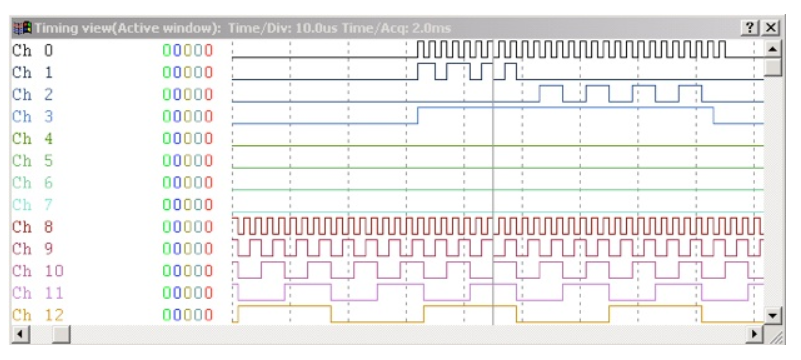
Timing Diagram in Logic Analyzer
References:
- 8051 Microcontroller: An Applications Based Introduction Book by David Calcutt, Frederick J. Cowan, and Hassan Parchizadeh
- 8051 Microcontrollers: Internals, Instructions, Programming, and Interfacing Book by Subrata Ghoshal
- C and the 8051: Building efficient applications Book by Thomas W. Schultz
- MICROCONTROLLER Book by V. Udayashankara
- The 8051/8052 Microcontroller: Architecture, Assembly Language, and Hardware Interfacing Book by Craig Steiner


