Unit - 5
Compensation design
Phase – Lead Compensation:
The phase of output voltage leads the phase of input voltage for the applied sinusoidal input. The circuit diagram is shown below. The transfer function is given as,
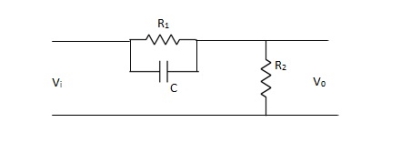
Fig. Phase Lead Compensation
Vo/Vi = α(1 + ST)/(1 + S α T)
Where, α = R2/R1 + R2 and α< 1
T = R1C
w = 1/T lower corner frequency due to zero.
w = 1/ αT upper corner frequency due to pole.
Mid frequency is given as,
wm = 1/T√ α
The maximum phase lead angle is φm
Φm = tan-1(1- α)/2√α = Sin-11- α/1 + α
Phase Lag Compensation:
The phase of the output voltage lags the phase of the input voltage for applied sinusoidal input. The circuit diagram is shown below,
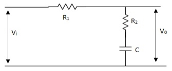
Fig. Phase Lag Compensation
Vo/Vi = 1 + ST/1 + SβT
Where, β = R1 + R2/R2, β> 1
T = R2C
w = 1/T upper corner frequency due to zero
w= 1/βT lower corner frequency due to pole
The mid frequency wm,
wm = 1/T√β
The maximum phase lead angle Φm
Φm = tan-11- β/2 √β
= sin-11 – β/1 + β
Phase Lag-Lead Network:
To overcome the disadvantages of lead and lag compensation, they are used together. As lead compensation does not provide phase margin but has fast response and lag compensation stabilize the system but does not provide enough bandwidth.
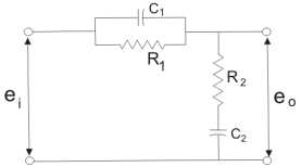
Fig. Lag-Lead Compensation
eo/ei = (1 + α ST1)/(1 + ST2)
Where, αT1 = R1C1
T2= R2C2
We can say in the lag-lead compensation pole is more dominating than the zero and because of this lag-lead network may introduces positive phase angle to the system when connected in series.
Key takeaway
Phase Lead Network | Phase Lag Network |
1>. It is used to improve the transient response | 1>It is used to improve the Steady state response.
|
2>. It acts as a high pass filter. | 2>It acts as a low pass filter. |
3>. The system becomes fast as Bandwidth increases as rise Time decreases. | 3>The Bandwidth decreases through rise time the speed is slow.
|
4>. As the circuit acts as differentiator, signal to noise ratio is poor.
| 4>Signal to noise ratio is higher as it acts as integrator. |
5>. Maximum peak overshoot is reduced. | 5>It reduces steady state error thus improve the steady state accuracy |
The compensator adds poles and zeros to the P(s) in the root locus procedure. Hence, we can change the shape of the root locus. If we can capture desirable performance in terms of positions of closed loop poles then compensator design problem reduces to changing the shape of the root locus so that these desired closed-loop pole positions appear on the root locus and finding the gain that places the closed-loop pole positions at their desired positions.
The point s0 is on the root locus of P(s) if 1+KP(s0) = 0
In first order compensator design

And


And K=KCKG.
Phase condition: s0 is on root locus if ∠P(s0) = 180◦ + l 360◦

Magnitude condition: If s0 satisfies phase condition, the gain that puts a closed-loop pole at s0 is K = 1/|P(s0)|

Root Locus design
Basic procedure
- Translate design specifications into desired positions of dominant poles
- Sketch root locus of uncompensated system to see if desired positions can be achieved
- If not, choose the positions of the pole and zero of the compensators. So that the desired positions lie on the root locus (phase criterion), if that is possible
- Evaluate the gain required to put the poles there (magnitude criterion)
- Evaluate the total system gain so that the steady-state error constants can be determined
- If the steady state error constants are not satisfactory, repeat This procedure enables relatively straightforward design of systems with specifications in terms of rise time, settling time, and overshoot; i.e., the transient response.
Examples
Q1) Consider the following system

Where

Performance requirements for the system:
Steady state: Kv =5
Transient response:
Phase margin > 40°
Gain margin > 10 dB.
A) Analysis of the system with Gc(s) = K
1) 
For K = 5, the closed-loop system is unstable
Design of a lag compensator

2) 
3) Phase margin of the system 5G(s) is -13°, the closed-loop system is unstable. From the Bode diagram of 5G(jω) we obtain that the additional required phase margin of 40° + 12° = 52° is obtained at ω=0.5 rad/sec. The new gain crossover frequency will be: ωc = 0.5 rad/sec.
4) Place the zero of lag compensator at ω=1/T=0.1rad/sec.
5) The magnitude of 5G(jω) at the new gain crossover frequency ωc =0.5 rad/sec is 20 dB. In order to have ωc as the new gain crossover frequency, the lag compensator must give an attenuation of -20db at ωc.
6) Therefore - 20log  = - 20 dB,
  =10.
=10.

And

The Bode diagram is
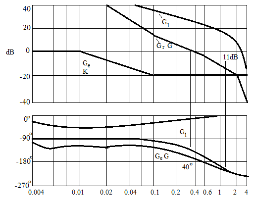
Bode diagrams for:
- G1(jω) = 5G(jω) (gain-adjusted KcβG(jω) open-loop transfer function)
- Gc(jω)/K = Gc(jω)/5 (compensator divided by gain Kcβ = 5)
- Gc(jω)G(jω) (compensated open-loop transfer function)
The effect of the lag compensator is:
- The original unstable closed-loop system is now stable.
- The phase margin 400 is acceptable transient response.
- The gain margin 11dB is acceptable transient response. Kv is 5 as required this is acceptable steady-state response.
- The gain at high frequencies has been decreased.
Q2) Given the control system
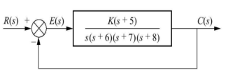
Find K such that there is a 10 percent error in steady state?
A2) Since system type is 1 the finite steady state error should be for a ramp input.
e(∞) = 1/ Kv = 0.1

We obtain K = 672
Q3) Consider the System (with one integrator) in the following figure

The steady state error for r(t) = 5u(t) will be?
A3) The steady state error for r(t) = 5u(t) will be

Q4) Consider the System (with one integrator) in the following figure

The steady state error for r(t) = 5tu(t) will be?
A4) The steady state error for r(t) = 5tu(t) will be

Q5) Consider the System (with one integrator) in the following figure

The steady state error for r(t) = 5t2u(t) will be?
A5) The steady state error for r(t) = 5t2u(t) will be

Q6) Consider the System (with no integrator) in the following figure

The steady state error for r(t) = 5u(t) will be?
A6) The steady state error for r(t) = 5u(t) is

Q7) Consider the System (with no integrator) in the following figure

The steady state error for r(t) = 5tu(t) will be?
A7) The steady state error for r(t) = 5tu(t) is

Q8) What is disturbance rejection in control system explain?
A8) Disturbances are unwanted signals entering into a feedback control system. A disturbance may act at the input or output of the plant. Here we consider the effect of input disturbance.
To characterize the effect of a disturbance input on the feedback control system, we consider the modified block diagram that includes a disturbance input.

Fig. Modified Block Diagram
Let r(t) denote a reference, and d(t) a disturbance input; then the system output is expressed in the Laplace domain as

Assuming unity-gain feedback configuration (H(s)=1) the tracking error, e(s), is computed as:

By using the Final Value Theorem, the steady-state error is expressed as:
 where Kp is the position error constant.
A large loop gain (large Kp) reduces steady-state error in the presence of both reference and disturbance inputs. A large controller gain, K, can be used to increase Kp, however, a large K would generate a large magnitude input signal to the plant, which may cause saturation in the actuator devices (amplifiers, mechanical actuators, etc.).
To analyze the control requirements for simultaneous tracking and disturbance rejection, we consider a unity-gain feedback control system (H(s)=1).
Let G(s)=n(s)d(s) represent the plant and K(s)=nC(s)dC(s) represent the controller; then, the output in the presence of reference and disturbance inputs is given as:

The characteristic polynomial is given as: Δ(s)=n(s)nc(s)+d(s)dc(s)
Asymptotic tracking. For asymptotic tracking, d(s)dc(s) should contain any unstable poles of r(s). For example, an integrator in the feedback loop ensures zero steady-state error to a constant reference input.
Disturbance Rejection. For disturbance rejection, n(s)dc(s) should contain any unstable poles of d(s). For example, a notch filter centered at 60 Hz removes power line noise from the measured signal
References:
1. I. J. Nagrath and M. Gopal, “Control Systems Engineering”, New Age International, 2009.
2. K. Ogata, “Modern Control Engineering”, Prentice Hall, 1991
3. M. Gopal, “Control Systems: Principles and Design”, McGraw Hill Education, 1997.
4. B. C. Kuo, “Automatic Control System”, Prentice Hall, 1995.