Unit - 4
Laplace and z- Transforms
Given a continuous-time signal x(t), the Laplace transform of x(t) is defined as
X(s) =  e -st dt -------------------------------------------------------(1)
X(s) is a function which takes complex numbers and returns complex number X(s) that is X(s) is function that maps the complex plane into the complex value.
The set of values of s for which the integral in (1) is well defined is called Region of Convergence.
Find the Laplace transform of e –t.
F(s) = 
F(s) = 
F(s) = 
F(s) = 1 / 1-s [ ]0
]0 
F (s = 1/ s-1.
Find the Laplace transform of unit -step function.
f(t) = 1 (t≥0)
F(s) =  -st dt = -1/s e -st | 0 ∞ = 1/s [ e -∞ - e -0] = 1
F(s) = 1/s.
Find the Laplace transform of e-at u(t)
X(s) =  at u(t) e -st dt =
  at e -st dt =
  –(s-a) t dt
= 1 – e –(s-a) ∞ / s-a
Key Takeaways:
This is the operator that transforms the signal in time domain in to a signal in a complex frequency domain called as ‘S’ domain. The complex frequency domain will be denoted by S and the complex frequency variable will be denoted by ‘s’
The response of an LTI system with impulse response h(t) to complex exponential input x(t) = e st is y(t) = H(s) e st where s ia complex number and
H(s) =  e -st dt
When s is purely imaginary this is Fourier transform H(jw)
When s is complex this is Laplace transform of h(t) , H(s )
Let z = r e jw and z n = r n e jwn
Then for input z n we get output H(z) z n

Figure 1. I/O relationship
Here H(z) is called the system function.
y[n] =  x[n-k]
= z n  z-k
z-k
Here z transform of h[k] is H[z].
Key Takeaways:
H(z) represents the Fourier transform
Consider the difference equation given by
 y[n-k] =
  x[n-k]
H(z) =  z -k /
  z -k
z -k
Poles : H(z) - ∞ ;  z -k = 0 , z=0 if bo=0.
Zeros : H(z) -> 0  z -k =0
In factored form
H(z) =  z -k /
  z -k = bo
  1 – ck z-1 ) / ao
  1 – dk z-1 )
Here bo 0 , ao
  0 .
0 .
Ck represents zeros denoted by “o”
Dk represents poles denoted by “x”
Example :
Find H(z), poles and zeros for the difference equation given by
y[n] – 3/8 y[n-1] – 7/16 y[n-2] = x[n] + x[n-2]
Solution:
Here ao=1,a1=-3/8,a2=-7/6,bo=1,b1=0,b2=1
H[z] = 1 + z -2 / 1 -3/8 z-1 -7/16 z -2
= (1+j z-1 ) (1 -jz-1) / (1-7/8 z-1) ( 1+1/2 z-1)
Zeros : z= j represented by o.
Poles z= 7/8 , z=-1/2 represented by x.
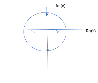
Figure 2. Poles and Zeros
Key Takeaways:
The poles of the system are indicated in the plot by an X while the zeros are indicated by a circle or O
Find io(t) using Laplace

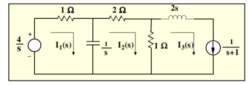
Figure 3. Mesh Network
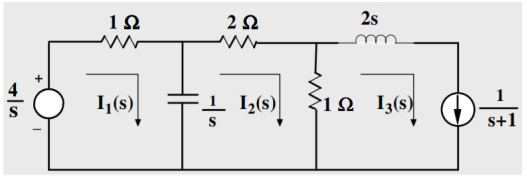
Figure 4. Laplace network
Mesh 1:
(s+1)/s I1(s) – I2(s)/s = 4/s
(s+1) I1(s) – I2(s) = 4
Mesh 2:
-1/s I1(s) + 3s+1/s I2(s) – I3(s) =0
-1/s I1(s) + 3s+1/s I2(s) – 1/s+1 =0
-I1(s) + (3s+1) I2(s) = s/s+1
-(s+1) I1(s) + (s+1)(3s+1) I2(s) = s
Adding these two equations we get
S(3s+4) I2(s) = s+4
I2(s) = (1/3) (s+4)/ s(s+4/3) = 1/s -2/3/ s+4/3
i2(t) = [ 1-2/3 e -4/3 t ] u(t)
-I1(s) + 3s+1/s . [1/s -2/3 /s+4/3] =s/s+1
-I1(s) = s/s+1 – 3s+1/s[ 1/s -2/3/s+4/3]
Key Takeaways:
Laplace techniques convert circuits with voltage and current signals that change with time to the s-domain so you can analyse the circuit's action using only algebraic techniques.
Using Laplce transform solve the differential equations :
y” – 3y’ -4y = -16x
y(0) = -4
y’(0) = -5
Apply the operator L to both sides of the differential equation; then use linearity, the initial conditions,
L[ y” – 3y’ -4y] = L[-16x]
L[ y”] – 3L[y’] -4L[y] = L[-16x]
[p 2 L[y] – p y’(0)] –[p L[y] – y[0]] – 4 L[y] = L[-16x]
p 2 L[y] +4p+5]-3[pL[y] +4] -4L[y] = -16/p2
(p2 -3p-4) L[y] + 4p -7 = -16/p2
L[y] = -16/p2 -4p +7/p2 – 3p -4
But the partial fraction decomposition of this expression for L[ y] is
-16/p2 -4p+7/ p2 -3p-4 = -16/p2 -4p+7/ p2 -3p-4 = -16-4p3+7p2/ p2(p+1)(p-4)
= -3/p + 4/p2 +1/p+1 +-2/p-4
Therefore,
y= L-1 [-3/p + 4/p2 + 1/p+1+-2/p-4]
Which yields
y=-3 +4x+e-x -2 e 4x
Key Takeaways:
The first step in using Laplace transforms to solve an IVP is to take the transform of every term in the differential equation
Given an analog signal x(t) the discrete time signal is represented by a sequence of weighted and delayed impulses.

Figure 5. Discrete time signal
A discrete time system is a mathematucal algorithm that takes an input sequence x[n] and produces output sequence y[n].
For any given sequence x[n] its z-transform is defined as :
X(z) =  z -n
z -n
= …….+x[-2] z2 + x[-1] z1 + x[0] zo + x[1] z -1 + x[2] z -2 +……..
Where z is complex variable.
Given xn=un that is step function input to the system
G(z) = 1/(1-0.9z-1) Then output yn is given by
Y(z) = G(z) X(z)
X(z) = z(un) = 1/1-z-1
Y(z) = G(z) . 1/1-z-1
Yn = z-1(G(z) / 1-z-1)
= z-1 ( 1/1-0.9 z-1 ). 1(1-z-1)
= 1/(1-0.9 z-1 )(1-z-1) = -0.9 / 1-0.9z-1 + 10/ 1-z-1
Yn = -9(0.9) n + 10
Poles are the values of z that make the denominator zero, and zeros are the values of z that make the numerator go to zero.
G(z) = 1/ 1+0.2 z-1 -0.48 z-2
= z 2/ z2 +0.2 z-0.48
= z2 / (z+0.8) (z-0.6)
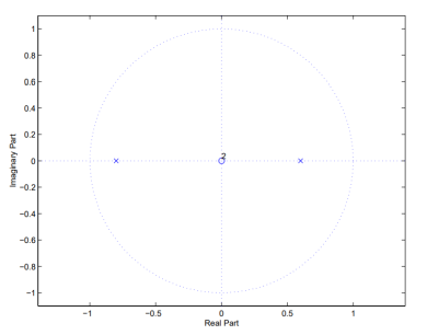
Figure 6. Poles and Zeros
Lets look at the system G(z)
G(z) = 1/1-az-1
The system has a pole at z=a and zero at z=0.
The impulse response of the system above is hn= an
Hence  =
=  a n |=
  n.
n.
For the system to be stable it must have finite sum. As  a n represents geometric expression te sum is finite if and only if |a|<1.
That means that the POLE must be within the unit circle!
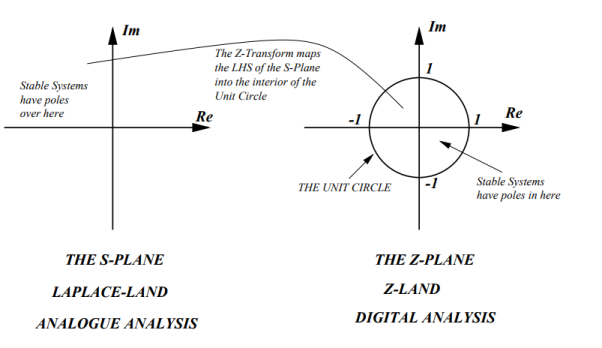
Figure 7. s-plane to z-plane
Key Takeaways:
The Z-transform converts a discrete-time signal, which is a sequence of real or complex numbers, into a complex frequency-domain representation.
References:
- Signals and Systems by Simon Haykin
- Signals and Systems by Ganesh Rao
- Signals and Systems by P. Ramesh Babu
- Signals and Systems by Chitode
Unit - 4
Laplace and z- Transforms
Given a continuous-time signal x(t), the Laplace transform of x(t) is defined as
X(s) =  e -st dt -------------------------------------------------------(1)
X(s) is a function which takes complex numbers and returns complex number X(s) that is X(s) is function that maps the complex plane into the complex value.
The set of values of s for which the integral in (1) is well defined is called Region of Convergence.
Find the Laplace transform of e –t.
F(s) = 
F(s) = 
F(s) = 
F(s) = 1 / 1-s [ ]0
]0 
F (s = 1/ s-1.
Find the Laplace transform of unit -step function.
f(t) = 1 (t≥0)
F(s) =  -st dt = -1/s e -st | 0 ∞ = 1/s [ e -∞ - e -0] = 1
F(s) = 1/s.
Find the Laplace transform of e-at u(t)
X(s) =  at u(t) e -st dt =
  at e -st dt =
  –(s-a) t dt
= 1 – e –(s-a) ∞ / s-a
Key Takeaways:
This is the operator that transforms the signal in time domain in to a signal in a complex frequency domain called as ‘S’ domain. The complex frequency domain will be denoted by S and the complex frequency variable will be denoted by ‘s’
The response of an LTI system with impulse response h(t) to complex exponential input x(t) = e st is y(t) = H(s) e st where s ia complex number and
H(s) =  e -st dt
When s is purely imaginary this is Fourier transform H(jw)
When s is complex this is Laplace transform of h(t) , H(s )
Let z = r e jw and z n = r n e jwn
Then for input z n we get output H(z) z n

Figure 1. I/O relationship
Here H(z) is called the system function.
y[n] =  x[n-k]
= z n  z-k
z-k
Here z transform of h[k] is H[z].
Key Takeaways:
H(z) represents the Fourier transform
Consider the difference equation given by
 y[n-k] =
  x[n-k]
H(z) =  z -k /
  z -k
z -k
Poles : H(z) - ∞ ;  z -k = 0 , z=0 if bo=0.
Zeros : H(z) -> 0  z -k =0
In factored form
H(z) =  z -k /
  z -k = bo
  1 – ck z-1 ) / ao
  1 – dk z-1 )
Here bo 0 , ao
  0 .
0 .
Ck represents zeros denoted by “o”
Dk represents poles denoted by “x”
Example :
Find H(z), poles and zeros for the difference equation given by
y[n] – 3/8 y[n-1] – 7/16 y[n-2] = x[n] + x[n-2]
Solution:
Here ao=1,a1=-3/8,a2=-7/6,bo=1,b1=0,b2=1
H[z] = 1 + z -2 / 1 -3/8 z-1 -7/16 z -2
= (1+j z-1 ) (1 -jz-1) / (1-7/8 z-1) ( 1+1/2 z-1)
Zeros : z= j represented by o.
Poles z= 7/8 , z=-1/2 represented by x.
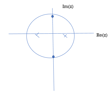
Figure 2. Poles and Zeros
Key Takeaways:
The poles of the system are indicated in the plot by an X while the zeros are indicated by a circle or O
Find io(t) using Laplace

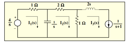
Figure 3. Mesh Network
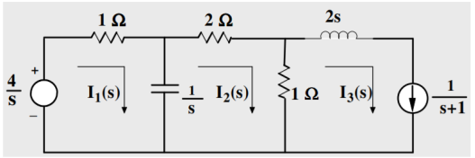
Figure 4. Laplace network
Mesh 1:
(s+1)/s I1(s) – I2(s)/s = 4/s
(s+1) I1(s) – I2(s) = 4
Mesh 2:
-1/s I1(s) + 3s+1/s I2(s) – I3(s) =0
-1/s I1(s) + 3s+1/s I2(s) – 1/s+1 =0
-I1(s) + (3s+1) I2(s) = s/s+1
-(s+1) I1(s) + (s+1)(3s+1) I2(s) = s
Adding these two equations we get
S(3s+4) I2(s) = s+4
I2(s) = (1/3) (s+4)/ s(s+4/3) = 1/s -2/3/ s+4/3
i2(t) = [ 1-2/3 e -4/3 t ] u(t)
-I1(s) + 3s+1/s . [1/s -2/3 /s+4/3] =s/s+1
-I1(s) = s/s+1 – 3s+1/s[ 1/s -2/3/s+4/3]
Key Takeaways:
Laplace techniques convert circuits with voltage and current signals that change with time to the s-domain so you can analyse the circuit's action using only algebraic techniques.
Using Laplce transform solve the differential equations :
y” – 3y’ -4y = -16x
y(0) = -4
y’(0) = -5
Apply the operator L to both sides of the differential equation; then use linearity, the initial conditions,
L[ y” – 3y’ -4y] = L[-16x]
L[ y”] – 3L[y’] -4L[y] = L[-16x]
[p 2 L[y] – p y’(0)] –[p L[y] – y[0]] – 4 L[y] = L[-16x]
p 2 L[y] +4p+5]-3[pL[y] +4] -4L[y] = -16/p2
(p2 -3p-4) L[y] + 4p -7 = -16/p2
L[y] = -16/p2 -4p +7/p2 – 3p -4
But the partial fraction decomposition of this expression for L[ y] is
-16/p2 -4p+7/ p2 -3p-4 = -16/p2 -4p+7/ p2 -3p-4 = -16-4p3+7p2/ p2(p+1)(p-4)
= -3/p + 4/p2 +1/p+1 +-2/p-4
Therefore,
y= L-1 [-3/p + 4/p2 + 1/p+1+-2/p-4]
Which yields
y=-3 +4x+e-x -2 e 4x
Key Takeaways:
The first step in using Laplace transforms to solve an IVP is to take the transform of every term in the differential equation
Given an analog signal x(t) the discrete time signal is represented by a sequence of weighted and delayed impulses.

Figure 5. Discrete time signal
A discrete time system is a mathematucal algorithm that takes an input sequence x[n] and produces output sequence y[n].
For any given sequence x[n] its z-transform is defined as :
X(z) =  z -n
z -n
= …….+x[-2] z2 + x[-1] z1 + x[0] zo + x[1] z -1 + x[2] z -2 +……..
Where z is complex variable.
Given xn=un that is step function input to the system
G(z) = 1/(1-0.9z-1) Then output yn is given by
Y(z) = G(z) X(z)
X(z) = z(un) = 1/1-z-1
Y(z) = G(z) . 1/1-z-1
Yn = z-1(G(z) / 1-z-1)
= z-1 ( 1/1-0.9 z-1 ). 1(1-z-1)
= 1/(1-0.9 z-1 )(1-z-1) = -0.9 / 1-0.9z-1 + 10/ 1-z-1
Yn = -9(0.9) n + 10
Poles are the values of z that make the denominator zero, and zeros are the values of z that make the numerator go to zero.
G(z) = 1/ 1+0.2 z-1 -0.48 z-2
= z 2/ z2 +0.2 z-0.48
= z2 / (z+0.8) (z-0.6)
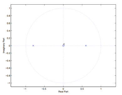
Figure 6. Poles and Zeros
Lets look at the system G(z)
G(z) = 1/1-az-1
The system has a pole at z=a and zero at z=0.
The impulse response of the system above is hn= an
Hence  =
=  a n |=
  n.
n.
For the system to be stable it must have finite sum. As  a n represents geometric expression te sum is finite if and only if |a|<1.
That means that the POLE must be within the unit circle!
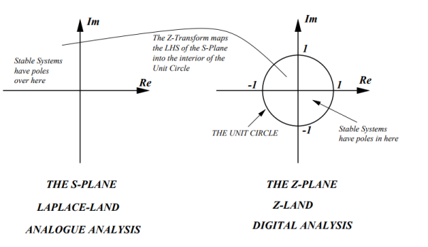
Figure 7. s-plane to z-plane
Key Takeaways:
The Z-transform converts a discrete-time signal, which is a sequence of real or complex numbers, into a complex frequency-domain representation.
References:
- Signals and Systems by Simon Haykin
- Signals and Systems by Ganesh Rao
- Signals and Systems by P. Ramesh Babu
- Signals and Systems by Chitode