Unit - 5
Information theory and coding
The meaning of the word “information” in Information Theory is the message or intelligence. The message may be an electrical message such as voltage, current or power or speech message or picture message such as facsimile or television or music message.
A source which produces these messages is called Information source.
Basics of Information System
Information system can be defined as the message that is generated from the information source and transmitted towards the receiver through transmission medium.
The block diagram of an information system can be drawn as shown in the figure.

Information sources can be classified into
- Analog Information Source
- Digital Information Source
Analog Information source such as microphone actuated by speech or a TV camera scanning a scene, emit one or more continuous amplitude electrical signals with respect to time.
Discrete Information source such as teletype or numerical output of computer consists of a sequence of discrete symbols or letters.
An analog information source can be transformed into discrete information source through the process of sampling and quantizing.
Discrete Information source are characterized by
- Source Alphabet
- Symbol rate
- Source alphabet probabilities
- Probabilistic dependence of symbol in a sequence.
In the block diagram of the Information system as shown in the figure, let us assume that the information source is a discrete source emitting discrete message symbols S1, S2………………. Sq with probabilities of occurrence given by P1, P2…………. Pq respectively. The sum of all these probabilities must be equal to 1.
Therefore P1+ P2 + ………………. + Pq = 1----------------------(1)
Or  --------------------(2)
Symbols from the source alphabet S = {s1, s2……………….sn} occurring at the rate of “rs” symbols/sec.
The source encoder converts the symbol sequence into a binary sequence of 0’s and 1s by assigning code-words to the symbols in the input sequence.
Transmitter
The transmitter couples the input message signal to the channel. Signal processing operations are performed by the transmitter include amplification, filtering and modulation.
Channel
A communication channel provides the electrical connection between the source and the destination.The cahnnel may be a pair of wires or a telephone cable or a free space over the information bearing symbol is radiated.
When the binary symbols are transmitted over the channel the effect of noise is to convert some of the 0’s into 1’s and some of the 1’s into 0’s. The signals are then said to be corrupted by noise.
Decoder and Receiver
The source decoder converts binary output of the channel decoder into a symbol sequence. Therefore the function of the decoder is to convert the corrupted sequence into a symbol sequence and the function of the receiver is to identify the symbol sequence and match it with the correct sequence.
Let us consider a zero memory space producing independent sequence of symbols with source alphabet
S = {S1,S2,S3………………Sq} with probabilities P = {P1,P2,P3……..Pq} respectively.
Let us consider a long independent sequence of length L symbols . This long sequence then contains
P1 L number of messages of type S1
P2L number of messages of type S2
……
……
PqL number of messages of type Sq.
We know that the self information of S1 = log 1/P1 bits.
Therefore
P1L number of messages of type S1 contain P1L log 1/P1 L bits of information.
P2L number of messages of type S2 contain P2L log 1/P2L bits of information.
Similarly PqL number of messages of type Sq contain PqL log 1/PqL bits of information.
The total self-information content of all these message symbols is given by
I total = P1L log 1/P1 + P2L log 1/P2 +……….+ PqL log 1/Pq bits.
I total = L  log 1/Pi
Average self-information = I total /L
=  log 1/Pi bits/msg symbol.
Average self-information is called ENTROPY of the source S denoted by H(s).
H(s)=  log 1/Pi bits/message symbol.
Thus H(s) represents the average uncertainity or the average amount of surprise of the source.
Example 1:
Let us consider a binary source with source alphabet S={S1,S2} with probabilities
P= {1/256, 255/256}
Entorpy H(s) =  log 1/Pi
= 1/256 log 256 + 255/256 log 256/255
H(s) = 0.037 bits / msg symbol.
Example 2:
Let S = {S3,S4} with P’ = {7/16,9/16}
Then Entropy H(s’) = 7/16 log 16/7 + 9/16 log 16/9
H(s) = 0.989 bits/msg symbol.
Example 3:
Let S” = {S5,S6} with P” = {1/2,1/2}
Then Entropy H(S”) = ½ log2 2 + ½ log 2 2
H(S”) = 1 bits/msg symbol.
In this case the uncertainity is maximum for a binary source and becomes impossible to guess which symbol is transmitted.
Zero memory space:
It represents a model of discrete information source emitting a sequence of symbols from S= {S1,S2………………….. Sq} successive symbols are selected according to some fixed probability law and are statistically independent of one another. This means that there is no connection between any two symbols and that the source has no memory.Such type of source are memoryless or zero memory sources.
Information rate
Let us suppose that the symbols are emitted by the source at a fixed time rate “rs” symbols/sec. The average source information rate “Rs” in bits/sec is defined as the product of the average information content per symbol and the message symbol rate “rs”
Rs = rs H(s) bits/sec
Consider a source S={S1,S2,S3} with P={1/2,1/4,1/4}
Find
a) Self information
b) Entropy of source S
a) Self information of S1 = I1 = log 21/P1 = Log 2 2 = 1 bit
Self information of S2 = I2 = log 2 1/P2 = Log 2 4 = 2 bits
Self information of S3 = I3 = log 2 1/P3 = Log 2 4 = 2 bits
b) Average Information content or Entropy =
H(s) =  Ii
Ii
= I1 P1 + I2 P2 + I3 P3
= ½(1) + ¼(2) + ¼ (2)
= 1.5 bits/msg symbol.
Q. The collector volatge of a certain circuit lie between -5V and -12V.The voltage can take only these values -5,-6,-7,-9,-11,-12 volts with the respective probabilities 1/6,1/3,1/12,1/12,1/6,1/6. This voltage is recorded with a pen recorder. Determine the average self information associated with the record in terms of bits/level.
Given Q = 6 levels. P= {1/6,1/3,1/12,1/12,1/6,1/6}
Average self-information H(s) =  log 2 1/Pi
= 1/6 log 26 + 1/3 Log 23 + 1/12 log 2 12 + 1/12 log 2 12 + 1/6 Log 26 + 1/6 Log 26
H(s) = 2.418 bits/level
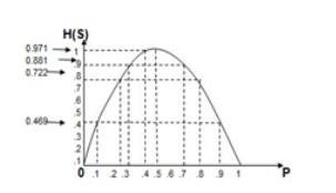
Q. A binary source is emitting an independent sequence of 0s and 1s with probabilities p and 1-p respectively. Plot entopy of source versus p.
The entropy of the binary source is given by
H(s) =  log 1/Pi
= P1 log 1/P1 + P2 log 1/P2
= P log (1/P) + (1-P) log 1/(1- P)
P=0.1 = 0.1 log(1/0.1) + 0.9 log(1/0.9)
= 0.469 bits/symbol.
At p=0.2
0.2 log(1/0.2) + 0.8 log(1/0.8)
= 0.722 bits/symbol.
At p=0.3
0.3 log(0.3) + 0.7 log(1/0.7)
= 0.881 bits/symbol.
At p=0.4
0.4 log(0.4) + 0.6 log(1/0.6)
= 0.971 bits/symbol.
At p=0.5
0.5 log(0.5) + 0.5 log(1/0.5)
= 1 bits/symbol.
At p=0.6
H(s) = 0.6 log (1/0.6) + 0.4 log(1/0.4)
H(s) = 0.971 biys/symbol
At p=0.7
0.7 log(1/0.7) + 0.3 log(1/0.3)
= 0.881 bits/symbol.
At p=0.8
0.8 log (1/0.8) +0.2 log(1/0.2)
0.722 bits/symbol
At p=0.9
0.9 log(1/0.9) + 0.1 log(1/0.1)
=0.469 bits /symbol.
Q. Let X represent the outcome of a single roll of a fair die. What is the entropy of X?
Since a die has six faces , Probability of getting any number is 1/6.
Px = 1/6.
So entropy of X = H(X) = Px log 1/Px = 1/6 log 6 = 0.431 bits / msg symbol.
Q. Find the entopy of the source in bits/symbol of the source that emits one out of four symbols A,B,C and D in a statistically independent sequences with probabilities ½,1/4,1/8 and 1/8 .
The entropy of the source is given by
H(s) =  log 1/Pi
= Pa log 1/Pa + Pb log 1/Pb + Pc log 1/Pc + Pd log 1/Pd
= ½ log 2 2 + ¼ log 2 4 + 1/8 log 2 8 + 1/8 log 2 8
H(s) = 1.75 bits/msg symbol.
1 nat = 1.443 bits
1bit = 1/1.443 = 0.693 nats.
Entropy of the souce H(s) = 1.75 X 0.693 =
H(s) = 1.213 nats/symbol.
Properties
- The entropy function for a source alphabet S = {S1,S2,S3 ……………….. Sq} with probability
P = { P1,P2,P3………………….Pq} where q = no of source symbols as
H(s) =  log (1/Pi) =
  bits/symbol.
The properties can be observed as :
The entropy function is continuous for every independent variable Pk in the interval (0,1) that is if Pk varies continuously from 0 to 1 , so does the entropy function.
The entropy function vanishes at both Pk = 0 and pk =1 that is H(s) = 0.
- The entropy function is symmetrical function of its arguments
H[Pk,(1-Pk)]= H[(1-Pk),Pk]
The value of H(s) remains the same irrespective of the location of the probabilities.
If PA = { P1,P2,P3}
PB = { P2, P3,P1}
PC = { P3,P2,P1}
Then H(SA) = H(SB) = H(SC)
- Extremal Property
Let us consider the source with “q “ symbols S={S1,S2……… Sq} with probabilities P = {P1,P2,………Pq}.Then the entropy is given by
H(s) =  log 1/Pi -------------------------(1)
And we know that
P1 +P2 + P3 ……………. Pq =  = 1
= 1
Let us now prove that
Log q – H(s) =  ] log q -
  log (1/Pi) ]-------------------------(2)
= [ log q - log (1/Pi)]---------------------------------(3)
= [ log qPi]----------------------------------(4)
=  [Log e q Pi] / [Log e 2 ]--------------------------(5)
Log q – H(s) = log 2 e  ln qPi ------------------------------(6)
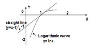
From the graph it is evident that the straight line y=x-1 always lies above the logarithmic curve y = ln x except at x=1. Thus the straight line forms the tangent to the curve at x=1.
Therefor ln x ≤ x-1
Multipling (-1) on both sides we get
-ln x ≥ 1-x or ln 1/x ≥ 1-x -------------------(7)
If X = 1/qp then ln qp ≥ 1 – 1/qp-----------------------(8)
Multipling equation 2 both sides by Pi and taking summation we get for all i=1 to q we get
 ln q Pi ≥
  [ 1 – 1/qPi] ---------------------------(9)
Multiplying eq(3) by log 2 e we get
Log 2 e  ln q Pi ≥ Log 2 e [
 -
-  -----------------------(10)
From equation (6 )
LHS of log q – H(s) and RHS of eq(6) is zero [ Since [ -
-  =0]
=0]
Therefore log q – H(s) = 0
Or H(s) ≤ log 2 q ; Suppose Pi -1/q =0 ; Pi = 1/q for all i=1,2,3………… q which satisfies then
H(s) max = log 2 q bits/msg symbol.
Property of Additivity
Suppose that we split the symbol sq into n sub symbols such that sq = sq1,sq2……….sqn with probabilities Pq1,Pq2,Pq3………………………….. Pqn such that
Pqj = Pq1 + Pq2 + Pq3 +………………….. +Pqn = 
Then the splitted symbol entropy is
H(s’) = H(P1,P2,P3………Pq-1,Pq1,Pq2………Pqn)
=  log (1/Pi) +
  log 1/Pqj
H’(s) =  log (1/Pi) –
  log 1/Pq +
  log 1/Pqj
H’(s) =  log (1/Pi) +
  [log 1/Pqj- [log 1/Pq]
=  log (1/Pi) + Pq
  [ log Pq/Pqj]
H(s) = H(s)
Therefore H’(s) ≥ H(s)
That is partitioning of symbols into sub symbols cannot decrease entropy
The source effeciency

Source Redunancy

Verify that the rule of additivity for the following source S= {S1,S2,S3,S4} with P={1/2,1/3,1/12,1/12}
The entropy H(s) is given by
H(s) =  log 1/Pi
= ½ log 2 2 + 1/3 log 2 3 + 2 x 1/12 log 2 12
H(s) = 1.6258 bits/msg symbol.
From additive property we have
H’(s) = P1 log (1/P1) + (1-P1) log 1/(1-P1)
= (1-P1){ P2/(1-P1) log (1-P1)/P2 + P3/(1-P1) log(1-P1)/P3 + P4/(1-P1) log (1-P1)/P4
= 1/2 log 2 + ½ Log 2 + ½ { (1/3)/(1/2) log(1/2)/(1/2) + (1/12)/1/2 log(1/12)/(1/2) + (1/12)/(1/2) log (1/2) /(1/12)
H’(s) = 1.6258 bits/symbol.
Q. A discreter message source S emits two independent symbols X and Y with probabilities 0.55 and 0.45 respectively. Calculate the effeciency of the source and its redundancy.
Given H(s) =  log 1/Pi
Px log 1/Px + Py log 1/Py
= 0.55 log 1/0.55 + 0.45 log 1/0.45
= 0.9928 bits/msg symbol.
The maximum entropy is given by
H(s) max = log 2 q = log 2 2 = 1 bits/symbol.
The source effeciency is given by
 = H(s) max/ H(s) = 0.9928/1 = 0.9928
 = 99.28 %
The source redundacy is given by
Rs = 1- = 0.0072
Rns = 0.72%
Discrete time signal:
If a discrete variable x(t) is defined at discrete time then x(t) is a discrete time signal. A discrete time signal is often identified as a sequence of number denoted by x(n), where ‘n’ is an integer.
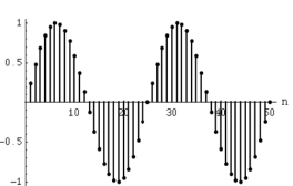
Fig: Discrete time signal
Continuous
A signal, of which a sinusoid is only one example, is a set, or sequence of numbers. The term “analog” refers to the fact that it is “analogous” of the signal it represents. A “real-world” signal is captured using a microphone which has a diaphragm that is pushed back and forth according to the compression and rarefaction of the sounding pressure waveform. The microphone transforms this displacement into a time-varying voltage—an analog electrical signal.
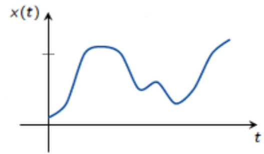
Fig: Continuous Signal
The meaning of the word “information” in Information Theory is the message or intelligence. The message may be an electrical message such as voltage, current or power or speech message or picture message such as facsimile or television or music message.
A source which produces these messages is called Message source.
It represents a model of discrete information source emitting a sequence of symbols from S= {S1,S2………………….. Sq} successive symbols are selected according to some fixed probability law and are statistically independent of one another. This means that there is no connection between any two symbols and that the source has no memory.Such type of source are memoryless or zero memory sources.
The output symbols emitted from this kind of sources are independent on each other (i.e. the current emitted symbol is independent on the previous one). Those symbols are considered discrete random variables because at any time instant we don't know exactly what will be the next output symbol. The existence of any symbol is determined according to its probability which is predetermined before the real operation of the source in the stage source testing.
The probability of any symbol is a measurement of how frequently the symbol is repeated. Let's consider ZMS emitting q symbols {S1, S2, . . . , Sq} each symbol is repeated with number of times given by {n1 , n2 , . . . , nq} so the probability of symbol Si is given by
P(Si) = 
 =1
=1
The analysis of any information source basically depends on the knowledge of the probabilities set {P(S1) , P(S2) , . . . , P(Sq)}. In the coming subsections we will explain and analyze some important parameters that characterize any ZMS.
Let’s assume that there is a Markov process which has a finite state S and whose state transition matrix P is fixed. Also, there is a function of output sequence X that only depends on current and one step before states. The sequence of S goes to produce the random source X and we can only observe the output sequence X’ s. This process is called as Markov source or Markovian process. The detailed description is as following
S= {1,2,…n}
P={Pij}i,j s = Prob. Chain goes to state j / state i(given) in one step
f= S x S -{0,1}
• (y0, . . . , yt) ∈ St s.t. y0 ∈ S : initial state
• Pr [yt = j|yt−1 = i yt−1 · · · y0] = Pij
• (x0, . . . , xt) ∈ X s.t. xt = f(yt−1, yt)
There are several prime notations for Markov source
• Source is reducible if ∃i, j ∈ S with no path of prob from i to j, e.g.

• Source is L periodic if ∀C paths from i back to i has length divisible by L

We know where the state is after 4 steps.
• Source is irreducible if it is not reducible and aperiodic (:= if it is not L periodic for any L ≥2 ”irreducible + aperiodic” ⇔ ergodic
- Communication over a discrete memory less channel takes place in a discrete number of “channel uses,” indexed by the natural number n ∈ ℕ.
- The concepts use the simple two-transmitter, two-receiver channel shown in Figure.
- The primary (secondary) transmitter Ptx (Stx) wishes to communicate a message to a single primary (secondary) receiver Prx (Srx).
- The transmitters communicate their messages by transmitting codewords, which span n channel uses (one input symbol per channel use). The receivers independently decode the received signals, often corrupted by noise according to the statistical channel model, to obtain the desired message.
- One quantity of fundamental interest in such communication is the maximal rate, typically cited in bits/channel use at which communication can take place.
- Most information theoretic results of interest are asymptotic in the number of channel uses; that is, they hold in the limit as n → ∞.
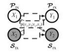
Discrete memory less channel
A channel is said to be symmetric or uniform channel if the second and subsequent rows of the channel matrix contain the same elements as that of the first row but in different order.
For example
P(Y/X) = 

Channel matrix and diagram of symmetric/uniform channel
The equivocation H(B/A) is given by
H(B/A) =  log 1/P(bi/ai)
But p (ai, bj) = P(ai) P(bj/ai)
H(B/A) = 
 log 1/P(bj/ai)
Since  log 1/P(bj/ai) = h
H(B/A) = 1.h
H=  log 1/P(j)
Therefore, the mutual information I (A, B) is given by
I (A, B) is given by H(B) –H(B/A)
I (A, B) = H(B) –h
Now the channel capacity is defined as
C = Max [I (A, B)]
= Max[H(B) – h]
C = Max[H(b) –h] -----------------------(X)
But H(B) the entropy of the output symbol becomes maximum if and only if when all the received symbols become equiprobable and since there are ‘S’ number of output symbols we have H(B) max = max[H(B) = log s----------------------(Y)
Substituting (Y) in (X) we get
C = log 2 s – h
For the channel matrix shown find the channel capacity
P(bj/ai) = 
The given matrix belongs to a symmetric or uniform channel
H(B/A) = h =  log 1/Pj
= ½ log 2 + 1/3 Log 3 + 1/6 log 6
H(B/A) = 1.4591 bits/msg symbol.
The channel capacity is given by
C = (log S – h) rs rs = 1 msgsymbol/sec
C = log 3 – 1.4591
C = 0.1258 bits/sec
Q. Determine the capacity of the channel as shown in the figure.
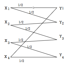
The channelmatrix can be written as
P(Y/X) = ½ ½ 0 0 |
0 ½ ½ 0 |
0 0 ½ ½ |
½ 0 0 ½ |
Now h = H(Y/X) =  log 1/Pj
H = ½ log 2 + ½ log 2 +0+ 0 = 1 bits/Msg symbol.
Channelcapacity
C = log s – h
= log 4 – 1
= 1 bits/msg symbol.
Shannon-Hartley law states that the capacity of a band limited Gaussian channel with AWGN is given by
C = B log(1+B/N) bits/sec
Where B ----- channel bandwidth in Hz
S ----------------------- signal power in watts
N ------------------------- noise power in watts.
Proof: Consider the channel capacity ‘C’ given by
C = [H(Y) – H(N) ] max------------------------(1)
But
H(N) max = B log 2π e N bits/sec
H(Y) max = B log 2π e 
 2 bits/sec
But 
 2 = S + N
H(Y) max = B log 2π e (S+N) bits/sec
C = = B log 2π e (S+N) - = B log 2π e N
C = B log 2π e (S+N)/ 2π e N
C = B log (S+N)/N
C = B log (1+S/N) bits/sec
1. A voice grade channel of the telephone network has a bandwidth of 3.4KHz
- Calculate the channel capacity of the telephone channel for a signal to noise ratio of 30db
- Calculate the minimum signalto noise ratio required to support information through the telephone channel at the rate of 4800 bits/sec
Given :
Bandwidth = 3.4 KHz
10 log 10 S/N = 30 db
S/N = 10 3 = 1000
Channel capacity
C = B log 2 (1+S/N) = 3400 log (1 + 1000)
C = 33889 bits/sec
Given C = 4800 bits/sec
4800 = 3400 log 2(1+S?N)
S/N = 2 48/34 - 1
S/N = 1.66
S/N = 10 log 1.66 = 2.2 db
S/N = 2.2 db
2. An analog signal has a 4 Khz bandwidth . The signal is sampled at 2.5 times the Nyquist rate and each sample quantized into 256 equally likely levels. Assume that the successive samples are statistically independent.
- Find the information rate of the source
- Can the output of the source be transmitted without error over the Gaussian channel of bandwidth 50Hz and S/N ratio of 20db
- If the output of the source is to be transmitted without errors over an analog channel having S/N of 10 db , Compute bandwidth requirement of the channel.
Given B = 4000Hz Therefore Nyquist rate = 2B = 8000Hz
Sampling rate rs = 2.5 Nyquist rate
= 2.5 x 8000 = 20,000 samples/sec
Since all the quantization levels are equal likely the maximum information content
I = log e q = log 2 256 = 8 bits /sample.
Information rate Rs = rs .I = 20,000 X 8 = 1,60,000 bits/sec
From Shannon’s Hartley law
C = B log (1+ S/N)
C = 332.91 x 10 3 bits/sec
Iii)
C = B log (1+S/N) = Rs
B = Rs/log(1+S/N) = 46.25 KHz
B = 46.25 KHz.
• A code is uniquely decodable if the mapping C+: A+X → A+Z is one-to-one, i.e. ∀ x and x’ in A+X, x  ⇒ c+(x’)
  c+(x’)
• A code is obviously not uniquely decodable if two symbols have the same codeword — ie, if c(ai) = c(aj) for some i j — so we’ll usually assume that this isn’t the case.
• A code is instantaneously decodable if any source sequences x and x’ in A+ for which x is not a prefix of x’ have encodings z = C(x) and z’ = C(x’) for which z is not a prefix of z’. Otherwise, after receiving z, we wouldn’t yet know whether the message starts with z or with z’.
• Instantaneous codes are also called prefix-free codes or just prefix codes.
• Easiest case: assume the end of the transmission is explicitly marked, and don’t require any symbols to be decoded until the entire transmission has been received.
• Hardest case: require instantaneous decoding, and thus it doesn’t matter what happens at the end of the transmission.
| Code A | Code B | Code C | Code D |
a | 10 | 0 | 0 | 0 |
b | 11 | 10 | 01 | 01 |
c | 11 | 110 | 011 | 11 |
Code A: Not uniquely decodable Both bbb and cc encode as 111111
Code B: Instantaneously decodable End of each codeword marked by 0
Code C: Decodable with one-symbol delay End of codeword marked by following 0
Code D: Uniquely decodable, but with unbounded delay:
011111111111111 decodes as accccccc
01111111111111 decodes as bcccccc
| Code E | Code F | Code G |
a | 100 | 0 | 0 |
b | 101 | 001 | 01 |
c | 010 | 010 | 011 |
d | 011 | 100 | 1110 |
Code E: Instantaneously decodable All codewords same length
Code F: Not uniquely decodable e.g. Baa, aca, aad all encode as 00100
Code G: Decodable with six-symbol delay.
Check for Unique De codability
For a uniquely decodable code with source set  id l(x) is the length of a codeword with x
 then Kraft’s Inequality is satisfied.

A prefix code is a kind of uniquely decodable code in which no valid codeword is a prefix of any other codeword. These are generally easier to understand and construct.
Theorem 1 For any uniquely decodable code C, let L(C) be the average number of bits per symbol, p(x) be the probability of the occurrence of symbol x, and H(X) be the entropy of the source. Then
L(C) = 
Theorem 1 signifies that the entropy function puts a fundamental lower bound on the average number of bits per symbol.
Proof:
L(C) - H(X) 
= - 
= - 
Now we can see that
0
Finally, we conclude to
- 
But,

Change the base of the logarithm in the first term from 2 to e using the change of base formula for logs.
- 
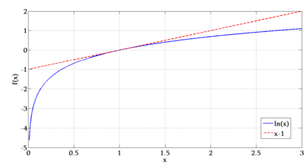
The tangent line to the curve of ln(x) at x = 1 is f(x) = x − 1. It follows that ln(x) ≤ x – 1
-  ≥ −
≥ −
 )
)
Consider the term  . Distributing this becomes
  . The right hand side of above equation is satisfied to
-
From Kraft’s Inequality, this sum is always less than or equal to 1. Since − log2 (1) = 0, L(C) ≥ H(X). This holds for any uniquely decodable code.
Key takeaway
If loge (x) ≡ ln(x) is used, the unit that follows is nats instead of bits.
A code is instantaneous if and only if no codeword is a prefix of some other codeword. (ie if Ci is a codeword, Ci Z cannot be a codeword for any Z). This is a prefix code.
Proof:
(⇒) If codeword C(ai) is a prefix of codeword C(aj), then the encoding of the sequence x = ai is obviously a prefix of the encoding of the sequence x’ = aj.
(⇐) If the code is not instantaneous, let z = C(x) be an encoding that is a prefix of another encoding z’ = C(x’), but with x not a prefix of x’, and let x be as short as possible.
The first symbols of x and x’ can’t be the same, since if they were, we could drop these symbols and get a shorter instance. So, these two symbols must be different, but one of their codewords must be a prefix of the other.
• Since we hope to compress data, we would like codes that are uniquely decodable and whose codewords are short.
• Also, we’d like to use instantaneous codes where possible since they are easiest and most efficient to decode.
• If we could make all the codewords really short, life would be really easy. Too easy. Because there are only a few possible short codewords and we can’t reuse them or else our code wouldn’t be decodable.
• Instead, making some codewords short will require that other codewords be long, if the code is to be uniquely decodable
Key takeaway
Since instantaneous codes are a proper subset of uniquely decodable codes, we might have expected that the condition for existence of a u.d. Code to be less stringent than that for instantaneous codes.
Kraft’s Inequality
• There is an instantaneous binary code with codewords having lengths l1, . . . , lI if and only if

• This is exactly the same condition as McMillan’s inequality!
• E.g. There is an instantaneous binary code with lengths 1, 2, 3, 3, since 1/2 + 1/4 + 1/8 + 1/8 = 1
• An example of such a code is {0, 10, 110, 111}.
• There is an instantaneous binary code with lengths 2, 2, 2, since 1/4 + 1/4 + 1/4 < 1 • An example of such a code is {00, 10, 01}.
McMillan’s Inequality
There is a uniquely decodable binary code with codewords having lengths l1, . . . , lI if and only if

• E.g. There is a uniquely decodable binary code with lengths 1, 2, 3, 3, since 1/2 + 1/4 + 1/8 + 1/8 = 1
• An example of such a code is {0, 01, 011, 111}.
• There is no uniquely decodable binary code with lengths 2, 2, 2, 2, 2, since 1/4 + 1/4 + 1/4 + 1/4 + 1/4 > 1
Proof of above two inequalities
• We can prove both Kraft’s and McMillan’s inequality by proving that for any set of lengths, l1, . . . , lI , for binary codewords:
A) If,  we can construct an instantaneous code with codewords having these lengths.
B) If  > 1, there is no uniquely decodable code with codewords having these lengths.
(A) is half of Kraft’s inequality.
(B) is half of McMillan’s inequality.
• Using the fact that instantaneous codes are uniquely decodable,
(A) gives the other half of McMillan’s inequality, and (B) gives the other half of Kraft’s inequality.
• To do this, we’ll introduce a helpful way of thinking about codes as...trees.
• We can view codewords of an instantaneous (prefix) code as leaves of a tree.
• The root represents the null string; each level corresponds to adding another code symbol.
• Here is the tree for a code with codewords 0, 11, 100, 101
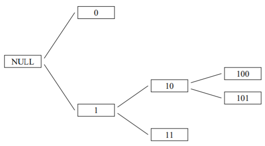
The section below further shows how the inequality is proved.
• Suppose that Kraft’s Inequality holds:

Order the lengths so l1 ≤ · · · ≤ lI .
• In the binary tree with depth lI, how can we allocate subtrees to codewords with these lengths?
• We go from shortest to longest, i = 1, . . . , I:
1) Pick a node at depth li that isn’t in a subtree previously used, and let the code for codeword i be the one at that node.
2) Mark all nodes in the subtree headed by the node just picked as being used, and not available to be picked later.
Let’s look at an example
• We can extend the tree by filling in the subtree underneath every actual codeword, down to the depth of the longest codeword.
• Each codeword then corresponds to either a leaf or a subtree.
• Previous tree extended, with each codeword’s leaf or subtree circled:
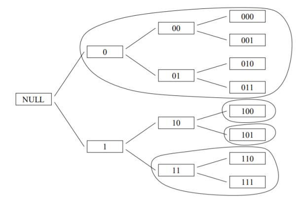
• Short codewords occupy more of the tree. For a binary code, the fraction of leaves taken by a codeword of length l is 1/2l.
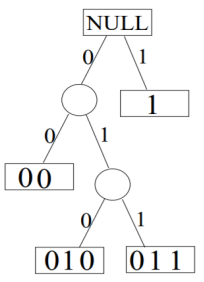
• Let the lengths of the codewords be {1,2,3,3}.
• First check: 2−1 + 2−2 + 2−3 + 2−3 ≤ 1.
• Our final code can be read from the leaf nodes: {1,00,010,011}.
• If Kraft’s inequality holds, we will always be able to do this.
• To begin, there are 2lb nodes at depth lb.
• When we pick a node at depth la, the number of nodes that become unavailable at depth lb (assumed not less than la) is 2lb−la.
• When we need to pick a node at depth lj, after having picked earlier nodes at depths li (with i < j and li ≤ lj), the number of nodes left to pick from will be

First the source symbols are listed in the non-increasing order of probabilities
Consider the equation
q = r + (r-1 ) 
Where q = number of source symbols
r = no of different symbols used in the code alphabet
The quantity  is calculated and it should be an integer . If it is not then dummy symbols with zero probabilities are added to q to make the quantity )
  an integer. To explain this procedure consider some examples.
Shannon-Fano coding
Shanon-Fano Encoding procedure for getting a compact code with minimum redundancy is given below:
- The symbols are arranged according to non-increasing probabilities
- The symbols are divided into two groups so that the su of probabilities in each group is approximately equal.
- All the symbols in the first group are designated by “1” and the second group by “0.
- The first group is again subduivided into two subgrous such that rach subgroup probabilities are approximately same.
- All the symbols of the first subgroup are designated by 1 and second subgroup by 0
- The second subgroup is subdivided into two or more subgropus and step 5 is repeated.
- This process is continued till further sub-division is impossible.
Given are the messages X1,X2,X3,X4,X5,X6 with respective probabilities 0.4,0.2,0.2,0.1,0.07 and 0.03. Construct a binary code by applying Shannon-fano encoding procedure . Determine code effeciency and redundancy of the code.
Applying Shannon-fano encoding procedure

Average length L is given by
L = 
= 0.4 x 1 + 0.2 x 3 + 0.2 x 3 + 0.1 x 3 + 0.07 x4 + 0.03 X 4
L = 2.3 bits/msg symbol.
Entropy
H(s) =  log 1/Pi
0.4 log 1/0.4 + 2x 0.2 log 1/0.2 + 0.1 log 1/0.1 + 0.07 log 1/0.07 + 0.03 log 1/0.03
H(s) = 2.209 bits/msg symbol.
Code Efficiency = ηc = H(s) / L = 2.209/2.03 = 96.04%
Code Redundancy = R ηc = 1- ηc = 3.96%
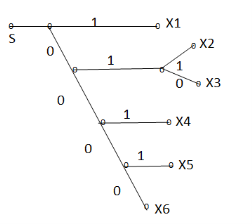
Q. You are given four messages X1 , X2 , X3 and X4 with respective probabilities 0.1,0.2,0.3,0.4
- Device a code with pre-fix property (Shannon fano code) for these messages and draw the code.
- Calculate the efficiency and redundancy of the code.
- Calculate the probabilities of 0’s and 1’s in the code.
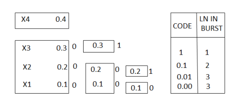
Average length L =  li
li
= 0.4 x1 + 0.3 x 2 + 0.2 x 3 + 0.1 x3
L = 1.9 bits/symbol.
Entropy H(s) =  log 1/Pi
= 0.4 log 1/0.4 + 0.3 log 1/0.3 + 0.2 log 1/0.2 + 0.1 log 1/0.1
H(s) = 1.846 bits/msg symbol.
Code efficiency ηc = H(s) / L = 1.846/1.9 = 97.15%
Code Redundancy = R ηc = 1- ηc = 2.85%
The code tree can be drawn
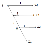
The probabilities of 0’s and 1’s in the code are found by using the
P(0)= 1/L  no of 0’s in code xi) (Pi)
= 1/1.9 [ 3 x 0.1 + 2x 0.2 + 1x 0.3 + 0(0.4)]
P(0) = 0.5623
P(1) = 1/L  no of 1’s in code xi) (Pi)
= 1/1.9 [ 0x0.1+1x0.2+1x0.+1x0.4]
P(1) = 0.4737
In channel encoder a block of k-msg bits is encoded into a block of n bits by adding (n-k) number of check bits as shown in figure.
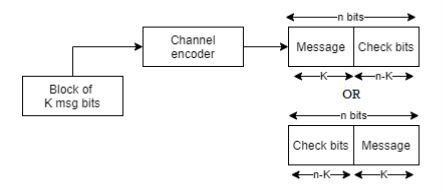
Fig: Linear Block Code
A (n,k) block code is said to be a (n,k) linear block code if it satisfies the condition
Let C1 and C2 be any two code words belonging to a set of (n,k) block code
Then C1C2 is also an n-bit code word belonging to the same set of (n,k ) block code.
A (n,k) linear block code is said to be systematic if k-msg bits appear either at the beginning or end of the code word.
Matrix Description of linear block codes:
Let the message block of k-bits be represented as row vector called as message vector given by
[D ] = { d1,d2………………dk}
Where d1,d2………………dk are either 0’s 0r 1’s
The channel encoder systematically adds(n-k) number of check bits toform a (n,k) linear block code. Then the 2k code vector can be represented by
C = {c1,c2……………cn) ----------------------------(2)
In a systematic linear block code the msg bits appear at the beginning of the code vector
Therefore ci=di for all I = 1 to k.---------------------------------(3)
The remaining n-k bits are check bits . Hence eq(2) and (3) can be combined into
[C] = { C1,C2,C3……………………..Ck, Ck+1,Ck+2 ……………………Cn}
These (n-k) number of check bits ck+1,Ck+2 ………………. Cn are derived from k-msg bits using predetermined rule below:
Ck+1 =P11d1 + P21 d2 +………………….+ Pk1dk
Ck+2 = P21 d1 + P22 d2 +………………….+ Pk2dk
……………………………………………………….
Ck+n = P1,n-kd1+ P2,n-k d2 + ……………………+ Pk,n-kdk
Where P11,P21 …………. Are either 0’s or 1’s addition is performed using modulo 2 arithmetic
In matrix form
[c1 c2………….cn] = [d1,d2…………………dn] [ 1 0 0 0 P11 P12 ……….P1n-k]
--------------------------
0 0 0 Pk1…………………… Pk,n-k
0r [C] = [D] [G]
[G] = [Ik |P](kxn)
Where Ik is the unit matrix of order ‘k’
[P] = parity matrix of order kx (n-k)
I = denotes demarkation between Ik and P
The generator matrix can be expressed as
[G] = [P | Ik]
Associted with the generator matrix [G] another matrix order (n-k) x n matrix is called the parity check matrix.
Given by
[H ] = [ PT | I n-k]
Where PT represents parity transpose matrix.
Examples
Q1) The generator matrix for a block code is given below. Find all code vectors of this code

A1) The Generator matrix G is generally represented as


On comparing,
The number of message bits, k = 3
The number of code word bits, n = 6
The number of check bits, q = n – k = 6 – 3 = 3
Hence, the code is a (6, 3) systematic linear block code. From the generator matrix, we have Identity matrix

The coefficient or submatrix,

Therefore, the check bits vector is given by,

On substituting the matrix form,

From the matrix multiplication, we have


On simplifying, we obtain


Hence the check bits (c1 c2 c3) for each block of (m1 m2 m3) message bits can be determined.
(i) For the message block of (m1 m2 m3) = (0 0 0), we have


(ii) For the message block of (m1 m2 m3) = (0 0 1), we have


(iii) For the message block of (m1 m2 m3) = (0 1 0), we have


Similarly, we can obtain check bits for other message blocks.
Cyclic Codes: Coding & Decoding
Binary cyclic codes are a subclass of the linear block codes. They have very good features which make them extremely useful. Cyclic codes can correct errors caused by bursts of noise that affect several successive bits. The very good block codes like the Hamming codes, BCH codes and Golay codes are also cyclic codes. A linear block code is called as cyclic code if every cyclic shift of the code vector produces another code vector. A cyclic code exhibits the following two properties.
(i) Linearity Property: A code is said to be linear if modulo-2 addition of any two code words will produce another valid codeword.
(ii) Cyclic Property: A code is said to be cyclic if every cyclic shift of a code word produces another valid code word. For example, consider the n-bit code word, X = (xn-1, xn-2, ….. x1, x0).
If we shift the above code word cyclically to left side by one bit, then the resultant code word is
X’ = (xn-2, xn-3, ….. x1, x0, xn-1)
Here X’ is also a valid code word. One more cyclic left shift produces another valid code vector X’’.
X’’ = (xn-3, xn-4, ….. x1, x0, xn-1, xn-2)
Representation of codewords by a polynomial
• The cyclic property suggests that we may treat the elements of a code word of length n as the coefficients of a polynomial of degree (n-1).
• Consider the n-bit code word, X = (xn-1, xn-2, ….. x1, x0)
This code word can be represented in the form of a code word polynomial as below:
X (p) = xn-1p n-1 + xn-2pn-2 + ….. + x1p + x0
Where X (p) is the polynomial of degree (n-1). p is an arbitrary real variable. For binary codes, the coefficients are 1s or 0s.
- The power of ‘p’ represents the positions of the code word bits. i.e., pn-1 represents MSB and p0 represents LSB.
- Each power of p in the polynomial X(p) represents a one-bit cyclic shift in time. Hence, multiplication of the polynomial X(p) by p may be viewed as a cyclic shift or rotation to the right, subject to the constraint that pn = 1.
- We represent cyclic codes by polynomial representation because of the following reasons.
1. These are algebraic codes. Hence algebraic operations such as addition, subtraction, multiplication, division, etc. becomes very simple.
2. Positions of the bits are represented with the help of powers of p in a polynomial.
A) Generation of code vectors in non-systematic form of cyclic codes
Let M = (mk-1, mk-2, …… m1, m0) be ‘k’ bits of message vector. Then it can be represented by the polynomial as,
M(p) = mk-1pk-1 + mk-2pk-2 + ……+ m1p + m0
The codeword polynomial X(P) is given as X (P) = M(P). G(P)
Where G(P) is called as the generating polynomial of degree ‘q’ (parity or check bits q = n – k). The generating polynomial is given as G (P) = pq + gq-1pq-1+ …….. + g1p + 1
Here gq-1, gq-2 ….. g1 are the parity bits.
• If M1, M2, M3, …… etc. are the other message vectors, then the corresponding code vectors can be calculated as,
X1 (P) = M1 (P) G (P)
X2 (P) = M2 (P) G (P)
X3 (P) = M3 (P) G (P) and so on
All the above code vectors X1, X2, X3 ….. Are in non-systematic form and they satisfy cyclic property.
The generator polynomial of a (7, 4) cyclic code is G(p) = p3 + p + 1. Find all the code vectors for the code in non-systematic form
Here n = 7, k = 4
Therefore, q = n – k = 7 – 4 = 3
Since k = 4, there will be a total of 2k = 24 = 16 message vectors (From 0 0 0 0 to 1 1 1 1). Each can be coded in to a 7 bits codeword.
(i) Consider any message vector as
M = (m3 m2 m1 m0) = (1 0 0 1)
The general message polynomial is M(p) = m3p3 + m2p2 + m1p + m0, for k = 4
For the message vector (1 0 0 1), the polynomial is
M(p) = 1. p3 + 0. p2 + 0. p + 1
M(p) = P3 + 1
The given generator polynomial is G(p) = p3 + p + 1
In non-systematic form, the codeword polynomial is X (p) = M (p). G (p)
On substituting,
X (p) = (p3 + 1). (p3 + p +1)
= p6 + p4 + p3 + p3 + p +1
= p6 + p4 + (1 1) p3 + p +1
= p6 + p4 + p + 1
= 1.p6 + 0.p5 + 1.p4 + 0.p3 + 0.p2 + 1.p + 1
The code vector corresponding to this polynomial is
X = (x6 x5 x4 x3 x2 x1 x0)
X = (1 0 1 0 0 1 1)
(ii) Consider another message vector as
M = (m3 m2 m1 m0) = (0 1 1 0)
The polynomial is M(p) = 0.p3 + 1.p2 + 1.p1 + 0.1
M(p) = p2 + p
The codeword polynomial is
X(p) = M(p). G(p)
X(p) = (p2 + p). (p3 + p + 1)
= p5 + p3 + p2 + p4 + p2 + p
= p5 + p4 + p3 + (1 1) p2 + p
= p5 + p4 + p3 + p
= 0.p6 + 1.p5 + 1.p4 + 1.p3 + 0.p2 + 1.p + 0.1
The code vector, X = (0 1 1 1 0 1 0)
Similarly, we can find code vector for other message vectors also, using the same procedure.
B) Generation of code vectors in systematic form of cyclic codes
The code word for the systematic form of cyclic codes is given by
X = (k message bits ⋮q check bits)
X = (mk-1 mk-2 …….. m1 m0⋮ cq-1 cq-2 ….. c1 c0)
In polynomial form, the check bits vector can be written as
C(p) = cq-1pq-1 + cq-2pq-2 + …….. + c1p + c0
In systematic form, the check bits vector polynomial is obtained by
C(p) = rem [𝑝𝑞. 𝑀 (𝑝)/𝐺(𝑝) ]
Where:
M(p) is message polynomial
G(p) is generating polynomial
‘rem’ is remainder of the division
The generator polynomial of a (7, 4) cyclic code is G(p) = p3 + p + 1. Find all the code vectors for the code in systematic form.
Here n = 7, k = 4
Therefore, q = n - k = 7 – 4 = 3
Since k = 4, there will be a total of 2k = 24 = 16 message vectors (From 0 0 0 0 to 1 1 1 1). Each can be coded into a 7 bits codeword.
(i) Consider any message vector as
M = (m3 m2 m1 m0) = (1 1 1 0)
By message polynomial,
M(p) = m3p3 + m2p2 + m1p + m0, for k = 4.
For the message vector (1 1 1 0), the polynomial is
M(p) = 1.p3 + 1.p2 + 1.p + 0.1
M(p) = p3 + p2 + p
The given generator polynomial is G(p) = p3 + p + 1
The check bits vector polynomial is


We perform division as per the following method.
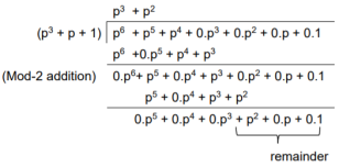
Thus, the remainder polynomial is p2 + 0.p + 0.1.
This is the check bits polynomial C(p)
c(p) = p2 + 0.p + 0.1
The check bits are c = (1 0 0)
Hence the code vector for the message vector (1 1 1 0) in systematic form is
X = (m3 m2 m1 m0⋮ c2 c1 c0) = (1 1 1 0 1 0 0)
(ii) Consider another message vector as
M = (m3 m2 m1 m0) = (1 0 1 0)
The message polynomial is M(p) = p3 + p
Then the check bits vector polynomial is


The division is performed as below.
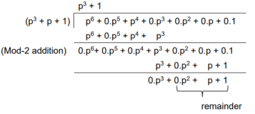
Thus, the check bits polynomial is C(p) = 0.p2 + 1.p + 1.1
The check bits are C = (0 1 1)
Hence the code vector is X= (1 0 1 0 0 1 1)
Similarly, we can find code vector for other message vectors also, using the same procedure.
Cyclic Redundancy Check Code (CRC)
Cyclic codes are extremely well-suited for error detection. Because they can be designed to detect many combinations of likely errors. Also, the implementation of both encoding and error detecting circuits is practical. For these reasons, all the error detecting codes used in practice are of cyclic code type. Cyclic Redundancy Check (CRC) code is the most important cyclic code used for error detection in data networks & storage systems. CRC code is basically a systematic form of cyclic code.
CRC Generation (encoder)
The CRC generation procedure is shown in the figure below.
- Firstly, we append a string of ‘q’ number of 0s to the data sequence. For example, to generate CRC-6 code, we append 6 number of 0s to the data.
- We select a generator polynomial of (q+1) bits long to act as a divisor. The generator polynomials of three CRC codes have become international standards. They are
- CRC – 12 code: p12 + p11 + p3 + p2 + p + 1
- CRC – 16 code: p16 + p15 + p2 + 1
- CRC – CCITT Code: p16 + p12 + p5 + 1
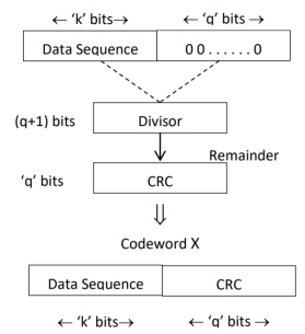
Fig: CRC Generation
- We divide the data sequence appended with 0s by the divisor. This is a binary division.
- The remainder obtained after the division is the ‘q’ bit CRC. Then, this ‘q’ bit CRC is appended to the data sequence. Actually, CRC is a sequence of redundant bits.
- The code word generated is now transmitted.
CRC checker
The CRC checking procedure is shown in the figure below. The same generator polynomial (divisor) used at the transmitter is also used at the receiver.
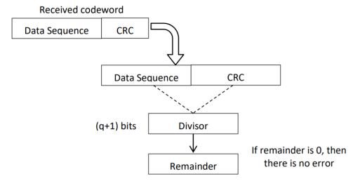
Fig: CRC checker
- We divide the received code word by the divisor. This is also a binary division.
- If the remainder is all 0s, then there are no errors in the received codeword, and hence must be accepted.
- If we have a non-zero remainder, then we infer that error has occurred in the received code word. Then this received code word is rejected by the receiver and an ARQ signaling is done to the transmitter.
1. Generate the CRC code for the data word of 1 1 1 0. The divisor polynomial is p3 + p + 1
Data Word (Message bits) = 1 1 1 0
Generator Polynomial (divisor) = p3 + p + 1
Divisor in binary form = 1 0 1 1
The divisor will be of (q + 1) bits long. Here the divisor is of 4 bits long. Hence q = 3. We append three 0s to the data word.
Now the data sequence is 1 1 1 0 0 0 0. We divide this data by the divisor of 1 0 1 1. Binary division is followed.
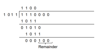
The remainder obtained from division is 100. Then the transmitted codeword is 1 1 1 0 1 0 0.
2. A codeword is received as 1 1 1 0 1 0 0. The generator (divisor) polynomial is p3 + p + 1. Check whether there is error in the received codeword.
Received Codeword = 1 1 1 0 1 0 0
Divisor in binary form = 1 0 1 1
We divide the received codeword by the divisor.
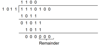
The remainder obtained from division is zero. Hence there is no error in the received codeword.
Key takeaway
- Cyclic codes can correct burst errors that span many successive bits.
- They have an excellent mathematical structure. This makes the design of error correcting codes with multiple-error correction capability relatively easier.
- The encoding and decoding circuits for cyclic codes can be easily implemented using shift registers.
- The error correcting and decoding methods of cyclic codes are simpler and easy to implement. These methods eliminate the storage (large memories) needed for lookup table decoding. Therefore, the codes become powerful and efficient.
References:
1. Bernard Sklar, Prabitra Kumar Ray, “Digital Communications Fundamentals and Applications”, Pearson Education, 2nd Edition
2. Wayne Tomasi, “Electronic Communications System”, Pearson Education, 5th Edition
3. A.B Carlson, P B Crully, J C Rutledge, “Communication Systems”, Tata McGraw Hill Publication, 5th Edition
4. Simon Haykin, “Communication Systems”, John Wiley & Sons, 4th Edition
5. Simon Haykin, “Digital Communication Systems”, John Wiley & Sons, 4th Edition.