Unit - 1
Signals and systems

Fig.1: Basic elements of DSP
To perform the processing digitally, there is a need for an interface between the analog signal and the digital processor. This interface is called an analog-to-digital (A/D) converter. The output of the A?D converter is a digital signal that is appropriate as an input to the digital processor.
The digital signal processor may be a large programmable digital computer or a small microprocessor programmed to perform the desired operations on the input signal. It may also be a hardwired digital processor configured to perform a specified set of operations on the input signal.
Programmable machines provide the flexibility to change the signal processing operations through a change in the software, whereas hardwired machines are difficult to reconfigure. Consequently, programmable signal processors are in very common use.
On the other hand, when signal processing operations are well defined, a hardwired implementation of the operations can be optimized, resulting in a cheaper signal processor and, usually, one that runs faster than its programmable counterpart.
In applications where the digital output from the digital signal processor is to be given to the user in analog form, such as in speech communications, we must provide another interface from the digital domain to analog domain. Such an interface is called a digital-to-analog (D/A) converter. Thus the signal is provided to the user in analog form.
However, there are other practical applications involving signal analysis, where the desired information is conveyed in digital form and no D/A converter is required. For example, in the digital processing of radar signals, the information extracted from the radar signal, such as the position of the aircraft and its speed, may simply be printed on paper. There is no need for a D/A converter in this case.
Analog | Digital |
An analog signal is a continuous signal that represents physical measurements. | Digital signals are time separated signals which are generated using digital modulation. |
It is denoted by sine waves | It is denoted by square waves |
It uses a continuous range of values that help you to represent information. | Digital signal uses discrete 0 and 1 to represent information. |
Temperature sensors, FM radio signals, Photocells, Light sensor, Resistive touch screen are examples of Analog signals. | Computers, CDs, DVDs are some examples of Digital signal. |
The analog signal bandwidth is low | The digital signal bandwidth is high. |
Analog signals are deteriorated by noise throughout transmission as well as write/read cycle. | Relatively a noise-immune system without deterioration during the transmission process and write/read cycle. |
Analog hardware never offers flexible implementation. | Digital hardware offers flexibility in implementation. |
It is suited for audio and video transmission. | It is suited for Computing and digital electronics. |
Processing can be done in real-time and consumes lesser bandwidth compared to a digital signal. | It never gives a guarantee that digital signal processing can be performed in real time. |
Analog instruments usually have s scale which is cramped at lower end and gives considerable observational errors. | Digital instruments never cause any kind of observational errors. |
Analog signal doesn't offer any fixed range. | Digital signal has a finite number, i.e., 0 and 1. |
The sampling theorem, which is also called as Nyquist theorem, delivers the theory of sufficient sample rate in terms of bandwidth for the class of functions that are bandlimited.
The sampling theorem states that, “a signal can be exactly reproduced if it is sampled at the rate fs which is greater than twice the maximum frequency W.”
Let us consider a band-limited signal, i.e., a signal whose value is non-zero between some –W and W Hertz.
Such a signal is represented as x(f)=0 for ∣f∣>W
For the continuous-time signal x (t), the band-limited signal in frequency domain, can be represented as shown in the following figure.
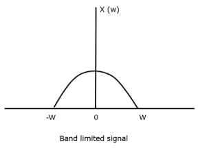
Fig 2 Band Limited Signal
If the signal x(t) is sampled above the Nyquist rate, the original signal can be recovered, and if it is sampled below the Nyquist rate, the signal cannot be recovered.
The following figure explains a signal, if sampled at a higher rate than 2w in the frequency domain.
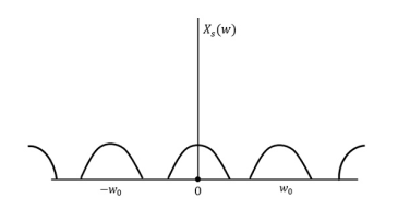
Fig 3 FT of xs(t)
The above figure shows the Fourier transform of a signal xs (t).
If fs<2W
The resultant pattern will look like the following figure.
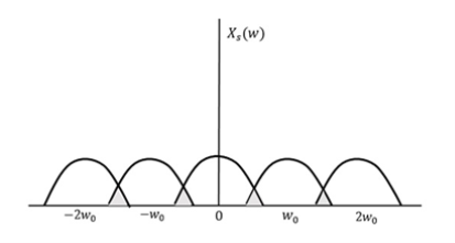
Fig 4 Resultant Signal
Here, the over-lapping of information is done, which leads to mixing up and loss of information. This unwanted phenomenon of over-lapping is called as Aliasing.
Aliasing
Aliasing can be referred to as “the phenomenon of a high-frequency component in the spectrum of a signal, taking on the identity of a low-frequency component in the spectrum of its sampled version.”
Key takeaway
The sampling theorem, which is also called as Nyquist theorem, delivers the theory of sufficient sample rate in terms of bandwidth for the class of functions that are bandlimited.
Fs<2fm
Numerical:
1. The continuous-time signal x(t) = cos(200πt) is used as the input for a CD converter with the sampling period 1/300 sec. Determine the resultant discrete-time signal x[n].
Solution:
We know,
X[n] =x(nT)
= cos(200πnT)
= cos(2πn/3) , where n= -1,0,1,2……
The frequency in x(t) is 200π rad/s while that of x[n] is 2π/3.
2. Determine the Nyquist frequency and Nyquist rate for the continuous-time signal x(t) which has the form of:
X(t) = 1+ sin(2000πt) + cos (4000πt)
Solution:
The frequencies are 0, 2000π and 4000π.
The Nyquist frequency is 4000π rad/s and the Nyquist rate is 8000π rad/s.
3. Consider an analog signal.

Solution.
The frequency in the analog signal

The largest frequency is

The Nyquist rate is

4. The analog signal

- What is the Nyquist rate for this signal?
- Using a sampling rate
 . What is discrete time signal obtained after sampling?
 - What is analog signal
 we can reconstruct from the samples if we use ideal interpolation?
Solution.
- The frequency of the analog signal are


2. For 


For  ,the folding frequency is
Hence  is not effected by aliasing
 Is changed by the aliasing effect
 Is changed by the aliasing effect
So that normalizing frequencies are

The analog signal that we can recover is

Which is different than the original signal 
5. 
- Find the minimum sampling rate required to avoid aliasing.
- If
 , what is the discrete time signal after sampling?
 - If
 , what is the discrete time signal after sampling?
 - What is the frequency F of a sinusoidal that yields sampling identical to obtained in part c?
Solution. a. 
The minimum sampling rate is

And the discrete time signal is

b. If  , the discrete time signal is

c. If Fs=75Hz , the discrete time signal is

d. For the sampling rate 
 in part in (c). Hence

So, the analog sinusoidal signal is


6. Suppose a continuous-time signal x(t) = cos (Ø0t) is sampled at a sampling frequency of 1000Hz to produce x[n]: x[n] = cos(πn/4)
Determine 2 possible positive values of Ø0, say, Ø1 and Ø2. Discuss if cos(Ø1t) or cos(Ø2t) will be obtained when passing through the DC converter.
Solution:
Taking T= 1/1000s
Cos(πn/4) =x[n] = x(nT) = cos (Ø0n/1000)
Ø1 is easily computed as 
Ø1 = 250π
Ø2 can be obtained by noting the periodicity of a sinusoid:
 Ø2n/1000)
Ø2 = 2250π
If a discrete variable x(t) is defined at discrete time then x(t) is a discrete time signal. A discrete time signal is often identified as a sequence of number denoted by x(n), where ‘n’ is an integer.
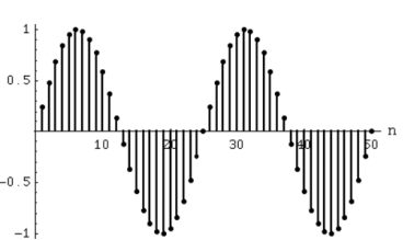
Fig:5 Discrete time signal
Even and Odd Signals
The even signals are symmetrical about Y-axis. They lie in first and second quadrants.
x[-n]=x[n]
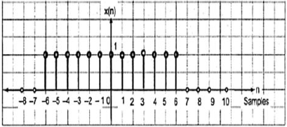
Fig:6 Even signal
The odd signals are symmetrical about origin. They lie in first and third quadrants.
x[-n]= -x[n]
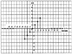
Fig:7 Odd signal
A signal having even and odd parts is mixed signal.
Periodic and Non-periodic signals:
A signal which repeats itself after a particular period of time is called as Periodic signal. The condition for any signal to be periodic is
x(n+N) = x(n)
Considering a cosine signal −
x(n)=A cos(2πf0n+θ) x(n)= A cos(2πf0n+θ)
x (n +N) = A cos (2πf0(n +N) +θ)
=A cos(2πf0n+2πf0N+θ) x (n+ N)
=A cos (2πf0(n +N) +θ) =A cos(2πf0n+2πf0N+θ)
=A cos(2πf0n+2πf0N+θ) = A cos(2πf0n+2πf0N+θ)
For the signal to become periodic, following condition should be satisfied;
X (n+ N) = x(n) x (n +N) = x(n)
A cos(2πf0n+2πf0N+θ) =A cos(2πf0n+θ)
A cos(2πf0n+2πf0N+θ) = A cos (2πf0n+ θ)
As, 2πf0N is an integral multiple of 2π
2πf0N=2πK
N=Kf0
Frequencies of discrete sinusoidal signals are separated by integral multiple of 2π.
Energy and Power Signals
Energy Signal
Energy of a discrete time signal is denoted as E. It can be written as
E = 
If each individual values of x(n)x(n) are squared and added, we get the energy signal. Here x(n) is the energy signal and its energy is finite over time i.e 0<E<∞
Power Signal
Average power of a discrete signal is represented as P. This can be written as
P = 

Key takeaway
E = 
P = 

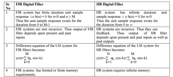
The basic realization techniques used for filters are direct form, cascade form and parallel form. In this section we will study all in detail. This section overviews ability to implement finite impulse response (FIR) and infinite impulse response (IIR) filters using different structures in terms of block diagram and signal flow graph.
For an LTI system the transfer function is given as
H(z)=  (1)
(1)
The difference equation can be written as
 (2)
(2)
x(n)= system input
y(n)=system output
When a0≠ (3)
(3)
The above equation implementation requires some basic blocks shown below
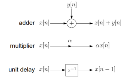
Fig 8 Block diagram representation
The above blocks can be easily understood with the help of one example. For the standard LTI system with difference equation
Y[n]=-a1y[n-1]-a2y[n-2]+b0x[n]. Draw the block diagram for the given equation.
Sol: We already know that x[n] and y[n] are the input and output to the system respectively.
- If we need the term y[n-1] we need a delay block after y[n], and one more delay block after y[n-1] to get y[n-2].
- For getting term -a1y[n-1] we need multiplier of -a1and same for -a2.
- To get complete term -a1y[n-1]-a2y[n-2]+b0x[n] we need adders so that the we get the final equation.
- The final figure using 2 adders, 3 multipliers and 2 delay block is shown below.
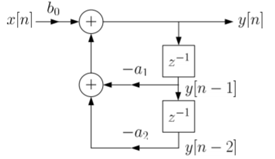
Fig 9: Block diagram representation
FIR FILTER:
The standard equation for representing the FIR filter is shown below
H(z)= (4)
(4)
From equation (1) and (4) we can conclude that FIR filters do not contain any pole. The difference equation will be
Y[n]=  (5)
(5)
a) Direct Form:
The direct form is directly derived from the difference equation. It can be represented as
y[n]=  (6)
(6)
Where h(k) is the system impulse response.
Expanding the above equation, we get
Y[n]= =h[0]x[n]+h[1]x[n-1]+……h[M]x[n-M] (7)
The block diagram representation for above direct form is shown below.

Fig 10: Direct form realization of Fir filter
b) Cascade Form:
As we already know H(z)=
The above equation can be represented as a product of second order polynomial as
H(z)= =
= (8)
(8)
Mc=|(M+1)/2|
The above equation can be further simplified with intermediate output of system 1 w1(n) fed to the input of second cascade structure and so on.
The difference equation is given as
w1(n)=  +
+ (9)
(9)
w2(n)=  +
+ (10)
(10)

Fig 11: Cascade form FIR filter
IIR FILTER:
The transfer function of IIR filter is given as
H(z)=  (11)
(11)
From above equation we can conclude that an IIR filter contains at least one pole.
a) Direct Form:
The direct form is realised directly from its difference equation
v[n]=  (12)
(12)
y[n]=-  +v[n] (13)
Another way to obtain direct form is by decomposing H(z) into two transfer functions
H(z)=H1(Z). H2(z)
H1(Z)=  (14)
(14)
H2(z)=  (15)
(15)
V(z)=X(z). H1(Z)=X(z) (16)
(16)
Y(z)=V(z). H2(z)=V(z) (17)
(17)
The final realisation block diagram representation of direct form for IIR filter is shown below
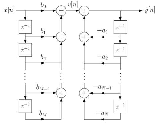
Fig 12: Direct Form realization of IIR Filter
b) Cascade form:
To find the transfer function for cascade for we need to factorize the numerator and denominator polynomials in terms of second order polynomial.
H(z)= =
= (18)
(18)
Nc=|(N+1)/2|
Let us consider M=N=4. Then the cascade realisation for IIR filter is shown below.
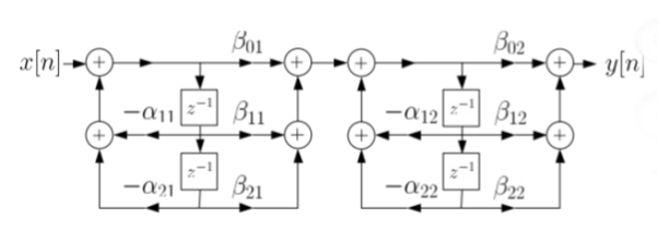
Fig 13: Cascade Form realisation of IIR Filter
Que) For the following LTI system H(z)= . Realise the cascade form IIR filter.
Sol: H(z)=
The above function can be simplified as
H(z)=
Hence, using the above structure and placing the values of 
 …. And similarly,
c) Parallel form:
The parallel form is given as H(z)= +
+
 (19)
(19)
Nc=(N=2)/2
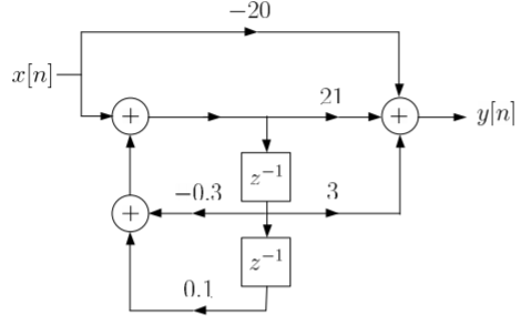
Que) Draw block diagram for the function using parallel form H(z)=
Sol: H(z)=
Writing above transfer function in standard form for parallel realisation we get
H(z)=-20+
The structure is shown below
Key takeaway
Frequency Response of LTI systems
Suppose our input signal is x(t)
X(t) = A ei2πfot + iɸ--------------------------------------(1)
Where A is the real valued amplitude, fo is the frequency and ɸ is the phase parameter.
The output y(t) =  h(t-u) du ----------------------------(2)
=  h(u) du -------------------------------------------(3)
Suppose x(t) is sine wave then
y(t) =  e i2πfo(t-u) +iɸ h(u) du ---------------------------------------------(4)
The Fourier transform of h(t) to obtain the input output relationship
y(t) = H(fo) [ A ei2πfot+iɸ]
Or
y(t) = H(fo) x(t)
The LTI system passes sine wave input to the output after scaling it by complex number H(fo) where fo is the frequency of the sine wave and H(f) is the Fourier transform of the impulse response. Linear systems do not create new frequency components they can only scale each frequency component at the input to produce the output.
The Z transform for discrete time system x(n ) is defined as
X(z) =  ------- (1) where z is a complex variable.
In polar form z can be expressed as
z = r e jw ---------------(2) where r is the radius of a circle.
For n≥ 0
X(z ) =  --------- (3)which is called one-sided z-transform.
By substituting z = r e jw
X(r e jw) =  (r e jw) –n ------- (4)
 e- jwn ----- (5)
Equation(5) represents the Fourier transform of the signal x(n) r-n
Hence the inverse DTFT X(r ejw) must be x(n) r-n.
x(n) r-n = 1/2π  r e jw ) e jwn dw
On multiplying both sides by rn we get
x(n) = 1/ 2 π  r ejw) (r ejw ) n dw [ z = r ejw
Let z= r e jw and dw= dz/jz
Dz = r ejw dw
Dw = dz/jre jw

Example
Find the z-transform for the sequence
x[n] = 2  + 3
+ 3  + 5
+ 5  + 2
+ 2 
Solution:
X(z) = 2 + 3 z-1 + 5 z -2 + 2 z -3
Example
If X(z)= 4 – 5 z-2 + z-3 – 2z -4 then find x[n]
Solution:
x[n] = 4  - 5
- 5  +
+  - 2
- 2 
Key Takeaways:
The Z transform is the discrete time analog of the Laplace transform
Properties of Z transform
Linearity
If X1(z) = Z{x1(n)} and X2(z) = Z{x2(n)}
Then
Z{ax1(n) + bx2(n)} = a X1(z) + b X2(z)
Proof:
Z{ax1(n) + b x2(n) }=  z-n
z-n
= a  z-n + b
  z-n
z-n
= a X1(z) + b X2(z)
Time Shifting
If X(z) = Z{x(n)} and initial conditions for x(n) are zero then
Z{x(n-m) } = z-m X(z)
Where m is a positive integer.
Proof:
Z {x(n-m)} =  z-n
z-n
Let n-m = p then n= p+m
Z{x(n-m)} =  z –(m+p)
z-m  z-p = z-m X(z)
Multiplication by exponential sequence
If X(z ) = Z{x(n)} then
Z [ an x(n) ] = X(a-1 z)
Proof:
Z{ an x(n) } =  an z-n
=  (az-1)n
= X(az-1)
Convolution
We know that
Z{x(n) * h(n) } = X(z) H(z)
Proof:
Let y(n) = x(n) * h(n)
y(n)= 
Taking z-transform on both sides we obtain
Y(z) =
 z-n
z-n
 z-k
z-k  z –(n-k) Replacing n-k by l
 z-k
z-k  z-l
z-l
= X(k) Z(k)
Time Reversal
If X(z) = Z{x(n)} then
Z{x(-n)} = X(z-1}
Proof:
Z{x(-n)} =  ( z-l) -1 l=-n
= X(z-1)
Multiplication by n
If Z{x(n)} = X(z) then
Z{n x(n)} = -z d/dz X(z)
X(z) = 
Z{n x(n)} = 
= z  -1
-1
= z 
= -z  }
}
= -z d/dz { 
= -z d/dz X(z)
Problems:
- Find the z-transform of the sequence
x(n) = a n-1 u(n-1)
We know that x(n) = an u(n) is
X(z) = 1/1/az-1
By using time shifting property we have Z{ x(n-k)} = z-k X(z)
Therefore
Z{an-1 u(n-1)} = z-1/ 1-az-1 = 1/z-a. ROC |z| > |a|
2. Find the z-transform of the sequence
x(n) = an cos nπ/2
Z{ cos w0n} = 1- (cos w0) z-1/ 1 –(2 cos w0) z-1 + z-2
Since w0=π/2
Z{ cos π/2 n u(n)} = 1/1 + z-2
Using exponential sequence property
Z{ an x(n) } = X(a-1 z)
Z{ an cos nπ/2} = 1/1+(a-1z)-2 = 1/ 1 + a2/z2 = z2/ a2 + z2
3. Find the z transform of the sequence x(n) = n u(n)
The z-transform of unit step sequence is given by
Z{u(n)} = z/z-1
Z{ n u(n)} = -z d/dz (z/z-1)
= z/(z-1)2
4. If x(n) = x1(n) * x2(n) where x1(n) = (1/3)n u(n) and x2(n) = (1/5)n u(n). Find X(z) by using convolution property.
X1(z) = 1/ 1- (1/3)z-1 X2(z) = 1/1- (1/5) z-1
X(z) = 1/1-(1/3)z-1 . 1/1-(1/5) z-1
Using z-transform find the convolution of two sequences.
x1(n) = {1,2,-1,0,3} x2(n) = { 1,2,-1}
Z{ x1(n) * x2(n)} = X1(z) . X2(z)
X1(z) = 1 + 2z-1 – z-2 + 3 z-4
X2(z) = 1 + 2z-1 – z-2
(1 + 2z-1 – z-2 + 3 z-4 ) (1 + 2z-1 – z-2 )
= 1 + 4z-1 + 2z-2 – 4 z- 3 + 4 z-4 + 6 z- 5 – 3 z-6
5. Determine the z-transform of the signal
x(n ) = rn (sin w0n ) u(n)
Z{(sin w0n ) u(n)} = sin w0 z-1/ 1 -2 (cos w0) z-1 + z-2
Z{ an x(n)} = X(a-1 z)
Therefore
Z{ rn sin(w0n) u(n) } = (sin w0) (r-1 z)-1/ 1- 2 (cos w0)(r-1z)-1 + (r-1z)-2
= r(sinw0) z-1/ 1-2r(cos w0) z-1 + r2 z-2
6. Determine the signal x(n) whose z-transform is given by
X(z) = log(1- az-1).
X(z)= log(1-az-1)
Differentiating both sides we get
d/dz X(z) = 1/1-az-1 (a z-2) = az-2/1- az-1
-z d/dz { X(z)} = -az-1/1-az-1
= -az-1[ 1/1-az-1]
= -a Z[ a n-1 u(n-1)] -------- (1)
From differentiation property
Z{ n x(n)} = -z d/dz [ X(z)] ------- (2)
Comparing (1) and (2) we get
n x(n) = -a [ a n-1 u(n-1)]
Or x(n) = -a [a n-1 u(n-1)]/n
7. Determine the z-transform of the signal
x(n) =1/2 (n2 + n) (1/3) n-1 u(n-1)
=½ n2 (1/3) n-1 u(n-1) +1/2 n (1/3) n-1 u(n-1)
We know that
Z[(1/3) n u(n)] = z/ z-1/3
Using time-shifting property
Z{(1/3) n-1 u(n-1)] = 1/ z- 1/3
Z [ n (1/3) n-1 u(n-1)] = -z d/dz [1/z-(1/3)]
=-z d/dz( 1/z-1/3)= -z [-1/(z-1/3) 2]= z/ (z-1/3)2
Z [ n2 (1/3) u(n-1)] = -z d/dz [ z/(z-1/3)2]
= z(z+1/3)/(z-1/3)2
= -z [ (z-1/3)2 -2z(z-1/3)/(z-1/3)4
= z(z+1/3)/(z-1/3)3
X(z) = ½[z(z+1/3)/(z-1/3)3 + z/ (z-1/3)2]
= z2/(z-1/3)3
8. Find the z-transform and ROC of the signal
x(n) = an u(n)
Solution:
X(z) = 
=  an u(n) -----(1) u(n) = 0 for n<0
1 for n≥0
=  an ------- (2)
=  n ------- (3)
This is a geometric series of infinite length that is
a + ar + ar2 + ………….. ∞ = a /1-r if |r| <1
Then from equation (3) it converges when |az-1| < 1 or |z| >|a|
Therefore
X(z) = 1/ 1-az-1: ROC |z| > |a|
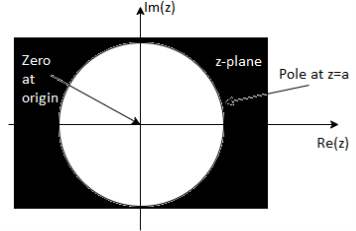
9. Find the z-transform of the signal x(n) =-b n u(-n-1). Find ROC
X(z) = 
X(z) =  bn u(-n-1) u(-n-1) =0 for n ≥0
= 1 for n ≤ -1
=  bn =
bn =  b-1 =
b-1 =
= b-1z/1- b-1z = z/ z-b = 1/ 1-bz-1 |z| < |b|
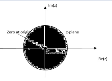
10. Find the z-transform of x(n) = an u(n) – bn u(-n-1)
X(z) = 
=  n +
n +  b-1
b-1
= z/z-a + z/z-b ROC |a| < |z| < |b|
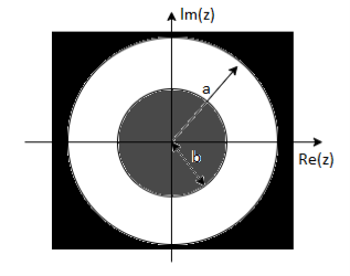
|b|< |a|
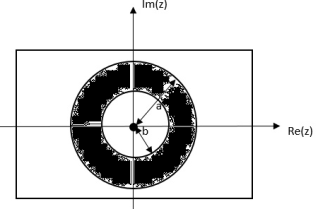
|b| >|a|
11. Find the z-transform of x(n) = {1,2,3,2}
Given x(0) = 1 x(1) =2 x(2) =3 x(3) = 2
X(z) = 
X(z) = 1+ 2z-1 + 3 z-2 +2 z-3
We know that
Z{x(n) * h(n) } = X(z) H(z)
Proof:
Let y(n) = x(n) * h(n)
y(n)= 
Taking z-transform on both sides we obtain
Y(z) =
 z-n
z-n
 z-k
z-k  z –(n-k) Replacing n-k by l
 z-k
z-k  z-l
z-l
= X(k) Z(k)
The covariance has units (units of X times units of Y), and thus it can be difficult to assess how strongly related two quantities are. The correlation coefficient is a dimensionless quantity that helps to assess this.
The correlation coefficient between X and Y normalizes the covariance such that the resulting statistic lies between -1 and 1. The Pearson correlation coefficient
Is 
The correlation matrix for X and Y is

References:
1. Ifeachor E.C, Jervis B. W, “Digital Signal Processing: Practical approach”, Pearson Publication, 2nd Edition.
2. Li Tan, “Digital Signal Processing: Fundamentals and Applications”, Academic Press, 3rd Edition.
3. Schaum's Outline of “Theory and Problems of Digital Signal Processing”, 2nd Edition.
4. Oppenheim, Schafer, “Discrete-time Signal Processing”, Pearson Education, 1st Edition.
5. K.A. Navas, R. Jayadevan, “Lab Primer through MATLAB”, PHI, Eastern Economy Edition.