Unit – 3
8051 Serial Communication
- 8051 provides a transmit channel and a receive channel of serial communication. The transmit data pin (TXD) is specified at P3.1, and receive data pin (RXD) at P3.0.
- The serial signals provided on these pins are TTL signal levels and must be boosted and inverted through a suitable converter to comply with RS232 standard.
- All modes are controlled through SCON(Serial Control Register). The timers are controlled using TMOD (Timer Mode register) and TCON(Timer Control register)
SCON register:
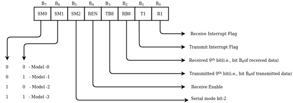
SCON – Serial Port Control Register
SM0 – Serial port mode 0 shift register
SM1 – serial port mode 1 8-bit UAR + variable
SM2 – enable multiprocessor communication in mode 2/3
REN – set/clear by software to enable/disable reception.
TB8 – the 9th bit will be transmitted in mode 2/3 set/clear by software
RB8 – In mode 2/3 it is the 9th bit that was received in mode 1 if SM2 = 0, RB8 is the stop bit that was received in mode which is not used.
TI – transmit interrupt flag set by hardware at the end of 8-bit in mode 0 at the beginning of the stop bit. In the other mode it must be cleared by software.
RI – receive interrupt flag set by hardware and must be cleared by software.
TMOD register
TMOD is an 8-bit register for selecting timer or counter and mode of timers. The lower 4-bits are used for control operation of timer 0 or counter0. The remaining 4-bits for control operation of timer1 or counter1.This register is present in SFR register and the address for SFR register is 89th.
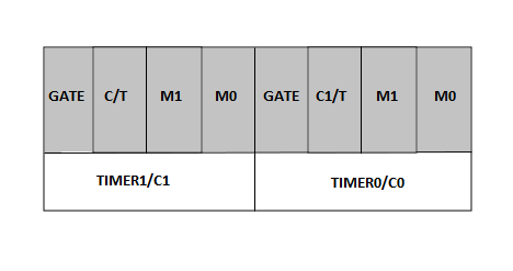
Timer Mode Control
Gate: If the gate bit is set to ‘0’, then we can start and stop the “software” timer in the same way. If the gate is set to ‘1’, then we can perform hardware timer.
C/T: If the C/T bit is ‘1’, then it is acting as a counter mode, and similarly when set C+
=/T bit is ‘0’; it is acting as a timer mode.
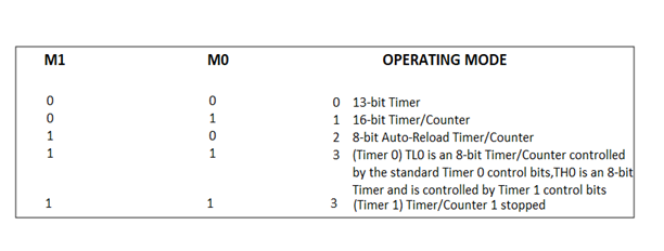
Mode select bits: The M1 and M0 are mode select bits, which are used to select the timer operations. There are four modes to operate the timers.
Mode 0: This is a 13-bit mode that means the timer operation completes with “8192” pulses.
Mode 1: This is a16-bit mode, which means the timer operation completes with maximum clock pulses that “65535”.
Mode 2: This mode is an 8-bit auto reload mode, which means the timer operation completes with only “256” clock pulses.
Mode 3: This mode is a split-timer mode, which means the loading values in T0 and automatically starts the T1.
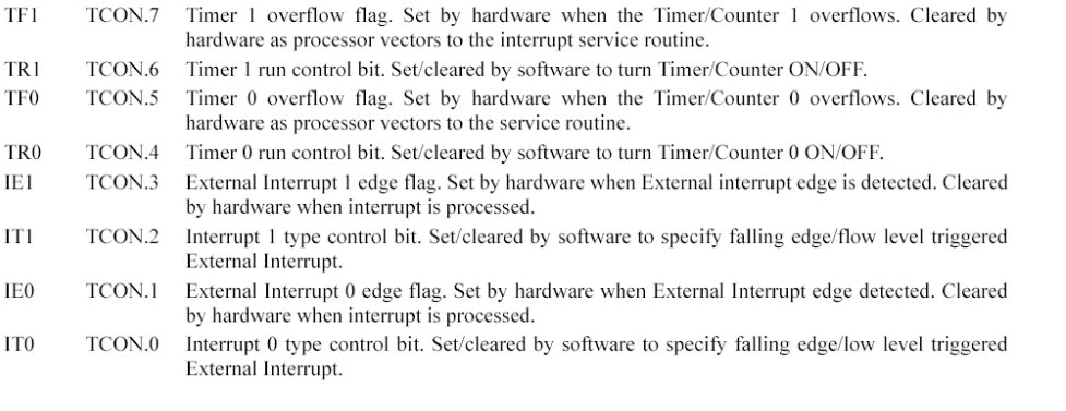
TCON register:

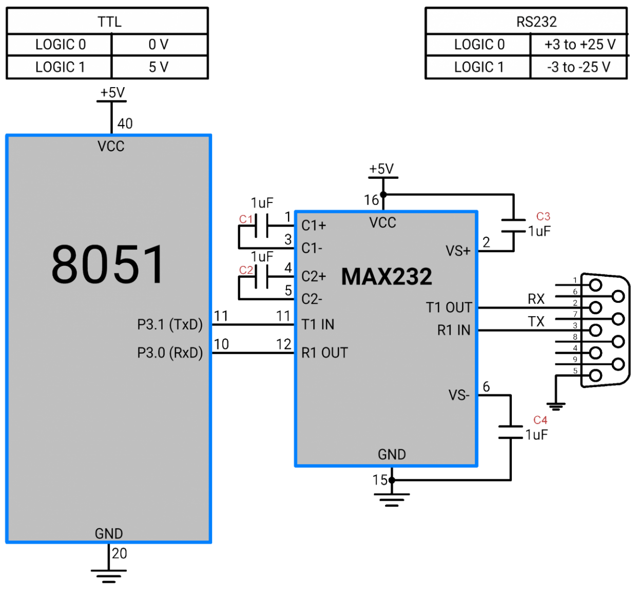
Since IBM PC/compatible computers are so widely used to communicate with 8051-based systems, serial communications of the 8051 with the COM port of the PC will be emphasized.
To allow data transfer between the PC and an 8051 system without any error, we must make sure that the baud rate of the 8051 system matches the baud rate of the PC‟s COM port.
Baud rate in the 8051
The 8051 transfers and receives data serially at many different baud rates. Serial communications of the 8051 is established with PC through the COM port. It must make sure that the baud rate of the 8051 system matches the baud rate of the PC's COM port/ any system to be interfaced. The baud rate in the 8051 is programmable. This is done with the help of Timer.
When used for serial port, the frequency of timer tick is determined by (XTAL/12)/32 and 1 bit is transmitted for each timer period. The Relationship between the crystal frequency and the baud rate in the 8051 is that the 8051 divides the crystal frequency by 12 to get the machine cycle frequency which is shown in figure.

Figure. Oscillatory Frequency
Here the oscillator is XTAL = 11.0592 MHz, the machine cycle frequency is 921.6 kHz. 8051's UART divides the machine cycle frequency of 921.6 kHz by 32 once more before it is used by Timer 1 to set the baud rate. 921.6 kHz divided by 32 gives 28,800 Hz. Timer 1 must be programmed in mode 2, that is 8-bit, auto-reload.
Calculation of baud rate:
In serial communication if data transferred with a baud rate of 9600 and XTAL used is 11.0592 then following is the steps followed to find the TH1 value to be loaded.
Clock frequency of timer clock: f = (11.0592 MHz / 12)/32 = 28,800Hz.
Time period of each clock tick: T0 = 1/f = 1/28800
Duration of timer: n*T0 (n is the number of clock ticks) 9600 baud ->duration of 1 symbol:
1/9600 1/9600 = n*T0 = n*1/28800 n = f/9600 = 28800/9600 = 3 ->TH1 =-3
Similarly, for baud 2400 n = f/2400 = 12 ->TH1 = -12
Example:
Set baud rate at 9600
MOV TMOD, #20H; timer 1, mode 2(auto reload)
MOV TH1, #-3; To set 9600 baud rate
SETB TR; start timer 1
Steps to send data serially:
1.Set baud rate by loading TMOD register with the value 20H, this indicating timer 1 in mode 2 (8-bit auto-reload) to set baud rate
2. The TH1 is loaded with proper values to set baud rate for serial data transfer
3. The SCON register is loaded with the value 50H, indicating serial mode 1, where an 8- bit data is framed with start and stop bits
4. TR1 is set to 1 to start timer 1
5. TI is cleared by CLR TI instruction
6. The character byte to be transferred serially is written into SBUF register
7. The TI flag bit is monitored with the use of instruction JNB TI, xx to see if the character has been transferred completely
8. To transfer the next byte, go to step 5
Program to transfer letter “D” serially at 9800baud, continuously
MOV TMOD, #20H; timer 1, mode 2(auto reload)
MOV TH1, #-3; 9600 baud rate
MOV SCON, #50H; 8-bit, 1 stop,
REN enabled
SETB TR1; start timer 1
AGAIN: MOV SBUF, #”D”; letter “D” to transfer
HERE: JNB TI, HERE; wait for the last bit
CLR TI; clear TI for next char
SJMP AGAIN; keep sending A
Steps to receive data serially:
1. Set baud rate by loading TMOD register with the value 20H, this indicating timer 1 in mode 2 (8-bit auto-reload) to set baud rate
2. The TH1 is loaded with proper values to set baud rate
3. The SCON register is loaded with the value 50H, indicating serial mode 1, where an 8- bit data is framed with start and stop bits
4. TR1 is set to 1 to start timer 1
5. RI is cleared by CLR RI instruction
6. The RI flag bit is monitored with the use of instruction JNB RI, xx to see if an entire character has been received yet
7. When RI is raised, SBUF has the byte; its contents are moved into a safe place
8. To receive next character, go to step 5
Program to receive bytes of data serially, and put them in P2, set the baud rate at 9600, 8-bit data, and 1 stop bit:
MOV TMOD, #20H; timer 1, mode 2(auto reload)
MOV TH1, #-3; 9600 baud rate MOV SCON, #50H; 8-bit, 1 stop,
REN enabled SETB TR1; start timer 1
HERE: JNB RI, HERE; wait for char to come in
MOV A, SBUF; saving incoming byte in A
MOV P2, A; send to port 1
CLR RI; get ready to receive next byte
SJMP HERE; keep getting data
After 'RESET' all the interrupts get disabled, and therefore, all the interrupts are enabled by software. From all the five interrupts, if anyone or all interrupt are activated, this will set the corresponding interrupt flags as represent in the figure which corresponds to Interrupt structure of 8051 microcontroller:
Interrupts in 8051 Microcontroller
All the interrupts can be set or cleared by some special function register that is also known as interrupt enabled (IE), and it is totally depends on the priority, which is executed by using interrupt priority register.
Interrupt Enable (IE) Register
IE register is used for enabling and disabling the interrupt. This is a bit addressable register in which EA value must be set to one for enabling interrupts. The individual bits in this register enables the particular interrupt like timer, serial and external inputs. Consider in the below IE register, bit corresponds to 1 activate the interrupt and 0 disable the interrupt.
Interrupt Priority Register (IP)
Using IP register, it is possible to change the priority levels of an interrupts by clearing or setting the individual bit in the Interrupt priority (IP) register as shown in figure. It allows the low priority interrupt can interrupt the high-priority interrupt, but it prohibits the interruption by using another low-priority interrupt. If the priorities of interrupt are not programmed, then microcontroller executes the instruction in a predefined manner and its order are INT0, TF0, INT1, TF1, and SI.
Interrupt programming in 8051
Timer Interrupt Programming: In microcontroller Timer 1 and Timer 0 interrupts are generated by time register bits TF0 AND TF1. This timer interrupts programming by C code involves:
Selecting the configuration of TMOD register and their mode of operation.
Enables the IE registers and corresponding timer bits in it.
Choose and load the initial values of TLx and THx by using appropriate mode of operation.
Set the timer run bit for starting the timer.
Write the subroutine for a timer and clears the value of TRx at the end of the subroutine.
Let's see the timer interrupt programming using Timer0 model for blinking LED using interrupt method:
#include< reg51 .h>
Sbit Blink Led = P2^0; // LED is connected to port 2 Zeroth pin
Void timer0_ISR (void) interrupt 1 //interrupt no. 1 for Timer0
{
Blink Led=~Blink Led; // Blink LED on interrupt
TH0=0xFC; // loading initial values to timer
TL0=0x66;
}
Void main()
{
TMOD=0x0l; // mode 1 of Timer0
TH0 = 0xFC: // initial value is loaded to timer
TL0 = 0x66:
ET0 =1; // enable timer 0 interrupt
TR0 = 1; // start timer
While (1); // do nothing
}
External Hardware Interrupt Programming
Microcontroller 8051 is consisting of two external hardware interrupts: INT0 and INT1 as discussed above. These interrupts are enabled at pin 3.2 and pin 3.3. It can be level triggered or edge triggered. In level triggering, low signal at pin 3.2 enables the interrupt, while at pin 3.2 high to low transition enables the edge triggered interrupt.
Enables the equivalent bit of external interrupt in Interrupt Enable (IE) register.
If it is level triggering, then write subroutine appropriate to this interrupt, or else enable the bit in TCON register corresponding to the edge triggered interrupt.
Consider the edge triggered external hardware interrupt programming is:
Void main()
{
IT0 = 1; // Configure interrupt 0 for falling edge on INT0
EXO = 1; // Enabling the EX0 interrupt
EA =1; // Enabling the global interrupt flag
}
Void ISR_ex0(void) interrupt 0
{
<body of interrupt>
}
Serial Communication Interrupt Programming
It is used when there is a need to send or receive data. Since one interrupt bit is used for both Transfer Interrupt (TI) and Receiver Interrupt (RI) flags, Interrupt Service Routine (ISR) must examine these flags for knowing the actual interrupt. By the logical OR operation of RI and TI flags causes the interrupt and it is clear by the software alone. Consider the steps involved in serial communication interrupt programming are:
Configure the Interrupt Enable register for enabling serial interrupt.
Configure the SCON register for performing transferring and receiving operation.
Write a subroutine for given interrupt with appropriate function.
Program for sending 'E' through serial port with 9600 baud rate using Serial Interrupt:
Void main()
{
TMOD = 0x20:
TH1= 0xFD; // baud rate for 9600 bps
SCON = 0x50;
TR1=1;
EA=l;
While(l);
}
Void ISR_Serial(void) interrupt 4
{
If (TI==l)
{
SBUF=? E?;
TI=0;
}
Else
RI =0;
}
References:
- Microprocessor Architecture, Programming, and ...Book by Ramesh S. Gaonkar
- 8085 Microprocessor: Programming and Interfacing Book by N. K. Srinath
- 8085 Microprocessors & Its Application Book by Nagoorkani
- C and the 8051: Building efficient applications Book by Thomas W. Schultz
- MICROCONTROLLER Book by V. Udayashankara