Unit - 5
Basic concept of PIC microcontroller
Features
- This has high performance RISC CPU.
- 40-pin PDIP, high performance, enhanced Flash Microcontroller with CAN.
- The Operating speed ranges between 40 MHz up to 10 MIPS.
- The Operating voltage ranges 4.2 to 5.5 V
- ROM of size 2M bytes
- RAM between 256 bytes to 4096 bytes.
- On-chip program ROM in form of flash memory.
- Data EEPROM
- 8 x 8 Single cycle Hardware Multiplier
- 16-bit wide instructions, 8-bit wide data path.
- 75 instructions.
- ADC and USART PROTOCOL for PC communication.
- I/O port between 16 to 72 pins and I/O port register are bit and port accessible.
- SPI PROTOCOL and I2C PROTOCOL for memory communication.
- PIC 18F458 has two-stage pipeline.
- Interrupt capability with Priority levels.
- Linear program memory addressing upto 2 Mbytes
Selection:
- Speed
- Amount of RAM/ROM
- Numbers of I/O pins, Timers
- Power Consumption
- Tools of availability
- Added features like ADC/DAC/CCP, Bus support like CAN, SPI, I2C, USB.
- Watch Dog timer, Timer modes, Data EEPROM.
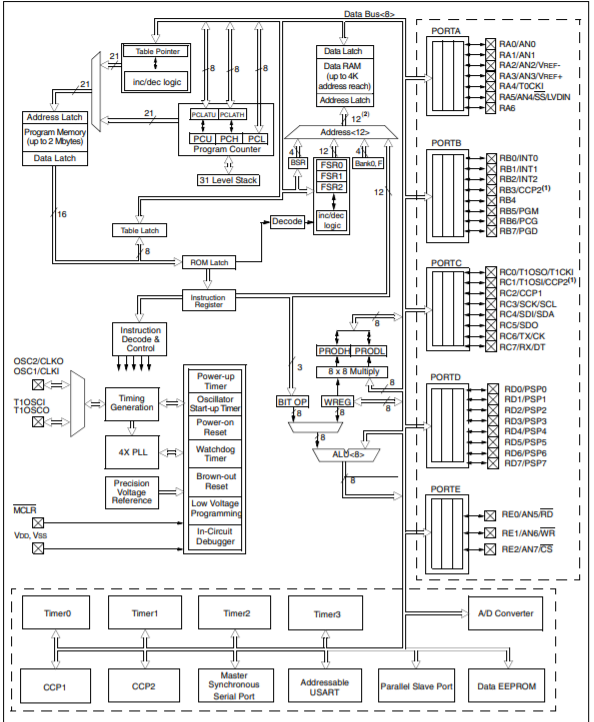
Figure 1. Architecture of PIC controller
The microcontroller architecture consists of CPU, I/O ports, memory organization, A/D converter, timers/counters, interrupts, serial communication, oscillator and CCP module
CPU (Central Processing Unit)
The PIC microcontroller CPU consists of the Arithmetic and Logic Unit, Memory Unit, Control Unit, accumulator and so on.
Arithmetic logic unit are mainly used for arithmetic operations and logical decisions. After processing, for storing the instructions memory is used. To control the internal and external peripherals, control unit is used to connect to CPU and accumulator is used for storing results.
Memory Organization
The memory module consists of RAM, ROM and STACK.
Random Access Memory (RAM)
RAM is an unstable memory used to store data temporarily in its registers. The registers of RAM are classified into Special Function Registers (SFR) and General-Purpose Registers (GPR).
General Purpose Registers (GPR)
These registers are used for general purpose only.
Special Function Registers
They are mainly used for special purposes only. These registers perform according to the functions assigned to them,
The STATUS register cannot be used for storing data, these registers are used for showing the operation or status of the program.
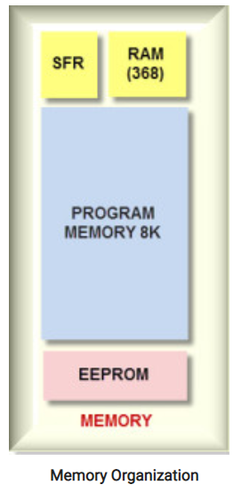
Figure 2. Memory Organization
Read Only Memory (ROM)
Read only memory is a stable memory used to store the data permanently. In PIC microcontroller ROM stores the instructions or programs. The microcontroller acts according to the program.
The ROM is also called as program memory, here the user writes the program and saves it permanently and executed by CPU. The microcontroller’s performance depends on the instruction executed by the CPU.
Electrically Erasable Programmable Read Only Memory (EEPROM)
Normally in ROM, we write the program only once and cannot use it multiple times. But, in EEPROM you can program the ROM multiple times.
Flash Memory
Flash memory also known as programmable read only memory (PROM) can read, write and erase the program thousands of times. PIC microcontroller uses this type of ROM.
Stack
When an interrupt occurs, first the PIC microcontroller must execute the interrupt and the existing process address that is being executed and store it in the stack. After completing the execution of the interrupt, the microcontroller calls the process with the help of address, which is stored in the stack and executes the process.
BUS
BUS is used for transfer and receive of data from one peripheral to another. It is classified into two types that is address and data bus.
Data Bus: It is used to transfer or receive the data.
Address Bus: Address bus transmits the memory address from peripherals to CPU. I/O pins are used to interface with external peripheral. UART and USART are serial communication protocols used for interfacing serial devices like GSM, GPS, Bluetooth, IR, and so on.
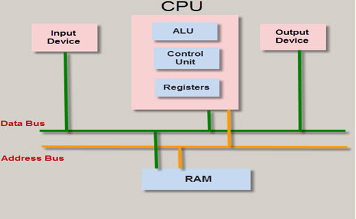
Figure 3. BUS
A/D converters
The analog to digital converter converts analog voltage values to digital voltage values. A/D module of PIC microcontroller consists of 5 inputs of 28 pin devices and 8 inputs of 40 pin devices.
The operation of the analog to digital converter is controlled by special registers ADCON0 and ADCON1. The upper bits of the converter are stored in ADRESH register and lower bits of the converter are stored in ADRESL register. It requires 5V of an analog reference voltage for operation.
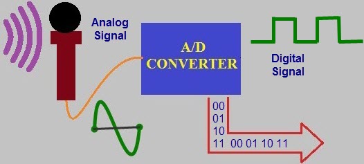
Figure 4. A/D CONVERTER
Timers/ Counters
PIC microcontroller consists of four timer/counters wherein one is 8-bit timer and the remaining timers can be 8 or 16-bit mode. Timers are used for generating accuracy actions, for example, creating specific time delays between two operations.
Interrupts
PIC microcontroller consists of 20 internal interrupts and three external interrupt sources associated with different peripherals like ADC, USART, Timers, and so on.
Serial Communication
Serial communication is the method used for transferring data one bit at a time sequentially over communication channel.
- USART: (Universal synchronous and Asynchronous Receiver and Transmitter)
The two serial communication protocols used for transmitting and receiving data bit by bit over a single wire with respect to clock pulses. The PIC microcontroller has two pins TXD and RXD used for transmitting and receiving the data serially.
- SPI Protocol: (Serial Peripheral Interface)
This protocol is used for sending data between PIC microcontroller and other peripherals which include SD cards, sensors and shift registers.
PIC microcontroller supports three- wire SPI communications between two devices on a common clock source.
I2C Protocol: (Inter Integrated circuit)
A serial protocol used to connect low speed devices such as EEPROMS, microcontrollers, A/D converters, and so on. PIC microcontroller support two wire Interface or I2C communication between two devices which can work as Master and Slave device.
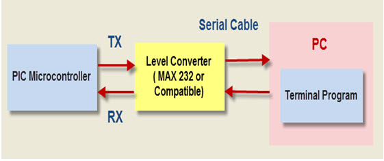
Figure 5. Serial Communication
CCP module
CCP module stands for capture/compare/PWM.
- Capture Mode: Capture mode captures the time of arrival of a signal, that is when the CCP pin goes high, it captures the value of Timer1.
- Compare Mode: Compare mode acts as analog comparator. When timer1 value reaches certain reference value it generates output.
- PWM Mode: PWM mode provides pulse width modulated output with 10-bit resolution and programmable duty cycle.
Family Offering (Pin Count vs. Memory)
Flash (KB) | 8 Pins | 14 Pins | 20 Pins | 28 Pins | 40 Pins |
28 |
|
|
| PIC16F15256 | PIC16F15276 |
14 |
| PIC16F15225 | PIC16F15245 | PIC16F15255 | PIC16F15275 |
7 | PIC16F15214 | PIC16F15224 | PIC16F15244 | PIC16F15254 | PIC16F15274 |
3.5 | PIC16F15213 | PIC16F15223 | PIC16F15243 |
|
|
Key Features
- Up to 2 KB SRAM
- Up to 28-channel, 10-bit differential Analog-to-Digital Converter (ADC)
- Two Capture/Compare/PWMs (CCPs)
- Two 10-bit PWMs
- Two 16-bit timers with gate control
- One 8-bit timer with a Hardware Limit Timer (HLT)
References:
- Microprocessor Architecture, Programming, and ...Book by Ramesh S. Gaonkar
- 8085 Microprocessor: Programming and Interfacing Book by N. K. Srinath
- 8085 Microprocessors & Its Application Book by Nagoorkani
- C and the 8051: Building efficient applications Book by Thomas W. Schultz
- MICROCONTROLLER Book by V. Udayashankara