Unit - 4
The Energy Equation and its Application
Introduction:
Kinematics is described as the discipline of science that studies particle motion without considering the factors that cause the motion. This discipline of fluid mechanics studies the velocity at any point in a flow field at any time. Once the velocity has been measured, the pressure distribution and, as a result, the forces acting on the fluid, may be calculated.
Methods of describing fluid motion:
Two methods are used to explain fluid motion. They are the Lagrangian Method and the Eulerian Method, respectively. A single fluid particle is followed during its motion in the Lagrangian approach, and its velocity, acceleration, density, and other properties are described. The velocity, acceleration, pressure, density, and other parameters are described at a point in the flow field using the Eulerian Method. In fluid mechanics, the Eulerian method is widely employed.
Langragian method
In this method, the observer concentrates on the movement of a single particle.
The path taken by the particle and the changes in its velocity and acceleration are studied.
In the cartesian system the position of the fluid particle in space (x, y, z) at any time t from its position (a, b, c) at time t=0 shall be given as,
x = f1(a, b, c, t)
y = f2(a, b, c, t)
z = f3(a, b, c, t)
The velocity and acceleration components (obtained by taking derivations with respect to time) are given by,
Velocity components:


Acceleration component:


At any point, the resultant velocity or acceleration shall be the resultant of these components of the respective quantity at that point.
Resultant velocity,

Acceleration,

Similarly, other quantities like pressure, density, etc. can be found.
Eulerian Method
In Eulerian method, the observer concentrates on a point in the fluid system. Velocity, acceleration, and other characteristics of the fluid at that point are studied.
This method is almost exclusively used a fluid mechanics, especially because of its mathematical simplicity. The velocity at any point (x, y, z) can be written as
u = f1(x, y, z, t)
v = f2(x, y, z, t)
w = f3(x, y, z, t)
The components of acceleration of the fluid particle can be worked out by partial differentiation as follows:


Now, resultant velocity:

Acceleration,

Types of fluid flow:
- Steady and Unsteady flows
Steady flow – The type of flow in which the fluid characteristics like velocity, pressure, density, etc. at a point do not change with time is called steady flow.
Example: Flow through a prismatic or non-prismatic conduct at a constant flow rate Q m3/s is steady.
Mathematically,

Unsteady flow: It is that type of flow in which the velocity, pressure or density at a point change w.r.t. Time.
E.g.: the flow in a pipe whose value is being opened or closed gradually.
Mathematically, 
- Uniform and Non-uniform Flows
Uniform flow – The type of flow, in which the velocity at any given time does not change with respect to space is called uniform flow.
E.g.: Flow through a straight prismatic conduit.
Mathematically,  when t = constant
Non-uniform flow – It is that type of flow in which the velocity at any given time changes with respect to space.
E.g.: Flow through non-prismatic conduit.
Mathematically,  when t = constant
- One, two & Three-dimensional flow
One dimensional flow – it is that type of flow in which the flow parameter such as velocity is a function of time and one space coordinate.
E.g.: Flow in a pipe where average flow parameters are considered for analysis.
Mathematically, u = f(x), v = 0 & w = 0
Two-dimensional Flow – The flow in which the velocity is a function of time, and two rectangular space coordinates is called two-dimensional flow.
E.g.: Flow between parallel plates of infinite extent.
Mathematically, u = f1(x, y) v = f2(x, y) & w = 0
Three-dimensional flow – It is that type of flow in which the velocity is a function of time and three mutually perpendicular directions.
E.g.: Flow in a converging or diverging pipe or channel.
Mathematically, u = f1(x, y, z) v = f2(x, y, z) & w = f3(x, y, z)
- Rotational and Irrotational Flows
Rotational Flow -A flow said to be rotational if the fluid particles while moving in the direction of flow rotate about their mass centres.
E.g.; Motion of liquid in a rotating tank.
Irrotational flow - A flow said to be rotational if the fluid particles while moving in the direction of flow do not rotate about their mass centres.
E.g.: Flow above a drain hole of a stationary tank or a water basin.
- Laminar and Turbulent Flows
Laminar Flow – A Laminar flow is one in which paths taken by the individual particles do not cross one another and move along well-defined path.
E.g.: Flow of blood in veins and arteries.
Turbulent Flow – A turbulent flow is that flow in which fluid particles move in a zig zag way.
E.g.: High velocity flows in conduit of large size.
- Compressible & Incompressible Flow
Compressible Flow – It is that type of Flow in Which the density ( ) of the fluid changes from point to point.
E.g.: Flow of gases through orifices, nozzles, gas turbines, etc.
Mathematically, 
Incompressible Flow – It is that type of flow in which density is constant for the fluid flow. Liquids are generally considered flowing incompressible.
E.g.: subsonic aerodynamics.
Mathematically, 
- Subcritical, Critical & Supercritical Flow
Subcritical flow– When Froude’s number is less than one the flow is known as subcritical flow.
Mathematically, Fr 
Critical flow– When Froude’s number is equal to one the flow is known as subcritical flow.
Mathematically, Fr 
Supercritical flow– When Froude’s number is more than one the flow is known as subcritical flow.
Mathematically, Fr 
Rate of flow or discharge:
It is defined as the amount of fluid flowing per second via a pipe or channel portion. The volume of fluid moving through the section per second is the rate of flow or discharge for an incompressible fluid (or liquid).
The weight of fluid moving through the section is commonly used to calculate the rate of flow for compressible fluids.


Consider a liquid flowing through a pipe in which,


Continuity equation:
Continuity equation in 1D
The continuity equation is based on the principle of conservation of mass. It states as follows
If no fluid is added or removed from the pipe in any length, then the mass passing across different sections shall be same.
Consider two cross-sections of a pipe as shown in fig.
Let, A1 & A2 = Areas of the pipe at section 1-1 & section 2-2 respectively.
V1 & V2 = Velocities of the fluid at section 1-1 & section 2-2 respectively.
 1 &
1 &  2 = Densities of the fluid at section 1-1 & section 2-2 respectively.
Total quantity of fluid passing through the section 1-1 = ρ1A1V1
Total quantity of fluid passing through the section 2-2 = ρ2A2V2
From the law of conservation of matter
ρ1 A1 V1 = ρ2 A2 V2
In case of incompressible fluids  1 =
1 = 2
2

Continuity equation in 3D flow
Considers a fluid element (control volume)- parallelepiped with sides dx, dy and dz as shown in fig.
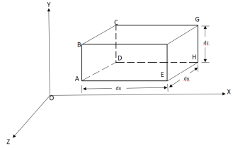
Let,  = Mass density of the fluid at a particular instant
u, v, w= components of velocity of flow entering the three faces of the parallelepiped.
Rate of Mass of fluid entering the face ABCD


Rate of Mass of fluid leaving the lace FEGH

:. Mass accelerated per unit time, due to flow in x-direction


Similarly, the gain in fluid mass per unit time in the parallelepiped due to flow in Y and Z- direction.


The total gain in fluid mass per unit for fluid along three co-ordinate axes

Rate of change of mass of the parallelepiped (control volume)

From Equation 1& 2

Simplification and rearrangement of teams would reduce the above expression to

This eq. Is the general equation of continuity in three dimension and is applicable to any type of flow and for any fluid whether compressible as incompressible
For steady flow ( =0) incompressible fluids (
 = constant) the equation reduces to

For two-dimensional flow eq. Reduce to

Velocity and Acceleration fields:
Let V is the resultant velocity at any point in a fluid flow.
Let u, v and w are its components in x, y and z directions.
The velocity components are functions of space coordinates and time. Mathematically, the velocity components are given as
u = f1(x, y, z, t)
v = f2(x, y, z, t)
w = f3(x, y, z, t)
And Resultant velocity, v = 
→ |v| = 
Let ax, ay and az are the total acceleration in x, y and z direction respectively. Then by the chain rule of differentiation, we have

But


Similarly,


Acceleration vector


Local Acceleration and Connective Acceleration
Local acceleration is defined as the rate of increase of velocity with respect to time at a given point in a flow field.
The expression  and
and  is known as local acceleration.
Connective acceleration is defined as the rate of change of velocity due to the change of position of fluid particle in a fluid flow. The expression other than  and
and  in equation are known as connective acceleration.
Velocity Potential Function:
The velocity potential is defined as scaler function of space and time such that its negative derivative with respect to any directions gives the fluid velocity in that direction.
It is denoted by Ø (phi)
Thus, mathematically the velocity potential is defined as
Ø = f (x, y, z, t)
And Ø = f (x, y, z)


Where u, v and w are the components of velocity in the x, y and z directions respectively.
The negative sign signifies that Ø decreases with an increase in the values of x, y and z. In other words, it indicates that the flow is always in the direction of decreasing Ø.
Stream function:
It is defined as the scalar function of space and time such that its partial derivative with respect to any direction gives the velocity component at right angles to that direction.
It is denoted by Ψ (psi) and defined only for two-dimensional flow.
Mathematically, for ready flow it is defined as Ψ = f (x, y) such that

And

Equipotential Line:
A line along which the velocity potential Ø is constant is called Equipotential line.


Line of constant stream function:


But,

For a line of constant stream function,


Flow Net:
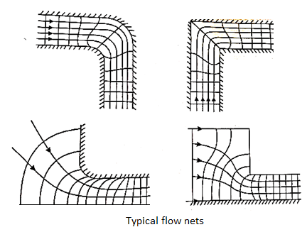
A now net is a grid created by drawing a set of equipotential lines and streamlines. In the analysis of two-dimensional irrotational flow issues, the flow net is a useful tool.
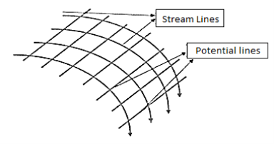
Properties of flow net
- Each flow line and an equipotential line must connect at a 90o angle, which means they must be orthogonal to one another.
- Two flow lines or two equipotential lines should never cross.
- The head loss between two neighbouring potential lines is the same.
- Flow nets are drawn only based on boundary conditions. A flow field is the space generated between two flow lines and two equipotential lines. It is independent of the permeability of the soil and the head creating flow. • Smoothly drawn curves, such as flow lines or equipotential lines, should be used.
Important Uses of flow net
- Determining the stream and equipotential lines.
- Determine the amount of seepage and the upward lift pressure beneath the hydraulic structure.
- Calculate the velocity and pressure distribution at given flow boundaries.
- To decide the outlet design to streamline them.
Methods of drawing flow nets
- Analytical method
- Here, the equations corresponding to the curves
 and
and  are first obtained and the same are plotted to give the flow net pattern for the flow of fluid between the given boundary shape.
 - This method can be applied to problem with simple and ideal boundary conditions.
2. Graphical method
- A graphical method consists of drawing streamlines and equipotential lines such that they cut orthogonally and form curvilinear squares.
- This method consumes lot of time and requires lot of erasing to get the proper shape of a flow net.
3. Electrical Analogy Method
- This method is a practical method of drawing a flow net or a particular set of boundaries.
- It is based on the fact that the flow of fluids and flow of electricity through a conductor are analogous.
- These two systems are similar in the respect that electric potential is analogous to the velocity potential, electric current is analogous to the velocity of flow and the homogenous conductor is analogous to the homogenous fluid.
4. Hydraulic Models
- Streamlines can be traced by injecting a dye in a seepage model or Heleshaw apparatus.
- Then by drawing equipotential lines, the flow net is completed.
Relation between Stream Function and Velocity Potential Function:
As,


So,


Hence,


Types of Motion:
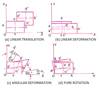
When a fluid particle moves, it can experience any or all of the four types of displacements listed below.
- Linear translation or pure translation
It is defined as the physical movement of a fluid element from one position to another.
“Two axes ab and cd represented in new positions by a'b' and c' d' are parallel.”
- Linear deformation
It is defined as the linear deformation of a fluid element when the element moves. The element's axes are parallel in the deformed and un-deformed positions, but their lengths differ.
- Angular rotation
It is defined as the average change in the angle contained by two adjacent sides.


- Rotation
The movement of a fluid element in such a way that both of its axes (horizontal and vertical rotate in the same direction is referred to as lt.


Vorticity:
The vorticity (Ω) is defined as the circulation per unit of enclosed are

If a flow possesses vorticity, it is rotational.
Rotation  is defined as one half of the vorticity.

The flow is irrational if rotation  is zero.
For three-dimensional flow


In the vector notation, the above equation can be written as

ω = (∆ ×V)
The vector ( is the curl of velocity vector.
Vorticity Ω = Curl V = (
Which may be expressed as


The vorticity components are separately given by
 = 2
= 2
 2
2

The motion is described as irrotational when the component of rotation or vorticity are zero throughout certain portion of the fluid.
Angularity:
In this type of motion, the fluid element deforms in such a way that the two axes rotate by the same amount but in opposite directions with respect to the original positions. It is defined as the average change in the angle between the two adjacent sides of a fluid element. Let δα1 be the angular displacement of x-axis and δα2 be the angular displacement of y-axis in time d t. Since δα1 is caused by the variation of v along the x-axis, we get:

Flow visualization:
Streamline:
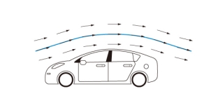
- A streamline may be defined on as an imaginary line within the flow so that the tangent at any point on it indicates the velocity at that point.
- An important concept in aerodynamics research touches on the concept of simple methods. The arrangement is the process followed by the weightless particles as they flow and flow.
- It is easier to visualize a streamline when moving through the body (unlike walking and flow).
- The integrated broadcast around the airfoil and near the cylinder. In both cases, we move with the object and the flow continues from left to right.
- As the streamline is followed by moving particles, at all points along the path the velocity is moving along the path. Since there is no standard object on the road, the magnitude cannot cross a straight line.
- The complexity contained between any two streams remains the same throughout the flow. We can use Bernoulli's figure to associate the pressure and speed associated with easy movement.
- Since there is no weight passing over the airfoil (or cylinder), the surface of the object is the easiest way.
- The planes fly through almost dry air, but we build and test them using air channels, where the model of the plane is stopped, and the wind is blown through that model.
- The idea of keeping the airfoil fixed and that the airflow passing through the airfoil can be a little confusing. However, you experience the same kind of thing every day
- If you stand on a corner and watch the car pass by, the atmosphere is a little quieter. As the car moves in the air there is aerodynamic force present.
- Now if you were in a car and you put your hand out the window, you could feel the aerodynamic force pushing your hand. It sounds like air is passing through your hand as fast as the car is moving.
- The power of the car is the same, whether you are standing in a corner or riding in a car. The same is true of airplanes. Whether the plane is moving in the air, or the wind is being pushed past the plane, the force is the same.
- It is usually simple, inexpensive, and (in some cases) harmless to check planes in the air tunnel before attempting to fly.
- Streamlines are a family of curves that quickly turn into velocity vector flow. This indicates the direction in which the waterless object will move at any time.
- Streamline, In Liquid Mechanics, a method of synthetic particles suspended in a liquid and travelled with it.
- With a constant flow, the fluid flows but straight lines are arranged. Where the dispersion meets, the velocity of the liquid is very high; when they open, the liquid is quiet. See also laminar flow, turbulent flow.
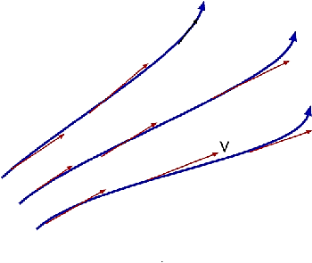
Path Line:
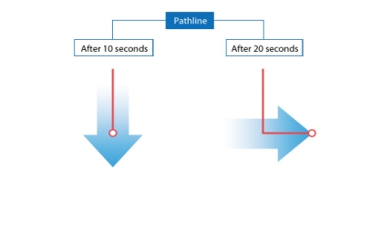
- Path lines are the trajectories that are followed by the particles of each body. This can be thought of as "recording" the method of a liquid object in a certain flow of time. The direction of the path to be determined will be determined by the fluid flow of the liquid at each time point.
- Path Lines - A line path is a line followed by water particles as they travel over a period of time. Thus the line of motion indicates the direction of the velocity of the same particle of liquid at successive times. While the formulation shows the speed direction of many liquid particles at the same time.
- The liquid particle always moves the tangent to the grid, so, with a constant flow, the lines of direction and direction are the same.
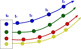
Streak Line and Stream Tube:
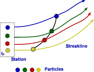
Redirect is a line that positively connects velocity vectors over a period of time. In other words, the flow diagram presented in simple lines is similar to the abstract flow at the same time.
A streak line is a curved line formed by a string of liquid particles that pass through a certain area. An example of a streak line is the smoke path from the chimney.
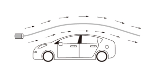
Path line is the process followed by liquid particles. One example of a path line is a method described as a balloon floating in the air.
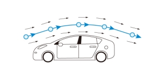
With constant flow, streamline, streak line, and path line are the same line. The constant flow of time is called the steady flow. On the other hand, the flow that varies with time is called transient flow. In the short-term flow, streamline, streak line, and path line are all different lines.
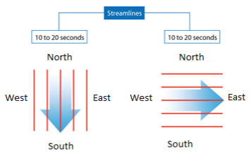
The streak line represents all the points that have passed in one place. In this case, where the streak line can be compared to represent the chimney from the chimney, the streak line goes south within the first ten seconds because all the smoke goes south. Then, when the wind blows eastward, all the smoke particles that start to move south (released by Time <10 seconds) begin to be placed eastward. New smoke particles (released Time> 10 seconds) are oriented eastward. After 20 seconds the streak line is in the right corner as shown on the right
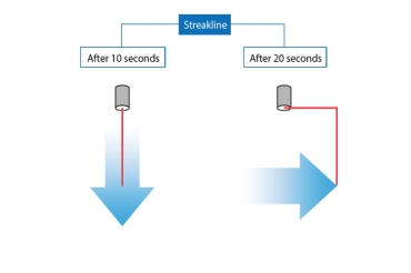
The path line goes south within the first 10 seconds as a streak line. The path line can be thought of as a process followed by a balloon floating in the air. When the wind shifts eastward, the balloon begins to move eastward. The path line goes east from where the direction of the wind is changed. As a result, after 20 seconds the path line bends at the right angle as shown on the right
Key Takeaway:


For a rigid body of mass m, Newton’s second law is expressed as


The product of the mass and the velocity of a body is called the linear
Momentum or just the momentum of the body.
The momentum of a rigid body of mass m moving with a velocity  is,
is,

Then Newton's second law can be written as follows: the rate of change of a body's momentum equals the net force acting on the body. This statement is more in line with Newton's original statement of the second law, and it is better suited for application in fluid mechanics when analysing forces created by fluid stream velocity changes. As a result, Newton's second law is often known as the linear momentum equation in fluid mechanics.
When the net force acting on a system is zero, the system's momentum remains constant, and hence the momentum of such systems is conserved. The conservation of momentum principle is what this is called.
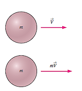
Force, acceleration, velocity, and momentum are all vector quantities, meaning they have both a magnitude and a direction. Furthermore, because momentum is a constant multiple of velocity, the direction of momentum is the same as the direction of velocity. Using magnitudes, any vector equation may be stated in scalar form for a certain direction.

The counterpart of Newton’s second law for rotating rigid bodies is
Expressed as,


It can also be expressed in terms of the rate of
Change of angular momentum  as,
as,


For a rigid body rotating about a fixed x-axis, the angular momentum equation can be written in scalar form as

The rate of change in angular momentum of a body is equal to the net torque acting on it, according to the angular momentum equation.
When the net torque acting on a rotating body is zero, its total angular momentum remains constant, and hence the angular momentum of such systems is conserved. This is known as the conservation of angular momentum principle and is expressed as

Control Volume Selection:
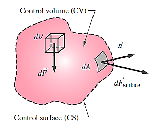
Any arbitrary region in space through which fluid flows can be chosen as a control volume, and its boundary control surface can be fixed, movable, or even deforming during flow. The application of a basic conservation law is basically a systematic technique for bookkeeping or accounting of the quantity in question, thus it's critical that the control volume's limits are well defined during an analysis. Furthermore, because the flow rate of any quantity into or out of a control volume is determined by the flow velocity relative to the control surface, it is critical to know whether the control volume is at rest or moves during flow.
Many flow systems include stationary hardware that is securely attached to a solid surface, and these systems are best evaluated with fixed control volumes.
It is frequently more convenient to allow the control volume to move or deform when examining flow systems that are moving or deforming.
The control volume in this case moves with velocity,

Forces acting on a control volume:
Body forces that act across the control volume's entire body (such as gravity, electric, and magnetic forces) and surface forces that act on the control surface (such as pressure and viscous forces, as well as reaction forces at points of contact) are the forces that act on a control volume.
In control volume analysis, the sum of all forces acting on the control volume at a particular instant in time is represented by,

Each volumetric portion of the control volume is subjected to body forces. Within the control volume, the body force acting on a differential element of fluid of volume dV.
Each section of the control surface is subjected to surface forces.
Gravitational force acting on a fluid element:

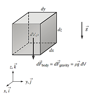
In Cartesian coordinates we adopt the convention that gravity acts in the negative z-direction

Total body force acting on control volume:

Because surface forces have both normal and tangential components, they are more difficult to analyse. Furthermore, whereas the physical force acting on a surface is unaffected by the orientation of the coordinate axes, the force's description in terms of its coordinate components does.
Furthermore, having each of the control surfaces aligned with one of the coordinate axes is an unusual occurrence. We are compelled to define a second-order tensor called the stress tensor, while not wanting to get too deep into tensor algebra.
Stress tensor in Cartesian coordinates:


They are composed of pressure and viscous stresses.
The off-diagonal components are called shear stresses, since pressure can act only normal to a surface, shear stresses are composed entirely of viscous stresses.
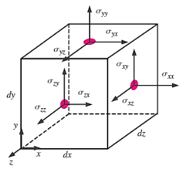
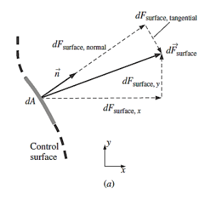
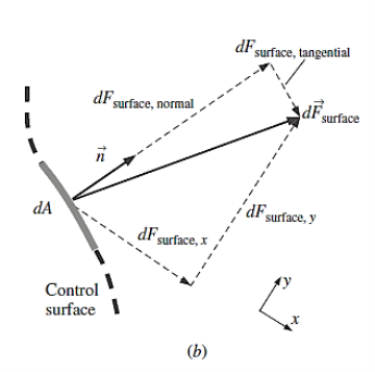
A second-order tensor and a vector are dot-product to produce a second vector; this operation is also known as the contracted product or the inner product of a tensor and a vector.
Surface force acting on a differential surface element:

Total surface force acting on control surface:


Total force:

Linear Momentum Equation:


Noting that both the density and velocity may change from point to point within the system, Newton’s second law can be expressed more generally as,

Were,


As a result, Newton's second law states that the sum of all external forces acting on a system equals the temporal rate of change of the system's linear momentum. This statement is true for an inertial coordinate system or inertial reference frame, which is a coordinate system that is at rest or moves at a constant velocity.
The Reynolds transport theorem can be expressed for linear momentum as


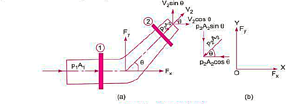


Key Takeaway:


Unfortunately, velocity is not uniform across most inlets and outlets of practical engineering significance. Nonetheless, it turns out that the control surface integral of Equation may be converted to algebraic form. But a dimensionless correction factor  , called the momentum-flux correction factor, is required
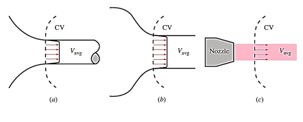
The algebraic form of Equation for a fixed control volume is

Where a unique value of momentum-flux correction factor is applied to each inlet and outlet in the control surface.

For the general case, we define  such that the integral form of the momentum flux into or out of the control surface at an inlet or outlet of cross-sectional area
  can be expressed in terms of mass flow rate
  through the inlet or outlet and average velocity
  through the inlet or outlet.

For the case in which density is uniform over the inlet or outlet and  is in the same direction as
  over the inlet or outlet, we solve


According to Newtons second Law,


Forces present in fluid flow,


Reynold’s equation of motion

Navier strokes equation of motion

Euler’s equation of motion

Euler’s Equation for Motion along streamline
Consider a cylindrical element,


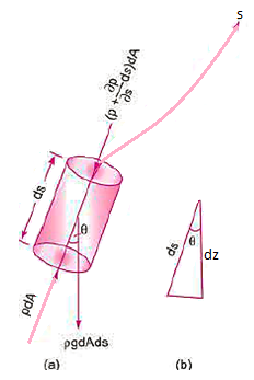


The resultant force on the fluid element in the direction of s must be equal to the mass of fluid element x acceleration in the direction s.


Now,


So,


Dividing by 


As,


Key Takeaway:


Bernoulli's equation is obtained by integrating the Euler's equation of motion,


Assumptions:
- The fluid is ideal, i.e., viscosity is zero
- The flow is steady
- The flow is incompressible
- The flow is irrotational.
Bernoulli's equation for Real liquid:
The Bernoulli's equation assumes that the fluid is non-viscous and thus frictionless. However, all genuine fluids are viscous and so provide flow resistance. As a result, there are always some losses in fluid flows, and these losses must be taken into account when applying Bernoulli's equation. Thus, for actual fluids between locations I and 2, Bernoulli's equation is


Key Takeaway:

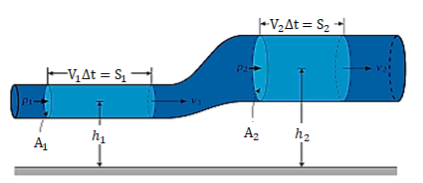
- In fluid dynamics, Bernoulli's policy states that fluctuations in fluid flow occur simultaneously with a decrease in stationary pressure or a decrease in the available fluid strength.
- The program is named after Daniel Bernoulli who published it in his book Hydrodynamics in 1738. Although Bernoulli found that pressure decreased as the flow rate increased, it was Leonhard Euler who discovered Bernoulli's measurement in a normal way in 1752.
- The principle applies only to isentropic flow: where the effects of irreversible processes (such as disorder) and non-adiabatic processes (e.g. Heat radiation) are small and ignored
- Bernoulli's system can be applied to a variety of fluid flows, leading to a variety of Bernoulli's calculations; there are different types of Bernoulli's figure for different types of flow.
- The simplest form of Bernoulli's equation is valid for unmistakable flow (e.g. High flow of air and gases running through a low March number). Advanced forms can be used for pressurized flow in high March numbers (see Bernoulli statistical availability).
- Bernoulli's policy can be based on the principle of energy conservation. This means that, with a constant flow, the sum of all the energies in the liquid along the simplest path is the same at all points in that flow path. This requires that the amount of kinetic energy, potential energy and internal energy remain constant.
- Thus an increase in the velocity of a liquid - i.e. an increase in its kinetic energy (strong pressure) - occurs simultaneously a decrease (total energy) of its energy (including constant pressure) and internal energy. When the liquid comes out of a pond, the amount of all kinds of energy is the same in all streamlines because in the pond the energy of each unit (total pressure and gravity ρ g h) is the same everywhere.
- Bernoulli's goal can also be found directly in Isaac Newton's Second Movement of Movement. If a small amount of fluid flows horizontally from a high-pressure area to a low pressure region, then there is more pressure behind than before. This gives the net power by volume, speeding it up with ease.
- Fluid particles are subject to pressure and weight only If the fluid flows horizontally and partially along a certain flow path, where the speed increases it may be due to the fluid in that phase moving from the high-pressure region to the low-pressure region; and if its speed decreases, it may be because it has moved from a low-pressure region to a high-pressure region.
- As a result, inside the liquid flowing upwards, the greatest velocity occurs when the pressure is too low, and the lowest velocity occurs when the pressure is too high.
The ratio of kinetic energy of the flow per second based on real velocity across a segment to kinetic energy of the flow per second based on average velocity across the same section is known as the kinetic energy correction factor.
The symbol for the kinetic energy correction factor will be presented  , and it will be stated mathematically as described here.

Key Takeaway:


Pitot probes (also known as Pitot tubes) and Pitot-static probes are frequently used for flow rate measurement and are named after the French engineer Henri de Pitot (1695–1771). A Pitot probe is just a tube with a pressure tap at the stagnation point that measures stagnation pressure, whereas a Pitot-static probe has a stagnation pressure tap as well as many circumferential static pressures taps that measure both stagnation and static pressures.
The Pitot-static probe uses the Bernoulli equation to calculate local velocity by detecting the pressure differential. It is made out of a thin double-tube that is aligned with the flow and is coupled to a differential pressure metre. At the nose, the inner tube is totally exposed to flow, therefore it monitors the stagnation pressure there (point 1). The outer tube is sealed at the nose but has openings on the side of the outer wall (point 2), which allows it to measure static pressure.
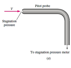
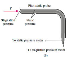
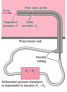
The Bernoulli equation is suitable for incompressible flow with sufficiently high velocities (such that frictional effects between points 1 and 2 are minimal) and can be stated as,

Noting that,

Since the static pressure holes of the Pitot-static probe are arranged circumferentially around the tube &  because of the stagnation
Conditions
The flow velocity 

The volume flow rate can be calculated if the velocity is measured at a site where the local velocity equals the average flow velocity.

Because it has no moving parts, the Pitot-static probe is a simple, low-cost, and very reliable gadget. It also creates a very tiny pressure decrease and normally has little effect on the flow. However, it is critical that it is properly aligned with the flow in order to avoid major errors caused by misalignment.
In addition, the difference between the static and stagnation pressures (the dynamic pressure) is proportional to the fluid density and the square of the flow velocity. It can be used to determine the velocity of liquids as well as gases. Given the low density of gases, the flow velocity must be sufficiently high for a measurable dynamic pressure to emerge when the Pitot-static probe is employed for gas flow.
Key Takeaway:

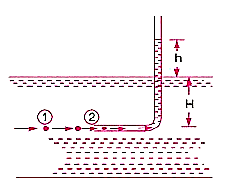


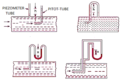
Key Takeaway:

A venturi meter is a device used for measuring the rate of a flow of a fluid flowing through a pipe it consists of three parts:
i) A short converging part, ii) Throat, and (iii)Diverging Part
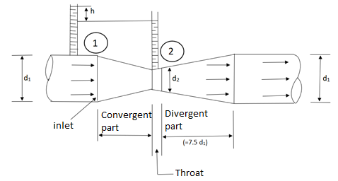
It is based on the principle of Bernoulli’s equation.
Expression for Rate of flow through venturi meter
Consider a venturi meter fitted in a horizontal pipe through which a fluid is following as shown in fig.
Let d1 = diameter at inlet or at section (1)
P1= pressure at section (1)
V1 = velocity of fluid at section (1)
a1= area of section (1) =
And d2, P2, V2, a2 are corresponding values at section (2)
Applying Bernoulli’s equation at section (1) and (2) we get

As pipe is horizontal hence z1 = z2


But  is the difference of pressure heads at section land 2 and it is equal to h

Substituting this value of  in the above eqn we get.

Now applying continuity equation at section 1 and 2
a1 v1 = a2 v2

Substituting this value of v1 in equation


Q = a2v2


Above equation gives the discharge under ideal conditions and is called, theoretical discharge Actual discharge will be less than theoretical discharge.

Where Cd = co-efficient of venturi meter and its value is less than 1.
Key Takeaway:


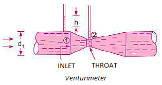
The differential generating flowmeter, often known as a Venturi, has a long history of application in a variety of fields. The Venturi is one of the most widely used flowmeters due to its simplicity and dependability. The Venturi can monitor fluid flowrates with minimal total pressure loss because it has no moving parts or sudden flow limitations.
The Bernoulli effect is at the heart of the Venturi flowmeter's operation. The Venturi determines the flow rate of a fluid by lowering the cross-sectional flow area in the flow channel and creating a pressure difference. Following the generation of the pressure difference, the fluid is routed via a pressure recovery exit section, which recovers up to 80% of the differential pressure generated at the throat.
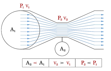
The fluid, whether liquid or gaseous, enters the Venturi at the position with the cross-sectional area A1, pressure P1, and velocity V1 in the illustration above. These qualities combine to form the fluid's potential and kinetic energy at a single point. In a closed system, energy is conserved, which means that the sum of potential and kinetic energy at one point must match the sum of potential and kinetic energy at all other points in the system.
If potential energy falls at one location, kinetic energy must rise proportionately at the same site. The fluid now reaches the Venturi's throat through a region A2 that is smaller than A1. Because mass cannot be generated or destroyed in a closed system (the law of conservation of mass states that what goes in must come out), the volumetric flowrate at area A1 must match the volumetric flowrate at area A2.
If A2 has a smaller area than A1, the fluid must travel faster to maintain the same volumetric flowrate. According to Bernoulli's equation, an increase in velocity causes a drop in pressure. As a result, knowing the pressure and cross-sectional area at two points allows one to compute the fluid's velocity. The flowrate can be calculated using the fluid's velocity and density.
It is a device that measures the rate at which a fluid flows through a conduit. In comparison to the venturi meter, this is a less expensive equipment. It operates on the same premise as a venturi meter. It is made out of a flat circular plate with a circular sharp-edged aperture that is concentric with the pipe. The orifice diameter is usually 0.5 times the pipe diameter, however it can range between 0.4 and 0.8 times the pipe diameter.
A differential manometer is connected at section (1), which is about l.5 to 2.0 times the pipe diameter upstream from the orifice plate, and section (2), which is roughly half the orifice diameter on the downstream side of the orifice plate.
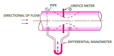


Applying Bernoulli’s Equation,


But,


Now, Section 2 is Vena Contracta


By continuity equation,


So,


The discharge,


Simplifying above expression,
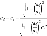
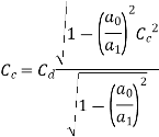
As,

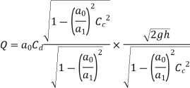


Key Takeaway:

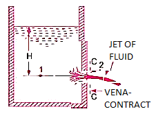
Consider the following tank, which has a circular hole in one of its sides. Let H represent the liquid's head above the orifice's centre. The liquid flowing through the aperture generates a jet of liquid with a cross-sectional area smaller than the orifice. The area of the fluid jet continues to shrink until it reaches its smallest point at section C-C. This segment is half the diameter of the orifice's diameter away.
The streamlines are straight and parallel to each other in this portion, and perpendicular to the orifice plane. Vena-contracta is the name of this section. Beyond this point, the jet diverges and is drawn downward by gravity.

z1 = z2


Hydraulic Coefficients:


Key Takeaway:


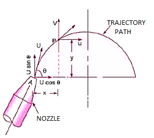
A free liquid jet is a water jet that emerges from a nozzle into the atmosphere. The path that the free jet takes is parabolic.


Maximum Height attained by the jet:


Time of Flight:


Time to reach highest point:

Horizontal Range of the jet:

Value of  for maximum range:


Key Takeaway:


The aperture is referred to as a large orifice if the liquid head is less than 5 times the depth of the orifice. The velocity across the whole cross-section of the jet is assumed to be constant in the case of a tiny aperture, and discharge can be estimated.

But in case of a large orifice, the velocity is not constant over the entire cross-section of the jet hence Q cannot be calculated from above equation.
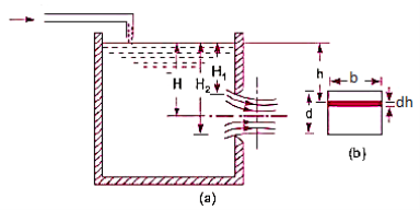


Key Takeaway:

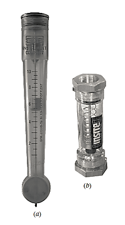
The variable-area flowmeter, also known as a rotameter or float metre, is a simple, dependable, inexpensive, and easy-to-install flowmeter with little pressure drop and no electrical connections that provides a direct reading of flow rate for a wide range of liquids and gases. A variable-area flowmeter is constructed up of a vertically tapered conical transparent tube made of glass or plastic with a free-moving float within.
The float rises within the tapered tube as fluid flows through it until a point where the float weight, drag force, and buoyancy force balance each other, and the net force acting on the float is zero. Simply match the position of the float against the graduated flow scale outside the tapered transparent tube to ascertain the flow rate.
High winds have been known to bring down trees, smash power lines, and blow hats and umbrellas away. This is due to the fact that the drag force increases as the flow velocity increases. The float's weight and buoyancy force are constant, but the drag force varies with flow velocity. In addition, owing of the increased cross-sectional area, the velocity along the tapered tube reduces in the flow direction.
The float settles at a specific velocity that provides enough drag to balance the float's weight and buoyancy force, and the location where this velocity occurs around the float is where the float settles. The tube's degree of tapering can be adjusted so that the vertical rise changes linearly with flow rate, allowing the tube to be linearly calibrated for flow rates. The fluid can also be seen flowing through the clear tube.
Variable-area flowmeters come in a variety of shapes and sizes. The previously mentioned gravity-based flowmeter must be installed vertically, with fluid entering from the bottom and exiting from the top. The drag force is balanced by the spring force in spring-opposed flowmeters, which can be mounted horizontally. Instead of a float, a loose-fitting piston is used in another form of flowmeter.
Variable-area flowmeters have a typical accuracy of +/- 5%. As a result, these flowmeters are not suitable for applications requiring precise measurements. Some manufacturers, on the other hand, claim accuracies of the order of 1%. Furthermore, because these metres rely on visual inspection of the float's location, they cannot be used to measure the flow rate of fluids that are opaque or unclean, or fluids that cover the float, as these fluids prevent visual inspection. Finally, glass tubes are prone to breaking, posing a safety risk when handling dangerous fluids. Variable-area flowmeters should be deployed in low-traffic sites in such applications.
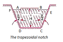
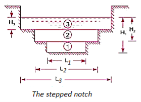
A notch is a device that is used to measure the rate at which a liquid flow through a narrow channel or a tank. It's a small aperture in the side of a tank or a small channel where the liquid surface in the tank or channel lies below the top edge of the opening.
A web is a concrete or masonry structure that is built in an open channel where the flow takes place. It usually takes the shape of a vertical wall with a sharp edge at the top that runs the length of the open channel. The notch is minor in comparison to the weir, which is larger. The notch is usually made of metal plate, whereas the weir is usually made of concrete or masonry.
1) Nappe or Vein refers to the sheet of water that flows through a notch or over a weir.
2. Crest or Sill is the bottom edge of a notch or the top of a weir over which water flows.
Classification of notches and weirs
Notches are classified as:
- According to the shape of the opening
Rectangular notch
Triangular notch
Trapezoid notch
Stepped notch
- According to the effect of the sides on the nappe:
Notch with end contraction
Notch without end contraction or suppressed notch
Weirs are classified as:
- According to the shape of the opening
Rectangular weir
Triangular weir
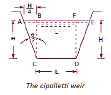
Trapezoid weir ( Cipolletti weir)
- According to the Shape of crest:
Sharp-crested weir
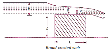
Broad-crested weir
Narrow-crested weir
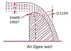
Ogee-shaped weir
- According to the effect of sides on the emerging nappe:
Weir with end contraction
Weir without end contraction

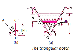
Because of the following reasons, a triangular notch or weir is favoured over a rectangular notch or weir:
- The discharge statement for a right-angled V-notch or weir is relatively straightforward.
- A triangular notch delivers more accurate findings than a rectangular notch when measuring low discharge.
- In the event of a triangle notch, only one reading, H, is necessary for discharge computation.
- A triangular notch does not require ventilation.
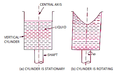
The flow of a fluid along a curved path or the flow of a spinning mass of fluid is referred to as a 'Vortex Flow.' There are two forms of vortex flow:
- Forced vortex flow
Forced vortex flow is defined as a type of vortex flow in which the fluid mass must be rotated by an external torque. In this form of flow, the fluid mass spins at a constant angular velocity.
The tangential velocity of any fluid particle is

- Free vortex flow
The term "free vortex flow" refers to a flow in which no external torque is required to rotate the fluid mass. Thus, in the case of a free vortex, the liquid rotates due to the rotation which that has been imparted to the fluid previously.
In a free vortex, the relationship between velocity and radius is obtained by setting the magnitude of external torque to zero, or by setting the time rate of change of angular momentum to zero, i.e., the moment of momentum must be zero.


Integrating,

Equation of Motion for Vortex Flow:
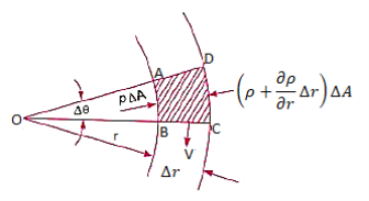


Pressure Gradient in vertical plane is given by hydrostatic law,

So,


Equation of Forced Vortex Flow:


If the points 1 & 2 lie on the free surface, then 


If point 1 lies on the axis of rotation,


Equation of Free Vortex Flow:
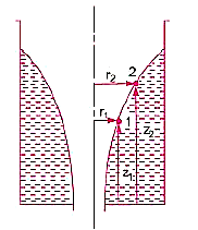

As, 
So,


Key Takeaway:


Examples
Q.1. An oil of sp.gr 0.8 is flowing through a venturi meter having inlet diameter 20 cm & throat diameter 10cm. The oil mercury differential nanometres show a reading 25 cm. Calculate the discharge of oil through the horizontal venturi meter Take cd = 0.98.
Solution:
S1= 0.8
Sm =13.6
d1=0.2m
d2=0.1m
x=0.25m
Cd=0.98
A1 = π/4*d12 = π/4*0.22 = 0.0314 m2
A2 = π/4*d22= π/4* 0.12 = 7.85*10-3m2
 = 4m
= 4m
Q = 
= 
=0.0705 m3/sec
Q.2. The inlet & throat diameters of horizontal venturi meter are 30cm & 10cm respectively. The liquid flowing throat the meter is water, the pressure intensity at inlet is 13.734 N/cm2 while the vacuum pressure head at the throat is 37cm of mercury. Find rate of flow Assume that 4%of the differential head is lost between the inlet & throat. Find also the value Cd for the venturi meter.
Solution:
d1 =0.3m
d2= 0.1m
p1=13.734 x10⁴N/m2
Vacuum pressure head = - 0.37m of Hg
hf = 4 % of h = 0.04h
A1= x d12 =
 =0.0706m2
A2=  x d22=
 =
=
P2 = w *Vacuum pressure head
= (13.6 x 9810) x -0.37
= - 49.37 x10³ N/m2
h=  =
=
= 19.03 m
hf= 0.04h = 0.04 x 19.032 = 0.7613m
Cd =  =
= = 0.98
Q=
= 
= 0.149 m3/sec
Q.3. A 30cm x 15cm venturi meter is provided a vertical pipeline carrying oil of specific gravity 0.9, The flow being upwards. The different in elevation of the venturi meter is 30cm. The differential U tube mercury manometer shows a gauge deflection of 25cm calculate i) the discharge ii) pressure difference between the entrance section throat section. Take Cd = 0.98.
Solution:
d1 = 0.3m
d2 = 0.15m
SL =0.9
Z1=0
Z2 = 0.3 M
X = 0.25 M
A1 = π/4 * d12 = π/4*0.32 = 0.0706m2
A2 = π/4 * d22 = π/4*0.152 = 0.0176m2
h= - 1) = 0.25 (
Q =
= 
=0.149 m3/sec
h=  +(z1-z2)
3.53 =  +(0 - 0.3)
P1-P2 =33.81 x 10³ N/m2
Q.4. Find the discharge of water flowing through a pipe 30cm diameter placed in on inclined position where a venturi meter is inserted, having a throat diameter of 15 cm. The difference of pressure between the main & throat is measured by a sp.gr 0.6 in an inverted tube which gives a reading of 30 cm. The loss of head between the main & threat 0.2 times the kinetic head of the pipe.
Solution:
d1 = 0.3 m
d2 = 0.15m
Sm = 0.6
x= 0.3m
hL=0.2 
A1 =  * d12 =
  * 0.32 = 0.0706m2
A2 =  *d22 =
  * 0.152 = 0.0176 m2
h = x [1-  ] = 0.3 [1-
  ] = 0.12m
Applying Bernoulli’s eqn. At section 1& 2
:.  +
+  + Z1 =
 +
+ + Z2+ hL
( -
-  ) + (Z1-Z2) =
 -
-  + hL
+ hL
Applying Continuity eqn. At section (1) & (2)
A1V1 =A1 V2
 = V2
= V2
 = V2
= V2
:. V2 = 4V1
:. ( -
-  ) + (Z1-Z2) =
 -
-  +
+ 
:. h = 
:. 0.12 = 
:.V1 = 0.393m/s
:.Q = A1 V1
= 0.0706 x 0.393
= 0.0277 m3/sec
Q.5. The velocity of a flow is given by v = -x i + 2y j + (5 - 2) k. Derive the equation of streamline passing through a point (2, 1, 1).
Solution:
u = -x, v = 2y and w = 5-z
The streamline, put the value of u, v and w

Consider,


Stream line passing through x=2, y=1, z= 1


Now consider,


Stream line passing through x=2, z=1


Q.6. For the three-dimensional flow, the velocity distribution is given by u-x, v-4-2y, w z-2. What is the streamline equation passing through (1.-2, 3).
Solution:
The streamline,

Put the value of u, v and w

Consider 
By integrating


Streamline passing through x=1 y= =-2


Now considering


From equation

Q.7. The velocity component in a steady flow are u=2kx, v= 2ky, w = - 4kz. What is the through the point (1, 0, 1).
Solution:
The streamline,

Put the value of u, v and w

Now considering


Streamline passing through x = 1, z=3,


This is the equation of streamline passing through the point (1,0,1)
Q.8. The velocity field for a two-dimensional flow is given by V= 4x³i-12x²yj. What is the equation of streamlines?
Solution:
Velocity vector v = 4x'i-12x²yj
Velocity component u = 4x², v = -12x²y
Streamline


By integrating,
3 log x = -log y + log C


The curve defined by x³y = C₁, C₂, C, ...etc.
Q.9. A stream function is given by  check if the flow is rotational and satisfies continuity equation
Solution:

By definition


Velocity


1) Irritational flow

2) Continuity equation


The flow is not continuous
Q.10. Determine whether the following specified flows are rotational or otherwise. Determine the expression for the velocity potential in case of irrotational flow
Solution:

For rotational flow


Flow is rotational.
Q.11. The velocity potential function is given by an expression 
1) Find the velocity components in x and y direction
2) Show that  represents a possible case of flow
Solution:

Case I) the partial derivation of  w.r.t x and y are


The velocity components u and v


Case II) The value of  represents a possible case of flow if it satisfy the laplace equation


 Represents possible case of flow
Q.12. The velocity potential function for a two-dimensional flow is  at a point P (4, 5) determine the velocity and Velocity potential.
Solution:

Differential w.r.t x
Hence

By definition of 


Velocity at P (4, 5)


Flow is continuous
Q.13. Water is flowing through a tapered pipe having diameters 300 mm and 150 mm at section 1 and 2 respectively. The discharge through the pipe is 40 litre/sec. Section 1 is 10 m above datum and section 2 is 6 m above datum. Find the intensity of pressure at section 2 if that at section 1 is.
Solution:
Given
Q = 40 litre/sec=0.04 m²/sec
Z₁ = 10m
Z₂ =6m
d₁ =300mm=0.3 m
d2 = 150 mm-0.15m
P1 = 400 kN/m²
To find: P:
Area


By continuity equation,


By Bernoulli's equation


The intensity of pressure of section 2 is 436.84 kN/m²
Q.14. A pipe has a length of 200 m with a slope of 1 in 100. The diameter of pipes changes from 1.0 m at higher end to 0.5 m at lower end. Find the pressure at the lower end if the discharge flowing through pipe is 5.00 m/min and pressure at higher end is 45 kN/m².
Solution:
L = 200 m,
P₁ =45 kN/m²
Slope = 1 in 100. z₁ = 0,
d₂ -0.5 m
Q = 5 m/min =5/60 = 0.0833 m/sec
To find: P₂
Slope of pipe is 1 in 100


(Since it is below z₁
i.e., datum, it is considered negative) = -2m
By continuity equation


By Bernoulli's equation


Multiplying by 9.81

Q.15. In a vertical pipe conveying oil of specific gravity 0.8, two pressure gauges has been installed at A and B, where diameters are 16 cm and 8 cm respectively. A is 2 m above B. The pressure gauge readings have shown that pressure at B is greater than at A by 0.981 N/cm². Neglecting all losses calculate flow rate,
Solution:
Specific gravity S=0.8
Diameter at A, dA = 16 cm = 0.16 m
Diameter at B, dB = 8 cm=0.08 m ZA = 2 m, ZB=0
PB=PA+0/981 N/cm^2

Pressure difference PB-PA= 9.81KN/m^2
Area


By continuity equation,


By Bernoulli's equation


Discharge

Q.16. The top and bottom diameters of a 2m long vertical tapering pipe are 100 mm and 50 mm respectively. Water flows down the pipe at 30 liters por second. Find the pressure difference between the two ends of the pipe.
Solution:
Q = 30 Lps = 0.03 m³/sec,
d1 = 0.05 m. d₂ = 0.1 m, z₁ = 0, z₂ = 2 m
Area


By continuity equation,


By Bernoulli's equation


:. The pressure difference between two ends of pipe is 10.415x 10³ Pa
Q.17. Obtain an expression for pressure drop from inlet to throat in a horizontally mounted venturi meter in terms of rate of volume flow (0) and inlet diameter (D) for inlet throat diameter ratio is equal to 2.
Solution:
d1= Inlet diameter = D
Inlet diameter /Throat diameter= 2
d2 = Throat diameter = D/2
By continuity equation


By Bernoulli's equation


Q.18. A venturi meter has an area ratio 9.1, the large diameter being 30 cm. During the flow, the recorded pressure head in the large section is 7.75 m and that at the throat is 5.5 m. Find the discharge through the meter if C,0.98.
Solution:


Discharge of inlet
d1 = 0.3 m
Pressure at inlet 
Pressure head at throat 
Coefficient of discharge Cd, = 0.98
Area


Pressure head

Discharge


References:
- Fluid Mechanics and Hydraulic Machines by R.K. Bansal, Laxmi Publications
- Fluid Mechanics: Fundamentals and Applications by Y. A. Çengel and J. M. Cimbala, by McGraw-Hill
- Fluid Mechanics by Frank .M. White, mcgraw Hill Publishing Company Ltd.
- Fundamentals of Fluid Mechanics by munson, Wiley India Pvt. Ltd