Unit - 7
Flow through pipes
When a fluid flows through a pipe, it encounters resistance, which causes part of the fluid's energy to be lost.
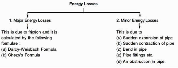
Loss of energy (or head) due to friction:
- Darcy-Weisbach Formula
The Darcy-Weisbach equation is used to calculate the loss of head (or energy) in pipes owing to friction.


Were,


Chezy's Formula:


So,


Where,


Key Takeaway:


Major loss of energy refers to the loss of head or energy caused by friction in a pipe, whereas minor loss of energy refers to the loss of energy caused by a change in magnitude or direction in the velocity of the following fluid.
- Loss of head due to sudden enlargement
- Loss of head due to sudden contraction
- Loss of head at the entrance of a pipe
- Loss of head at the exit of a pipe
- Loss of head due to an obstruction in a pipe
- Loss of head due to bend in the pipe
- Loss of head in various pipe fittings
Because the above losses are minor in comparison to the loss of head due to friction in a lengthy pipe, they are referred to as minor losses and can even be overlooked without causing major inaccuracy. In the event of a short pipe, however, these losses are comparable to head loss due to friction.
Loss of Head Due to Sudden Enlargement:
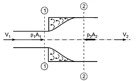
Consider a liquid flowing through a conduit that suddenly expands, as depicted. Before and after the enlargement, consider two parts (1)-(1) and (2)-(2).
Applying Bernoulli’s Equation:


Consider the control volume of liquid between sections 1-1 and 2-2. Then the force acting on the liquid in the control volume in the direction of flow is given by


Change of momentum,

Using continuity equation


Change of momentum,

Now net force acting on the control volume in the direction of flow must be equal to the rate of change of momentum or change of momentum per second.


So,


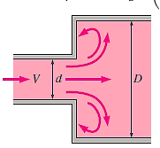
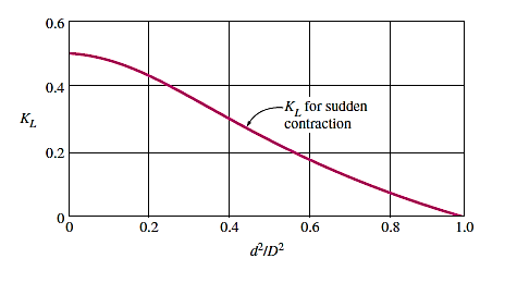
Loss of Head Due to Sudden Contraction:
Consider a liquid running through a pipe with an abrupt area contraction, as depicted. Before and after contraction, consider parts 1-1 and 2-2. As liquid flows from a large pipe to a smaller pipe, the flow area decreases until it reaches a minimum at section C-C, as depicted. Vena-contracta is the name given to this section C-C. A dramatic increase of the region occurs after section C-C. The sudden loss of head is actually owing to a sudden expansion of the Vena-contracta into a smaller channel.
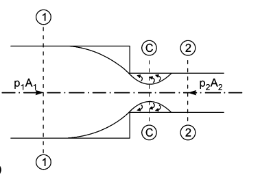
Actual loss of head due to enlargement from section C-C to section 2-2 and is given by equation,

Using continuity equation


So,


Were,


If,

Then,

If the value of  is not given, then the head loss due to contraction is taken as,

Loss of Head at the Entrance of a Pipe:
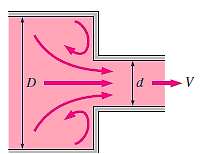
When a liquid enters a conduit that is connected to a huge tank or reservoir, there is a loss of energy. This is analogous to the loss of a head as a result of a rapid constriction. The amount of loss is determined by the type of entrance. This loss is significantly more for a sharp edge entrance than for a rounded or bell mouthed opening. The value of head loss at the entrance (or inlet) of a pipe with sharp cornered entrance is taken in practise as,

Loss of Head at the Exit of Pipe:
This is the loss of head (or energy) caused by the velocity of liquid at the pipe's outlet, which is dissipated either as a free jet (if the pipe's outlet is free) or in the tank or reservoir (if the pipe's outlet is connected to the tank or reservoir).

Loss of Head Due to an Obstruction in a Pipe:
When there is an impediment in a pipe, energy is lost due to a reduction in the area of the pipe's cross-section at the blockage. There is a dramatic increase of the flow region beyond the obstacle, resulting in loss of head.
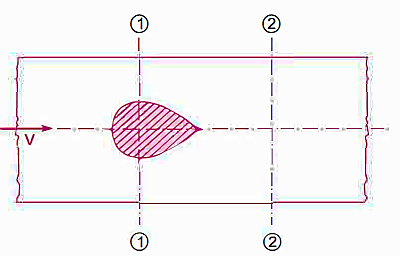


A vena-contracta is produced beyond section 1-1 as the liquid flows, after which the stream of liquid widens again and the velocity of flow at section 2-2 becomes uniform and equal to the pipe's velocity, Vin. The flow of liquid through sudden expansion is analogous to this condition.

Then loss of head due to obstruction = loss of head due to enlargement from vena-contracta to section 2-2,

From continuity,

Then,


So,


Hence,

Loss of Head due to Bend in Pipe:
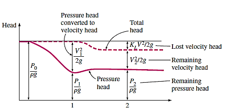
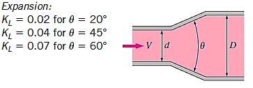
When there is a bend c in a pipe, the velocity of the flow varies, causing the flow to separate from the boundary and the development of eddies. As a result, the energy is lost. The head loss in a pipe due to bending is given as,

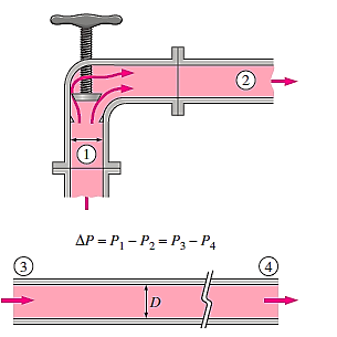
The value of K depends on,
- Angle of bend
- Radius of curvature of bend
- Diameter of pipe
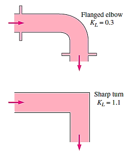
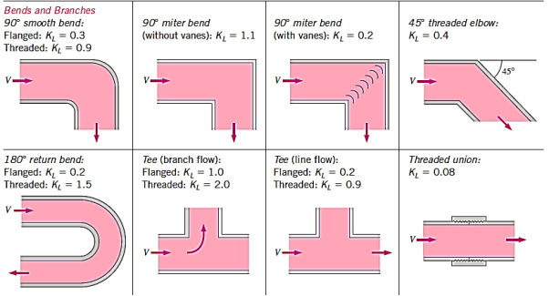
Loss of head in various pipe fittings:
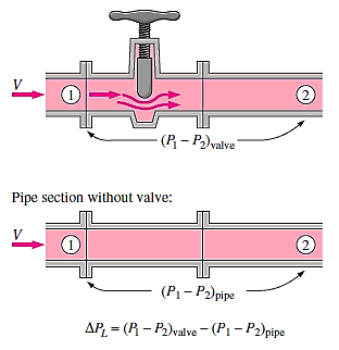
- Valves
- Couplings
- Etc

Key Takeaway:


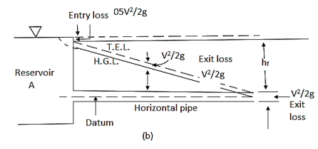
Hydraulic Grade Line:
It is described as the line that gives the total of the pressure head  and datum head
  of a flowing fluid in a pipe with respect to some reference line, or the line obtained by combining the tops of all vertical ordinates, displaying the pressure head of a flowing fluid in a pipe from the pipe's centre. It is abbreviated as H.G.L. (Hydraulic Gradient Line).
Total Energy Line:
It is the line that represents the sum of the pressure head, datum head, and kinetic head of a flowing fluid in a pipe in relation to some reference line. It's also known as the line formed by connecting the tops of all vertical ordinates displaying the sum of pressure and kinetic head from the pipe's centre. It is abbreviated as T.E.L. (Total Energy Line).
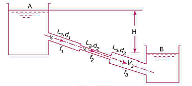
L1, L2,L3 = Length of pipes 1, 2 and 3 respectively
d1, d2, d3 = diameters of pipes 1, 2, 3 respectively
v1, v2, v3 = velocity of flow through pipes 1, 2, 3
f1, f2, f3 = coefficients of frictions for pipes 1, 2, 3
H = difference of water level in the two tanks
The discharge passing through each pipe is same

The difference in liquid surface levels is equal to the sum of the total head loss in the pipes.

If minor losses are neglected, then above equation becomes as

Flow in Parallel Pipes:


In this arrangement, the loss of head for each branch pipe is same.
Hence, Loss of head for branch pipe 1 = Loss of head of branch pipe 2

Key Takeaway:


This is described as a pipe of uniform diameter with a head and discharge loss equivalent to the head and discharge loss of a composite pipe made up of numerous pipes of various lengths and diameters.
The corresponding pipe's consistent diameter is referred to as the pipe's equivalent size. The length of an equivalent pipe is equal to the total of the lengths of all the pipes that make up a compound pipe.
L1= length of pipe 1 and d1 = diameter of pipe 1
L2 = length of pipe 2 and d2 = diameter of pipe 2
L3 = length of pipe 3 and d3 = diameter of pipe 3
H = total head loss
L = length of equivalent pipe
d = diameter of equivalent pipe
Total head loss in the compound pipe, neglecting minor losses


Substituting these values, we have


Head loss in the equivalent pipe,

Were,

So,

Head loss in compound pipe and in equivalent pipe is same hence equating the above equations we have


This known as Dupuit equation.
Key Takeaway:

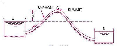
When two reservoirs are separated by a hill or high-level ground, a syphon is used to move liquid from one reservoir at a higher elevation to another reservoir at a lower elevation.
The summit is located at point C, which is the highest point on the syphon. The pressure at point C will be less than atmospheric pressure since it is above the free surface of the water in tank A. Although the pressure at C can theoretically be decreased to - 10.3 m of water, in reality it is only - 7.6 m of water, or 10.3 - 7.6 = 2.7 m of water absolute. If the pressure at C falls below 2.7 m of water absolute, dissolved air and other gases will escape from the water and condense at the summit. The water flow will be hindered.
Syphon is used in the following cases:
- To transport water between two reservoirs separated by a hill or ridge.
- To remove liquid from a tank that doesn't have an outlet.
- To clear a canal that lacks an outlet sluice.
Flowing water or other liquids are used to carry power through pipelines. The amount of power transmitted is determined by
- The weight of the liquid flowing through the pipe.
- The total head at the pipe's end.
Consider the following diagram of a pipe AB connected to a tank. The power available at the pipe's end B and the conditions for maximum power transmission will be determined as follows:
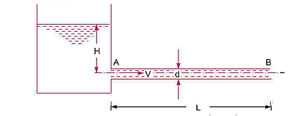


The head available at the outlet of the pipe if minor losses are neglected


Weight of water flowing through pipe per sec,


The power transmitted at the outlet of the pipe


Power transmitted at outlet of the pipe,

Efficiency of power transmission,


Condition for Maximum Transmission of Power
By differentiating the equation with respect to V and equating it to zero, the condition for maximum power transmission is established.


Maximum Efficiency of Transmission of Power:

For maximum power transmission through pipe the condition is given by equation,

So,

Key Takeaway:


The entire energy at the pipe's end is made up of pressure and kinetic energy. The whole energy is turned into kinetic energy by fitting the nozzle at the end of the pipe. When larger flow velocities are necessary, nozzles are used.
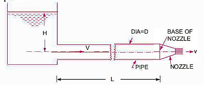


Loss of head due to friction in pipe,

Head available at the end of the pipe or at the base of nozzle


Neglecting minor losses and assuming losses in the nozzle negligible,


So,

From continuity equation in the pipe and outlet of nozzle,


So,


Discharge through nozzle,

Power Transmitted Through Nozzle:
The kinetic energy of the jet at the outlet of nozzle,

Now mass of liquid at the outlet of nozzle per second,

KE of jet at the outlet per second,

Power in kW at the outlet of nozzle

Efficiency of power transmission through nozzle,
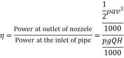


Condition for Maximum Power Transmitted Through Nozzle:


Power transmitted through nozzle,


From Continuity equation:


Power,

For maximum Power,


Diameter of Nozzle for Maximum Transmission of Power Through Nozzle:
As,

But,

So,


But H is also = total head at outlet of nozzle+ losses

So,


From Continuity equation:


So,


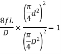

So,

Key Takeaway:


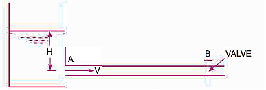
Consider the following long pipe AB, which is connected at one end to a water tank at a height of H from the pipe's centre. A valve is installed at the other end of the pipe to control the flow of water. When the valve is fully open, the water in the pipe flows at a velocity of V. If the valve is quickly closed, the momentum of the flowing water is lost, and a high-pressure wave is created as a result.
This high-pressure wave will travel through the pipe at a speed comparable to that of a sound wave, potentially causing banging noise.
This high-pressure wave also has the effect of hammering the pipe walls, which is why it's also known as water hammer.
The pressure rise due to water hammer depends upon:
- The velocity of flow of water in pipe
- The length of pipe
- Time taken to close the valve
- Elastic properties of the material of the pipe
Gradual Closure of Valve:


The valve is closed gradually in time 'T' seconds and hence the water is brought from initial velocity V to zero velocity in time seconds.


If p is the intensity of pressure wave produced due to closure of the valve, the force due to pressure wave,

So,


Head of pressure,


Were,


Sudden Closure of Valve


If the influence of friction is ignored and the pipe wall is believed to be perfectly rigid, the kinetic energy of the flowing water is changed into strain energy of water when the valve is suddenly closed.


So,


Key Takeaway:


Continuity Equation:
This is based on law of conservation of mass which states that matter cannot be created nor destroyed. In other words, the matter or mass is constant.
For one-dimensional steady flow,

Were,


As mass or mass per second is constant according to law of conservation of mass,

Differentiating,


Dividing by,


Bernoulli's Equation:
As According to Euler’s equation


- Isothermal Process


Hence,


So,


- Adiabatic Process


Hence,


So,


Momentum Equation:
A flowing fluid's momentum per second (or momentum flux) is equal to the product of its mass per second and its velocity. The momentum per second of a flowing fluid (compressible or incompressible) is calculated mathematically as

 is Constant at every section of flow due to continuity equation.
This indicates that at any point in time, the momentum per second equals the product of a constant number and the velocity. This also means that the momentum per second is unaffected by the compressible effect. As a result, the momentum equations for compressible and incompressible fluids are identical. For any direction, the momentum equation for compressible fluid can be written as,


Key Takeaway:


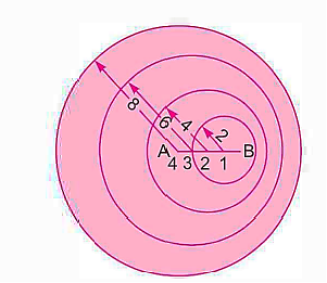
When a disturbance occurs in a compressible fluid, the disturbance propagates at the speed of sound in all directions (i.e., equal to C). The Mach number determines the nature of the disturbance's propagation. Consider a little projectile travelling in a stationary fluid from left to right in a straight line. The perturbations in the fluid will be caused by the movement of the projectile. With a velocity of C, this disturbance will move in all directions.
Case 1: Sub sonic flow


Let, V =1 Unit & C =2 Unit
Allow the missile to start at A and move to the right. Allow 4 seconds for the missile to reach position B. The point 4 is also noted at A. The points 3, 2, 1 and B, respectively, depict the position of the bullet after 1 sec, 2 sec, 3 sec, and 4 sec along the lines.


The disturbance created at A in 4 seconds will move a distance

Disturbance after 4 seconds. When the projectile is at point 3, it will reach B in three seconds and distance,

But the disturbance created at point 3 in three seconds will move a distance having a radius,

Similarly at point 2, the disturbance will have a radius

At point 1, the disturbance will have a radius

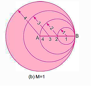
Case 2: Sonic flow


Let, V =1 Unit & C =1 Unit
Let the projectile moves from A to B in 4 seconds. The disturbance created at A in 4 seconds will move a distance having radius

The projectile from point 3 will move to position B in three seconds. The disturbance created at point 3, will move a distance having radius

Similarly, at the point 2 and point 1, the disturbance created at these points will move a distance having radius 2 and 1 in all directions respectively.
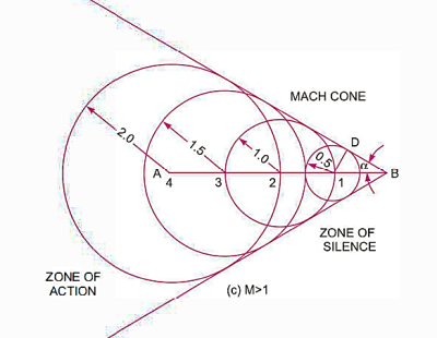
Case 3: Supersonic flow


Let the projectile moves from A to B in 4 seconds. The distance travelled by the projectile in 4 seconds

Hence, take AB = 4 units. The disturbance created at A will move in all directions and in 4 seconds, the radius of disturbance will be equal to

Hence taking A as centre, draw a circle with radius equal to 2 units. After one second from A, the projectile will be at point 3 and distance A3

The projectile from point 3 will reach point B in three seconds. Hence the disturbance created at point 3 will move in all directions and in three seconds, the radius of disturbance from point 3 will be equal to 3 x C = 3 x 0.5 = 1.5 units. Similarly, the radius of disturbance at point 2 and 1 will be


In this situation, the disturbance propagation sphere is always behind the projectile. We may construct a cone with a vertex at B by drawing a tangent to the separate circles that represent the propagating spherical waves on both sides. Mach Cone is the name given to this cone.
Mac Angle:
Half of Mach Cone

Zone of Action:

The effect of the disturbance is felt only in the region
Inside the Mach cone. This region is called the zone of action.
Zone of Silence:

There is no effect of disturbance in the region outside
The mach cone. The region which is outside the mach cone is called zone of silence.
Pressure waves are created by a disturbance in a fluid. These pressure waves travel in all directions at the speed of sound waves. However, a one-dimensional scenario will be explored for the purpose of simplicity. The model for one-dimensional pressure wave propagation is shown in the diagram below. It's a piston-equipped right-long pipe with a uniform cross-sectional area. Fill the pipe with a compressible fluid that is initially at rest. The piston moves to the right, causing a disruption in the fluid. This disturbance takes the shape of a pressure wave that moves through the fluid at the speed of sound.
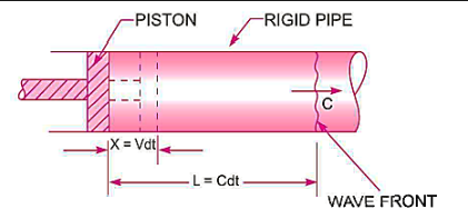
Distance travelled by the piston in time dt,

Distance travelled by the pressure wave in time dt

Pressure after compression,

Density after compression or the density of fluid in the length (L - x),

Now mass of fluid for a length 'L' before compression,


Mass of fluid after compression for length (L - x)


But,
Mass of fluid before compression = Mass of fluid after compression


Dividing by,


But the velocity of the piston, V, is very small as compared to the velocity of the pressure wave C. Also, the value of dp is very small.

If the piston is moved,
Net force on the fluid = Rate of change of momentum


So,


Key Takeaway:

Mach number has been defined as the square root of the ratio of the inertia force of a flowing fluid to the elastic force.


Thus, Mac number,

Mach number is an important non-dimensional metric in compressible fluid flow. The flow is defined as follows based on the Mach number:
- Sub sonic flow


- Sonic flow


- Supersonic flow


Key Takeaway:

The values of pressure, temperature, and density at a location on the body where a fluid is flowing past an immersed body and the consequent velocity becomes zero are known as stagnation qualities. The point is known as the point of stagnation. The pressure, density, and temperature measurements are referred to as stagnation pressure, density, and temperature, respectively.
- Stagnation Pressure

Applying Bernoulli's equation for adiabatic flow,

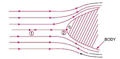


Point 2 is a stagnation point,


As,


So,

As,

So,

- Stagnation Density


As,

So,

- Stagnation Temperature

As,


As,


So,

Key Takeaway:

 o,
o,

Examples
Q.1. A pipe of diameter 300mm diameter suddenly converges t 150mm diameter, due to this the pressure changes from 95 kN/m² to 50 kN/m², if coefficient of contraction I 0.65, calculate the flow rate carried by the pipe.
Solution:
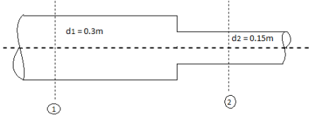
d=300 mm = 0.3m,
d₂ = 150 mm = 0.15m.
P₁ = 95 kN/m², P₂ = 50 kN/m², Cc = 0.65
To find: Q


By continuity equation


Loss due to sudden contraction

By Bernoulli’s equation

Z1= Z2


Discharge

Q.2. Three pipes of diameter 10 cm each, and having length 25 m, 50 m and 25 m are joined together in series. Water flows through this pipe at 2.15 m/s. The central pipe of length 50 m is replaced by 20 cm diameter pipe. The change in section due to replacement at both ends is sudden. Assuming friction factor f-0.032 and Cc is 0.62, find the net saving in head
Solution:
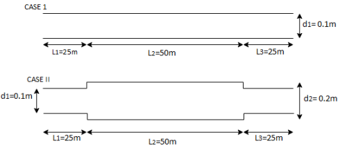
Three pipes of diameter d, 10 cm = 0.1 m=d,
L₁25 m, L=50 m, L=25 m. V₁ = 2.15 m/s V,
Central pipe L50 cm replaced by d, = 20 cm = 0.2 m.
f=0.032, C-0.62
To find: 1) Net saving in head.
Area

 0.031416 m
Discharge


Case I
Head loss due to friction (Considering total length)

Case II
Head loss= [ head loss due to friction] + [Head loss due sudden expansion]+[ Head loss due to friction] + [Head loss due to contraction] + [Head loss due friction]


Net saving in head = [head lost] case I –[ head lost] case II
= 7.5392-4.1084 = 3.4308 m
Q.3. A 50m long pipe of 10cm diameter carries water at a velocity 5m/s it has been decided to replace 25m of above pipe by enlarged diameter pipe of 20cm, the change of section being sudden, assuming f= 0.02 and coefficient of contraction Cc=0.62, find saving in the loss due to replacement of pipe.
Solution:
L=50 m, L₁= L = 25 m. Cc = 0.62,
f = 0.02 d=10 cm = 0.1 m,
d, = 20 cm = 0.2 m, d₂ = 0.1 m
To find: Saving head loss
(1) Head loss in initial pipe of L=50 m
Area


2) Head lost due to sudden contraction:

Using continuity equation


Head loss due friction


Total head loss = head loss due to friction + head loss due to contraction

Solving in head loss


Q.4. Two reservoirs at different elevations are connected with a compound pipe of 1 km total length; consisting of two sections. First section connect to higher level reservoir is 500 m long and 200 mm in a diameter and other half is connected to lower-level reservoir and has 100 mm diameter. Darcy Weisbach friction factors for the pipes are 0.019 and 0.02 respectively. If velocity of flow of water in the second section is 1.5 m/s. Find the difference in water levels in the reservoirs considering all losses. Find the rate of flow of water also. Find diameter of single uniform diameter pipe replace the above pipeline to carry same discharge. Take f = 0.018 for the pipe.
Solution:
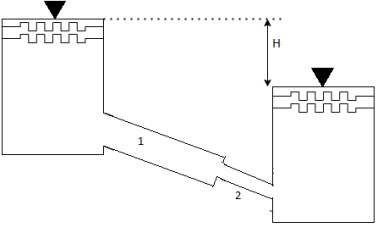
d₁= 200 mm = 0.2 m
f₁ = 0.019 d₂ = 100 mm = 0.1 m
f₂ = 0.02
L = 1 km
By continuity equation,
A₁V₁ = A₂V₂


Case I:
Major losses = Loss due to friction Loss due to friction in pipe 1 in pipe 2


Minor losses = Loss at entry + Loss due to contraction + loss at exit


Total losses = Major losses+ Minor losses

Case II: New pipe with uniform diameter.


The diameter of single equivalent pipe is 114.16 mm.
Q.5. The difference in water level, between two tanks which are connected by three pipes in series is 15 m. Length and diameter of these pipes are 300 m, 150 m, 200 m and 30 cm, 20 cm, 30 cm respectively. Find the discharge through the pipeline and tabulate all losses if f for the three pipes to be taken as 0.02, 0.025 and 0.03.
Solution:
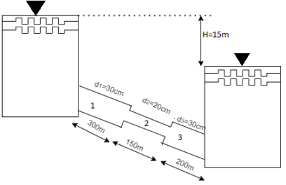
H=15 cm, d,= 30 cm = 03 m. f = 0.02
L₁= 300 m. d2 = 20 cm = 0.2 m.
F= 0.025,
L = 150 m,
d3 = 30 cm=0.3 m.
f = 0.03,
L = 200 m
Let V. V, and V, are the velocities in the 1", 2, and 3 pipe.
By continuity equation,


Case 1: Major Losses-Frictional loss in pipe 1+ Frictional loss in pipe 2+ Frictional loss in pipe 3

Put value we get,

Minor losses = loss at entry + loss due to contraction between pipe 1 and 2 + loss due to expansion between pipe 2 and 3 + loss at exit


Total loss = major losses + minor losses


Rate of flow of water

Q.6. Three pipes 300 m, 150 m, 200 m long having diameters 300 mm, 200 mm and 250 mm respectively are connected in a series in the same order. Pipe having 300 mm diameter in connected to the reservoir. Water level in the reservoir is 15 m above the pipe are 0.018, 0.02 and 0.019. Determine the flow rate, magnitude of loss in each pipe section, and the diameter when the three pipes are replaced by a single pipe (f = 0.016) to give the same discharge. Neglect the minor losses.
Solution:
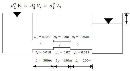
Let V, V, and V, are the velocities in the pipe 1, 2, 3 respectively.
By continuity equation


Major loss = hf1+hf2+hf3


Flow rate

Head loss in each pipe


Diameter when three pipes are replaced by single pipe
Using Dupit’s equation


Q.7. Three pipe: 300 m long, 30 cm diameter; 150 m long, 20 cm diameter; 200 m long, 25 cm diameter; are connected in series in the same order between two reservoirs. Darcy Weisbach friction factors for the three pipes are 0.018, 0.02 and 0.019 respectively. Determine the flow rate, if the difference of elevations of water levels in the two reservoirs is 15 m. Account for all losses: contractions and expansions are suddenly. Also determine magnitude of each loss in flow between the reservoirs. Use the given table. Loss coefficient for sudden contraction:
Ag/A1 | 0.2 | 0.3 | 0.4 | 0.5 | 0.6 | 0.7 |
K | 0.41 | 0.36 | 0.3 | 0.24 | 0.18 | 0.12 |
If the three pipes are replaced by a single pipe (f = 0.016 to give the same discharge), determine the diameter of pipe.
Solution:
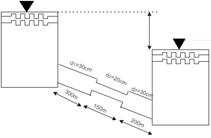
L₁ = 300 m,
f₁ = 0.018,
L₂=150 m. f₂ = 0.0,2
L₁ = 200 m, f = 0.019
d₁ = 30 cm = 0.3 m,
d₂ = 20 cm = 0.2 m, d3 = 25 cm = 0.25 m.
Major losses = Frictional loss in pipe 1 + Frictional loss in pipe 2+ Frictional loss in pipe 3


Case I
Minor losses= loss due to entrance + loss due to contraction + loss due to expansion+ loss due to exit

By continuity equation


The value K is calculated by interpolation method

Put the value V1, V2 and V3 and K in equation of minor losses


Now magnitude
Major loss


Minor loss
- Loss due to entrance

2. Loss due to contraction

3. Loss due to expansion

4. Loss due to exit

Case II
Diameter when the compound pipe is replaced by a single pipe


The diameter of new pipe i2 22.62 m
Q.8. Two pipes running parallel are joined end to end the total discharge to be carried by the system is 2000 liter/sec Determine the discharge carried by each pipe particular of pipes are as follows:
Pipe | Friction factor | Diameter | Length |
A | 0.018 | 0.60 | 1000 |
B | 0.020 | 0.80 | 800 |
Solution:
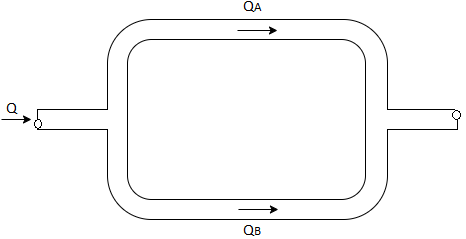
Q= 2000 liter/sec
For parallel pipe


Discharge through pipe A


The discharge through pipe


Q.9. Two pipes of 20cm and 30 cm diameter are laid in parallel to pass a total discharge of100 l.p.s. Each pipe is 250 m long. Determine discharge through each pipe. Now these pipes are connected in series to connect two tanks 500 m apart to carry same total discharge. Determine water level difference between the tanks neglect minor losses in both cases. Take f=0.02 for both pipes
Solution:
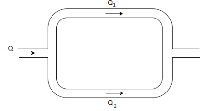
d1= 20cm= 0.2 m
d2 = 30cm= 0.3 m
Q= 100lps= 0.1 m^3/sec
L = 250 m
f = 0.02 for both pipes
To find: H
Case I
For parallel pipe head loss remain same in both pipes


For parallel pipe


Discharge


Case II
For pipe in series


Water level difference between tanks is 14.61 m
References:
- Fluid Mechanics and Hydraulic Machines by R.K. Bansal, Laxmi Publications
- Fluid Mechanics: Fundamentals and Applications by Y. A. Çengel and J. M. Cimbala, by McGraw-Hill
- Fluid Mechanics by Frank .M. White, mcgraw Hill Publishing Company Ltd.
- Fundamentals of Fluid Mechanics by munson, Wiley India Pvt. Ltd