Unit - 7
Thermodynamic cycles
The Rankine cycle is the basic operating cycle of all power plants, in which an operating fluid is continuously evaporated and condensed. The operating fluid chosen is primarily determined by the temperature range available.
- Isobaric heat transfer
The feed pump sends high-pressure liquid into the boiler, which heats it to saturation temperature. The addition of more energy causes the liquid to evaporate until it is completely converted to saturated steam.
- Isentropic expansion
The vapour expands in the turbine, creating work that can be converted to electricity. In practise, the expansion is limited by the cooling medium's temperature and the erosion of the turbine blades caused by liquid entrainment in the vapour stream as the process progresses into the two-phase region. The quality of the exit vapour should be greater than 90%.
- Isobaric heat rejection
The vapor-liquid mixture that exits the turbine is condensed at low pressure, typically in a surface condenser that uses cooling water. The pressure of the vapour in well-designed and maintained condensers is well below atmospheric pressure, approaching the saturation pressure of the operating fluid at the cooling water temperature.
- Isentropic compression
The feed pump raises the pressure of the condensate. Because liquids have a low specific volume, the pump work is relatively small and is frequently overlooked in thermodynamic calculations.
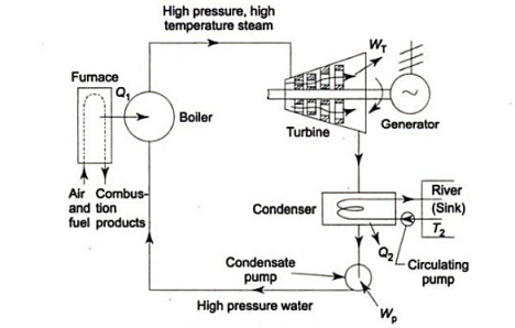
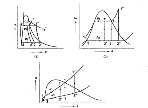
- h4+ Q1 = h1
Q1=h1-h4
- h1= WT+h2
WT = h1 -h2
- h2= Q2 + h3
Q2 =h2-h3
- h3 + Wp = h4
Wp = h4 -h3


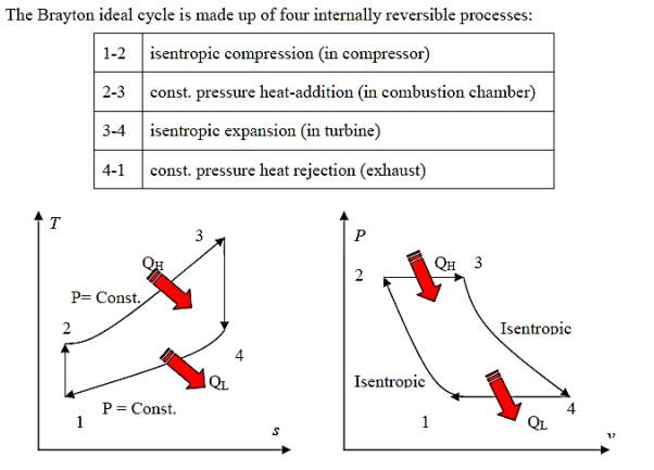
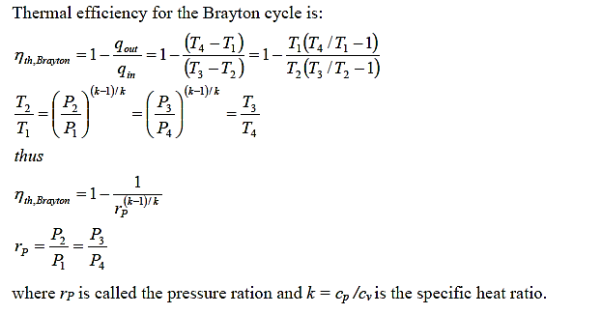
The Brayton cycle (also known as the Joule cycle) simulates the operation of a gas turbine engine. The cycle is made up of four stages.
- a - b Adiabatic, quasi-static (or reversible) compression in the inlet and compressor.
- b - c Constant pressure fuel combustion (idealized as constant pressure heat addition);
- c - d Adiabatic, quasi-static (or reversible) expansion in the turbine and exhaust nozzle, with which we
Take some work out of the air and use it to drive the compressor,
Take the remaining work out and use it to accelerate fluid for jet propulsion, or to turn a generator for electrical power generation.
- d - a Cool the air at constant pressure back to its initial condition

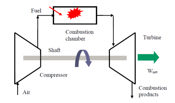
At room temperature, fresh air enters the compressor, where its pressure and temperature are raised.
High-pressure air enters the combustion chamber, where the fuel burns at a constant pressure.
The hot (and high-pressure) gas enters the turbine, where it expands to ambient pressure and generates work.
A gas turbine is a type of engine that is utilised in aircraft propulsion and electric power generation.
High thermal efficiency of up to 44%.
Suitable for use in mixed cycles (with steam power plant)
Great power-to-weight ratio, high dependability, and extended life
Fast start-up time of roughly 2 minutes, compared to 4 hours for steam-propulsion systems; high back work ratio (ratio of compressor work to turbine work), up to 50%, compared to a few percent in steam power plants.
The vapor-compression refrigeration is the most widely used cycle for refrigerators, air-conditioners, and heat pumps.
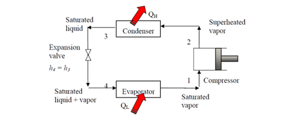
Assumptions for ideal vapor-compression cycle:
• all irreversibility’s in the evaporator, condenser, and compressor are ignored; and there are no frictional pressure drops.
• The refrigerant flows through the two heat exchangers at constant pressure (evaporator and condenser)
• heat losses to the environment are ignored
• The compression process is isotropic.
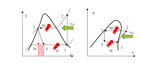
• A reversible, adiabatic (isentropic) compression of the refrigerant. The saturated vapor at state 1 is superheated to state 2.
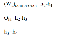
Wc =h2 − h1
• An internally reversible, constant-pressure heat rejection process in which the working substance is de-superheated and then condensed to a saturated liquid at 3. The working substance rejects the majority of its energy to the condenser cooling water during this process.
QH = h2 − h3
• An irreversible throttling process in which temperature and pressure decrease while maintaining constant enthalpy. At state 4, the refrigerant enters the evaporator as a low-quality saturated mixture.
h3 = h4
• An internal, reversible, constant-pressure heat interaction in which the refrigerant (two-phase mixture) evaporates to a saturated vapour at state point 1. The refrigerated space surrounding the evaporator provides the latent enthalpy required for evaporation. The refrigeration load is the amount of heat transferred to the working fluid in the evaporator.
QL = h1 − h4
Because throttling is an irreversible process, the ideal compression refrigeration cycle is not an internally reversible cycle.
The refrigerant would enter the evaporator at state 4s if the expansion valve (throttling device) was replaced by an isentropic turbine. As a result, the refrigeration capacity (area under 4-4s) would increase while the net work input would decrease (turbine will produce some work). However, due to the added cost and complexity, replacing the expansion valve with a turbine is not feasible.
The COP increases by 2 to 4% for every °C increase in evaporating temperature or decrease in condensing temperature.
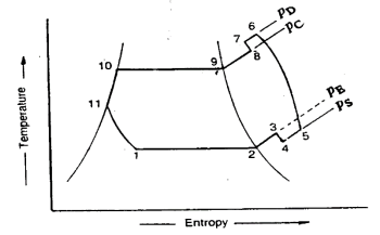
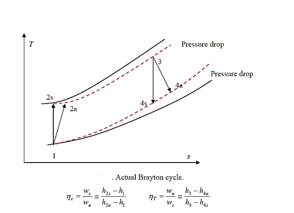
In many ways, the actual vapour compression cycle differs from the theoretical vapour compression cycle, some of which are unavoidable and result in losses. The following are the main differences between the theoretical and actual cycles:
- The vapour refrigerant that exits the evaporator is superheated.
- Refrigeration compression is neither isentropic nor polytropic.
- The condenser sub-cools the liquid refrigerant before it enters the expansion valve.
- The pressure in the evaporator and condenser drops.
The actual vapour compression cycle on T-s diagram is shown. The various processes are discussed below
(a) Process 1-2-3: The flow of refrigerant in the evaporator is depicted in this process. The entry of refrigerant into the evaporator is represented by point 1, and the exit of refrigerant from the evaporator in a superheated state is represented by point 3. Point 3 also represents the entry of superheated refrigerant into the compressor. It is possible that the superheating of vapour refrigerant from point 2 to point 3 is caused by
• Automatic control of the expansion valve so that the superheated vapour of the refrigerant exits the evaporator.
• Obtaining a greater amount of heat from the evaporator via pipes located within the cooled space.
• Heat is picked up from the suction pipe, which connects the evaporator delivery and the compressor suction valve.
The refrigerating effect and compressor work are increased in the first and second cases of superheating the vapour refrigerant. When compared to a saturation cycle at the same suction pressure, the coefficient of performance may be greater, less, or unchanged. Superheating also increases the required displacement of the compressor as well as the load on the compressor and condenser. This is denoted by 2-3 on the T-s diagram.
(b) Process 3-4-5-6-7-8: The flow of refrigerant through the compressor is represented by this process. Because of frictional resistance to flow, when the refrigerant enters the compressor through the suction valve at point 3, the pressure drops to point 4. As a result, the suction pressure (Ps) is less than the evaporator pressure (Pe). The temperature of the cold refrigerant vapour rises to point 5 during suction and prior to compression when it comes into contact with the compressor cylinder walls. 5-6 depicts the actual compression of the refrigerant, which is neither isentropic nor polytropic. This is due to heat transfer between the cylinder walls and the refrigerant vapour.
The temperature of the cylinder walls is somewhere between that of the cold suction vapour refrigerant and that of the hot discharge vapour refrigerant. The heat absorbed by the vapour refrigerant from the cylinder walls during the first part of the compression stroke can be assumed to be equal to the heat rejected by the vapour refrigerant to the cylinder walls. The cooling effect at discharge is similar to the heating effect at suction, as shown in 4-5. At constant pressure, these heating and cooling effects occur. There is a pressure drop due to the frictional resistance of flow, i.e., the actual discharge pressure (Pd) is greater than the condenser pressure (Pc).
(c) Process 8-9-10-11: The flow of refrigerant through the condenser is represented by this process. The cooling of superheated vapour refrigerant to the dry saturated state is represented by process 8-9. The removal of latent heat in process 9-10 converts the dry saturated refrigerant to liquid refrigerant. The sub-cooling of liquid refrigerant in the condenser before passing through the expansion valve is represented by processes 10-11.
This is advantageous because it increases the refrigerating effect per kg of refrigerant flow. It also reduces the volume of refrigerant partially evaporated from liquid refrigerant as it passes through the expansion valve. Large amounts of circulating cooling water at temperatures much lower than condensing temperatures can be used to increase the refrigerating effect.
(d) Process 11-1: Throttling from the condenser pressure to the evaporator pressure represents the expansion of subcooled liquid refrigerant
Effect of Suction Pressure
In the previous article, we discussed how, in practise, the suction pressure (or evaporator pressure) decreases due to the frictional resistance of the refrigerant flow. Consider a hypothetical vapour compression cycle 1'-2'-3-4' in which the suction pressure decreases from ps to ps' as shown on the p-h diagram. It should be noted that the decrease in suction pressure is significant.
- Decreases the refrigerating effect from (h1 - h4) to (h1'- h4') and
- Increases the work required for compression from (h2 – h1) to (h2' – h1')
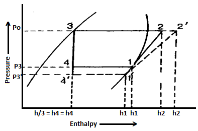
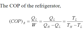
Because the C.O.P. Of the system is the ratio of refrigerating effect to work done, lowering the suction pressure has the net effect of lowering the C.O.P. Of the refrigerating system for the same amount of refrigerant flow. As a result of the decrease in suction pressure, the system's refrigerating capacity decreases, and the refrigeration cost increases.
Effect of Discharge Pressure
We have already discussed how, in practise, the discharge pressure (or condenser pressure) rises due to the frictional resistance of the refrigerant flow. Consider a theoretical vapour compression cycle 1-2'-3'-4' in which the discharge pressure rises from Pd to Pd' as shown on the p-h diagram
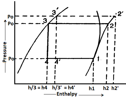
It may be noted that the increase in discharge pressure:
- Decreases the refrigerating effect from (h1 - h4) to (h1 - h4')
- Increases the work required for compression from (h2-h1) to (h2' - h1)
From above, we can see that an increase in discharge pressure has the same effect as a decrease in suction pressure. However, an increase in discharge pressure has a less severe effect on the system's refrigerating capacity than a decrease in suction pressure.
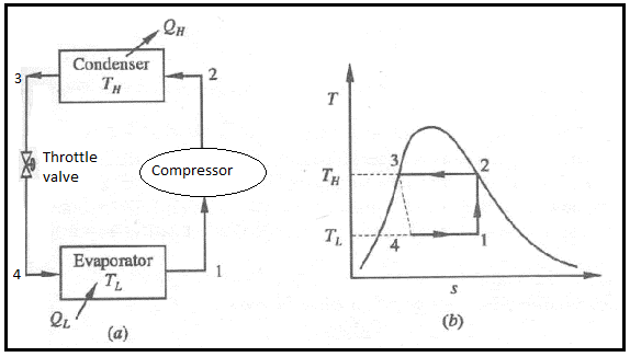
Vapour compression refrigeration system analysis:
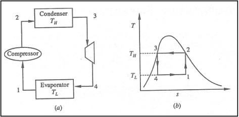
• 1-2: Isentropic compression from state 1 (wet vapour) to state 2 (saturated vapour)
• 2-3: Heat rejection (QH) in the condenser
• 3-4: Isentropic expansion from state 3 (saturated liquid)
• 4-1: Heat absorption (QL) in the evaporator


References:
- Basic and Applied Thermodynamics by PK Nag, MCGRAW HILL INDIA.
- Thermodynamics for Engineers by Kroos & Potter, Cengage Learning.
- Thermodynamics by Shavit and Gutfinger, CRC Press.
- Thermodynamics- An Engineering Approach by Cengel, MCGRAW HILL INDIA.
- Basic Engineering Thermodynamics, Joel, Pearson.