Unit - 4
Basics of Compressible Flow
Stagnation Properties of a fluid is defined as "When a flowing fluid past an immersed body, and at a point on the boy if the resultant velocity becomes zero, then the values of pressure, temperature and density at that point are called as stagnation properties. That point is called as stagnation point.
In thermodynamics and fluid mechanics, stagnation temperature is the temperature at a stagnation point in a fluid flow. At a stagnation point the speed of the fluid is zero and all of the kinetic energy has been converted to internal energy and is added to the local static enthalpy.
The 'stagnation pressure' is the pressure that the fluid would obtain if brought to rest without loss of mechanical energy.
Isentropic flows occur when the change in flow variables is small and gradual, such as the ideal flow through the nozzle shown above. The generation of sound waves is an isentropic process. A supersonic flow that is turned while the flow area increases is also isentropic or converging-diverging nozzles are found in steam or gas turbine and aircraft or spacecraft propulsion systems.
In this system we consider the effect of back pressure that is the pressure applied at the nozzle discharge region on the exit velocity, the mass flow rate and the pressure distribution along the nozzle.
Converging Nozzle:

Maximum mass flow rate:

M= Mach Number
R= Universal Gas Constant,
T=Temperature
K= specific heat ratio
A= Area
P= Pressure
M dot= Mass flow rate
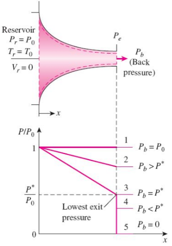
The effect of back pressure on the pressure distribution along a converging nozzle.
Choked Flow” is a fluid dynamic condition associated with the venturi effect.Fluid flow through a restricted area whose rate reaches a maximum when the fluid velocity reaches the sonic velocity at some point along the flow path. The phenomenon of choking exists only in compressible flow and can occur in several flow situations.
Consider a fluid (liquid/gas) flowing through a venturi or a convergent-divergent nozzle as shown below.
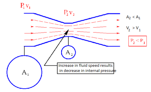
Fig. Choked flow
Assume that P1 is constant. As the fluid travels through the “constriction”, its velocity increases (according to conservation of mass principle). Simultaneously, the static pressure of the fluid P2 decreases. This is a well-established principle.
Now, let us increase the mass flow rate of the fluid entering the venturi while keeping P1 constant. This will lead to increase in velocity v1. This will also increase the velocity v2 at the exit of the constriction.
Now, keep on increasing the mass flow rate of the fluid gradually while keeping P1 constant. You will always notice that both v1 and v2 increase gradually; but this works only up to a certain mass flow rate. After this point, increasing the mass flow rate without changing the pressure P1 is not possible. Thus, the mass flow rate has reached its limiting value. This condition is called as “Choked Flow”. The mass flow rate at choking point depends on the pressure and temperature of the fluid entering the venturi/nozzle. Usually choking occurs when the exit velocity v2 of the fluid reaches the speed of Mach 1.
Choked flow can occur through a convergent flow area or nozzle attached to a huge reservoir. Flow exits the reservoir through the nozzle if the back pressure is less than the reservoir pressure. When the back pressure is decreased slightly below the reservoir pressure, a signal from beyond the nozzle exit is transmitted at sonic speed to the reservoir.
The reservoir responds by sending fluid through the nozzle. Further, the maximum velocity of the fluid exists at the nozzle throat where the area is smallest. When the back pressure is further decreased, fluid exits the reservoir more rapidly. Eventually, however, the velocity at the throat reaches the sonic velocity. Then the fluid velocity at the throat is sonic, and the velocity of the signal is also sonic. Therefore, further decreases in back pressure are not sensed by the reservoir, and correspondingly will not induce any greater flow to exit the reservoir. The nozzle is thus said to be choked, and the mass flow of fluid is a maximum.
Going on with gas flow and leaving liquid flow aside, we may notice that M=1 can only occur in a nozzle neck, either in a smooth throat where dA=0, or in a singular throat with discontinuous area slope (a kink in nozzle profile, or the end of a nozzle). Naming with a '*' variables the stage where M=1 (i.e. the sonic section, which may be a real throat within the nozzle or at some extrapolated imaginary throat downstream of a subsonic nozzle), equations are:


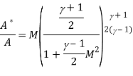
Where the expressions for total temperature Tt and total pressure pt has been substituted to show that temperature and pressure at the throat (also known as critical values), are just a function of γ, since, for isentropic flows, total conditions do not change along the stream. Although the equations above apply to all 1D isentropic perfect-gas flows.
Key Takeaways:
1) Choked Flow” is a fluid dynamic condition associated with the venturi effect.
2) Choked flow can occur through a convergent flow area or nozzle attached to a huge reservoir.
Subsonic Flow: When Mach number is less than 1.0 or V is less than C, then the flow is called Subsonic Flow.
Supersonic Flow: When Mach number is greater than 1.0 or V is greater than C, then the flow is called Supersonic Flow.
It is a completely irreversible process takes place in the Convergent divergent type of nozzles (or in venturi) at the divergent section. A sudden change in pressure, temperature, and flow velocity takes place while supersonic flow was taking place. After shock flow becomes subsonic and stays subsonic till end. Width of this shock is very less i.e. about 4 times the mean free path of the gas molecules.
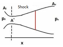
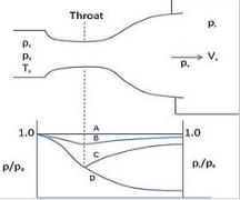
Fig. Shock
m= mass flow rate
V= velocity
ρ= density
γ= specific heat ratio
A= area
M= Mach number
a= speed of sound
p-Difference in pressures on body
V-velocity of fluid surrounding the body
g-Acceleration due to gravity
z-height of body
po - stagnation pressure
pc - back pressure
A - Area at exit of nozzle
A*- Area at throat
Conservation of mass:
m=
ρx V x A
Conservation of momentum:
Ρ x V x dV = -d

Isentropic steady flow:

Bernoulli's principle:


Figure shows the flow through the nozzle when it is completely subsonic (i.e. the nozzle isn't choked). The flow accelerates out of the chamber through the converging section, reaching its maximum (subsonic) speed at the throat. The flow then decelerates through the diverging section and exhausts into the ambient as a subsonic jet. Lowering the back pressure in this state increases the flow speed everywhere in the nozzle.
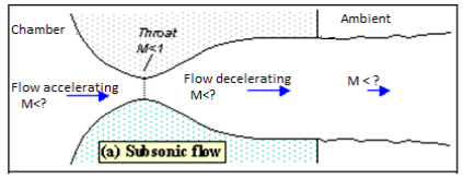
Fig. Subsonic flow
Lower it far enough and we eventually get to the situation shown in figure 2. The flow pattern is exactly the same as in subsonic flow, except that the flow speed at the throat has just reached Mach 1. Flow through the nozzle is now choked since further reductions in the back pressure can't move the point of M=1 away from the throat. However, the flow pattern in the diverging section does change as you lower the back pressure further.
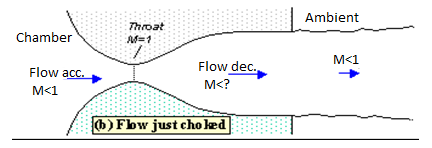
Fig. Flow just choked
As pb is lowered below that needed to just choke the flow a region of supersonic flow forms just downstream of the throat. Unlike a subsonic flow, the supersonic flow accelerates as the area gets bigger. This region of supersonic acceleration is terminated by a normal shock wave. The shock wave produces a near-instantaneous deceleration of the flow to subsonic speed. This subsonic flow then decelerates through the remainder of the diverging section and exhausts as a subsonic jet. In this regime if you lower or raise the back pressure you increase or decrease the length of supersonic flow in the diverging section before the shock wave.
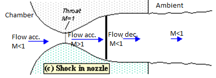
Fig. Shock in nozzle
If you lower pb enough you can extend the supersonic region all the way down the nozzle until the shock is sitting at the nozzle exit (figure 4). Because you have a very long region of acceleration (the entire nozzle length) in this case the flow speed just before the shock will be very large in this case. However, after the shock the flow in the jet will still be subsonic.
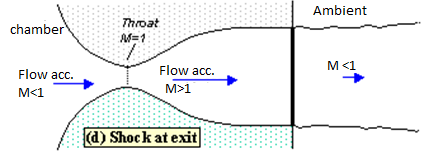
Fig. Shock at exit
Lowering the back pressure further causes the shock to bend out into the jet (figure 5), and a complex pattern of shocks and reflections is set up in the jet which will now involve a mixture of subsonic and supersonic flow, or (if the back pressure is low enough) just supersonic flow. Because the shock is no longer perpendicular to the flow near the nozzle walls, it deflects it inward as it leaves the exit producing an initially contracting jet. We refer to this as over expanded flow because in this case the pressure at the nozzle exit is lower than that in the ambient (the back pressure)- i.e. the flow has been expanded by the nozzle to much.
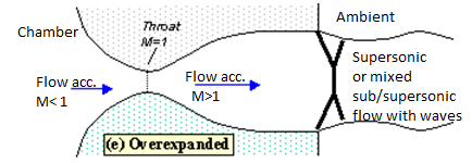
Fig. Overexpanded
A further lowering of the back pressure changes and weakens the wave pattern in the jet. Eventually we will have lowered the back pressure enough so that it is now equal to the pressure at the nozzle exit. In this case, the waves in the jet disappear altogether (figure 6), and the jet will be uniformly supersonic. This situation, since it is often desirable, is referred to as the 'design condition'.

Fig Design condition
Finally, if we lower the back pressure even further we will create a new imbalance between the exit and back pressures (exit pressure greater than back pressure), figure 7. In this situation (called 'under expanded') what we call expansion waves (that produce gradual turning and acceleration in the jet) form at the nozzle exit, initially turning the flow at the jet edges outward in a plume and setting up a different type of complex wave pattern.
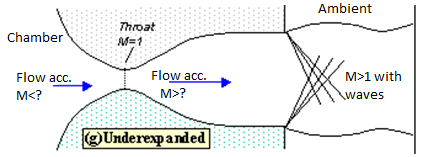
Fig. Under expanded
Key Takeaways:
1) When the flow accelerates (sub or supersonically) the pressure drops The pressure rises instantaneously across a shock
2) The pressure falls across an expansion wave
3) Mach number: It is the ratio of speed of flow in a medium to the speed of sound in that medium
In thermodynamics, an isentropic process is an idealized thermodynamic process that is both adiabatic and reversible. The work transfers of the system are frictionless, and there is no transfer of heat or matter. Such an idealized process is useful in engineering as a model of and basis of comparison for real processes.[7] This is idealized as reversible processes do not occur in reality; thinking of a process as both adiabatic and reversible would show that the initial and final entropies are the same, thus, the reason it is called isentropic (entropy does not change). Thermodynamic processes are named based on the effect they would have on the system (ex. Isovolumetric: constant volume, isenthalpic: constant enthalpy). Even though in reality it is not necessarily possible to carry out an isentropic process, some may be approximated as such.
The word "isentropic" can be interpreted in another way, since its meaning is deducible from its etymology. It means a process in which the entropy of the system remains unchanged, as mentioned this requires the process to be both adiabatic and reversible. However, this could also occur in a system where the work done on the system includes friction internal to the system, and heat is withdrawn from the system in just the right amount to compensate for the internal friction, so as to leave the entropy unchanged.[8] However, in relation to the universe, the entropy of the universe would increase as a result.
Given an upstream Mach number, M1, and the ratio of specific heats,  , the post normal shock Mach number, M2, can be calculated using the equation below.

The next equation shows the relationship between the post normal shock pressure P2 and the upstream ambient pressure, P1.

The relationship between the post normal shock density,  2 and the upstream ambient density,
  1.
1.

Next, the equation below shows the relationship between the post normal shock temperature, T2, and the upstream ambient temperature, T1.

Nozzles are actually used to modify the flow of a fluid (i.e. by increasing kinetic energy of the flow in expense of its pressure). Convergent-divergent type of nozzles are mostly used for supersonic flows because it is impossible to create supersonic flows (mach number more than one) in convergent type of nozzle and therefore it restricts us to a limited amount of mass flow through a particular nozzle. In convergent-divergent type of nozzles we can increase the flow velocity much higher than sonic velocity that is why these type of nozzles have a wide applications such as propelling nozzles in jet engines or in air intake for engines working at high rpms.
For understanding the working principle of convergent-divergent type of nozzles, first we need to look the working principle of only convergent type of nozzles. In these type of nozzles the area of the nozzle reduces gradually in the direction of flow. The pressure at intake is called stagnation pressure and the pressure at exit is called back pressure. The value of back pressure can never be more than 1 in case of a nozzle. As we start reducing the back pressure we observe that flow velocity and mass flow rate also starts increasing, but this will happen up to a certain limit, after which no increase in velocity or mass flow rate takes place. This situation is known as choked i.e. no further increase in mass flow rate takes place whatever be the back pressure now. This situation takes place at a particular mach number i.e. at mach number '1'.
But the case is not the same when we use a divergent nozzle just after the convergent. Actually the principle reverses i.e. when we attach a divergent nozzle just after the convergent nozzle our flow speed starts increasing with the decrease in back pressure and also the mass flow rate. And therefore in this type of nozzles we can reach to the speeds above sonic i.e. supersonic.
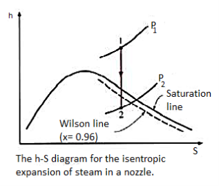
As steam expands in the nozzle, its pressure and temperature drop, and it is expected that the steam start condensing when it strikes the saturation line. But this is not always the case. Owing to the high velocities, the residence time of the steam in the nozzle is small, and there may not sufficient time for the necessary heat transfer and the formation of liquid droplets. Consequently, the condensation of steam is delayed for a little while. This phenomenon is known as super saturation, and the steam that exists in the wet region without containing any liquid is known as supersaturated steam.
The locus of points where condensation will take place regardless of the initial temperature and pressure at the nozzle entrance is called the Wilson line. The Wilson line lies between 4 and 5 percent moisture curves in the saturation region on the h-s diagram for steam, and is often approximated by the 4 percent moisture line. The super saturation phenomenon is shown on the h-s chart below:
4.9.1 Nozzle efficiency
In nozzle, the wall friction is small in convergent portion as compared to divergent portion. The friction losses in the nozzle depend upon the type of material, size, and shape, properties of the fluid and flow conditions is nozzle.
The nozzle efficiency can be defined as the ratio of actual enthalpy drop to ideal (isentropic) enthalpy drop in nozzle.
Therefore
Nozzle efficiency, ηn = (Actual enthalpy drop) / (isentropic enthalpy drop)
ηn = (h1 – h2) / (h1 – h'2
The nozzle efficiency can be defined as the ratio of actual enthalpy drop to isentropic enthalpy drop.
Nozzle Efficiency of Steam Turbine:
Nozzle efficiency of steam turbine is the ratio of energy supplied to the blades per kg of steam to the total energy supplied per stage per kg of steam.
The energy supplied to the blades per kg of steam

So, Nozzle Efficiency equation of steam turbine is

Efficiency of diffuser:
The efficiency of the diffuser is defined as the ratio of the enthalpy change that occurred between the entrance to exit stagnation pressure to the kinetic energy.

Where P1, U1, Al and P2, U2, A2 denote the pressure, velocity and area of cross-section at the entrance and exit sections of the diffuser, respectively, and  is the density of the fluid.
Another definition of diffuser efficiency used in design expresses it as the ratio of the difference of pressure between the entrance and exit sections to the dynamic pressure at the entrance: that is

Key takeaways:
1) The smallest cross-sectional area of the nozzle is called the throat of the nozzle.
2) Nozzle Efficiency equation of steam turbine

References:
1. Sonntag, R. E, Borgnakke, C. And Van Wylen, G. J., 2003, 6th Edition, Fundamentals of Thermodynamics, John Wiley and Sons.
2. Jones, J. B. And Duggan, R. E., 1996, Engineering Thermodynamics, Prentice-Hall of India
3. Moran, M. J. And Shapiro, H. N., 1999, Fundamentals of Engineering Thermodynamics, John Wiley and Sons.
4. Yunus A. Cengel; Michael A. Boles, Thermodynamics: An Engineering Approach, McGraw- Hill.
5. Nag, P.K, 1995, Engineering Thermodynamics, Tata McGraw-Hill Publishing Co. Ltd.