Unit - 5
Reciprocating Compressors
Principles on which compressors work:
A compressor is a mechanical device that increases the pressure of a gas by reducing its volume. (The fluid here is generally air since liquids are theoretically incompressible).
Classification of compressor:
There are mainly two types of Compressors-
- Reciprocating compressor
- Single stage
- Multi stage
2. Rotary compressor
Reciprocating compressor:
In a reciprocating compressor, a volume of gas is drawn into a cylinder, it is trapped, and compressed by piston and then discharged into the discharge line. The cylinder valves control the flow of gas through the cylinder and these valves act as check valves.
Reciprocating compressors can be Single acting or double acting.
Reciprocating compressor types:
- Single–Stage Reciprocating Compressor:
Compression is done in single stage or by single cylinder only and it is used for generation of low-pressure air.
2. Double–stage Reciprocating Compressor:
It is a compressor that produces highly pressurized air and mostly it is used nowadays in heavy duty mechanical devices.
Different parts of reciprocating compressor:
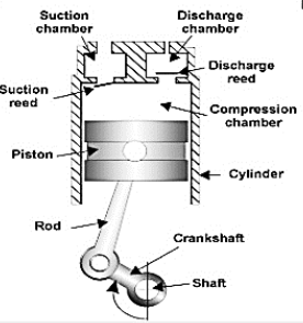
Figure1: Reciprocating compressor
- Suction valve.
- Suction Chamber.
- Piston & Piston Rod.
- Cylinder.
- Discharge valve.
- Discharge Chamber.
Principle of Operation:
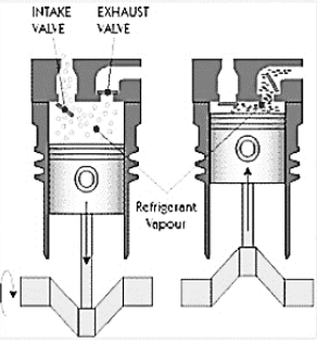
Figure 2: Operation of Reciprocating compressor
- Figure 2 shows single-acting piston actions in the cylinder of a reciprocating compressor.
- The piston is driven by a crank shaft via a connecting rod.
- At the top of the cylinder are a suction valve and a discharge valve.
- A reciprocating compressor usually has two, three, four, or six cylinders in it.
- As the piston travels toward the bottom dead center, the volume of the cylinder increases and due to the pressure difference the suction valve is opened.
- The pressure inside the cylinder is slightly less than suction line pressure. So, the volume of the gas starts increasing as the piston moves towards BDC.
- So, the piston continues its motion towards BDC till the area above piston in the cylinder become full of fluid (gas) & then the suction valve gets closed.
- Now when the crankshaft moves further and completes its revolution the piston also moves in opposite direction this time towards TDC.
- Now, again due to the Pressure difference between the delivery line and inside of the cylinder the delivery valves open in the delivery stroke.
- So, at point 3, the piston reaches the top dead center TDC.
- At top dead center, as the piston comes to a complete stop prior to reversing direction, the pressure across the valve is equal.
- So, the discharge valve is closed.
- At point 2, the pressure inside the cylinder has become slightly greater than discharge line pressure.
- This causes the valve opening allowing the gas to flow out of the cylinder.
- The volume continues to decrease toward point 3, maintaining a sufficient pressure difference across the discharge valve to hold it open.
- Now Again, as the piston moves towards BDC, the gas pressure inside the cylinder becomes less than the suction line pressure, so the suction valve opens again.
- The cycle then starts over again.
- The shape of the re-expansion line (Line 3-4) is dependent on the same compression exponent that determines the shape of the compression line.
Key takeaway:
- So, the discharge valve is closed.
- At point 2, the pressure inside the cylinder has become slightly greater than discharge line pressure.
- This causes the valve opening allowing the gas to flow out of the cylinder.
- The volume continues to decrease toward point 3, maintaining a sufficient pressure difference across the discharge valve to hold it open.
- Now Again, as the piston moves towards BDC, the gas pressure inside the cylinder becomes less than the suction line pressure, so the suction valve opens again.
- The cycle then starts over again.
Single Stage Reciprocating Air Compressor
Working Principle:
Here, pressure is increased by means of variation in the volume of cylinder obtained by a moving piston.
Construction:
- Single stage single acting air compressor consists of a piston, which reciprocates inside a cylinder having connecting rod and crank mechanism.
- There are inlet and delivery valves mounted in the head of cylinder.
- The inlet and delivery valves are of pressure differential type i.e.; they operate as a result of pressure difference across the valves.

Working:
Working of single stage reciprocating air compressor is completed in two strokes.
a). Suction Stroke:
- When the piston moves in the downward direction, from (T.D.C.) to (B.D.C), the air compressed in the previous compressions and entrapped in the clearance space begins to expand.
- Due to expansion, the pressure of air inside the cylinder starts to decrease.
- After some travel of piston from T.D.C. Towards B.D.C, the pressure of air inside the cylinder falls below the atmospheric pressure.
- Thus, due to pressure difference, the inlet valve gets opened. Now, the atmospheric air is sucked into the cylinder.
b). Compression Stroke:
- When the piston starts moving from BDC to TDC, the pressure of sucked air inside the cylinder begins to increase.
- When the pressure of air inside the cylinder increases above the atmospheric pressure, the inlet valve gets closed.
- Further movement of piston towards TDC causes compression of air sucked during suction stroke.
- Due to this, pressure of air inside the cylinder goes on increasing.
- As soon as, the pressure reaches up to desired discharge pressure, the delivery valve gets opened and compressed air is delivered into the receiver.
- Now again the piston starts moving from TDC to BDC, and the cycle is repeated again and again.
Two stage reciprocating compressor:

- Fig shows schematic arrangement of two stage reciprocating air compressor with water-cooled intercooler.
- It consists of a low-pressure cylinder & a high pressure cylinder.
- Fresh air is sucked from the atmosphere in low pressure cylinder during suction stroke at intake pressure P1& temperature T1.
- After compression in low pressure cylinder air is delivered to the intercooler at pressure P2& temperature T2.
- In intercooler air is cooled to temperature T3 at constant pressure P2.
- After intercooling air is admitted to high pressure cylinder, where it is compressed to pressure P3& temperature T3.
Key takeaway:
- In a single-stage compression, the pressure ratio is less. But sometimes we require a higher-pressure ratio. So, in order to get a large pressure ratio, we can employ a large pressure in a single cylinder or compress the air in two or more cylinders in series.
- There are some disadvantages of using a single-cylinder for employing a higher-pressure ratio: If we use a single-cylinder then the size of the cylinder will become too large, the final temperature of compressed air increases and the process no longer remains isothermal.
The optimal stage pressure ratio for a multi stage compression is calculated with well-known formula that assigns an equal ratio for all stages based on the hypotheses that all isentropic efficiencies are also equal.
For minimum power consumption in industrial applications, gases should ideally be cooled at the same time they are being compressed, maintaining their initial temperature as constant during the whole process. The increase in power consumption caused by compressing a gas that is progressively getting hotter, with large mass flows and long operating hours can be economically unstable.
It is given by,
r = 
Key Takeaways:
Important formula for optimal stage compression ratio is given as-
r = 
An intercooler is any mechanical device used to cool a fluid, including liquids or gases, between stages of a multi-stage heating process, typically a heat exchanger that removes waste heat in a gas compressor. They are used in many applications, including compressors, air conditioners, refrigerators, and gas turbines.
Effects of intercooling on Brayton cycle:
- Inter cooling means the removal of heat from compressed air between the stages of compression. It is known that the work input in compression is minimum if the compression process is isothermal.
- In order to achieve isothermal process compression is divided in number of stages and air is cooled between the stages with help of intercooler.
- The greater the number of stages of compression with intercooling between each stage, the closer will be the approximation to an isothermal process.
- The intercooler is a heat exchanger in which compressed air is cooled in order to reduce volume and increase density.
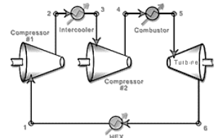

Figure 3: Intercooling on Brayton cycle
For ideal cycle with intercooling
Wc = C p (T 2a -T 1) + (T 2 -T 2b)
Heat supplied
Qs = C p (T 3 -T 2)
Work by turbine: W t =C p (T 3 -T 4)
Thermal efficiency of gas turbine cycle with intercooling:

Key takeaway:
- When the temperature of the air leaving the intercooler is equal to the original atmospheric air temperature, then this is known as known as Complete or Perfect Intercooling.
- When the temperature of the air leaving the intercooling is more than the original atmosphere air temperature, then this is known as incomplete or Imperfect Intercooling.
- Thermal efficiency of gas turbine cycle with intercooling:

Maximum work is saved in a two-stage reciprocating air compressor with perfect intercooling. Work required to be done by a two-stage reciprocating air-compressor with complete intercooling is given by-

If the intake pressure and delivery pressure are constant, then the least value of the intermediate or intercooler pressure may be obtained by differentiating the above equation with respect to intercooler pressure. At this value of intercooler pressure, the work required to drive the compressor is minimum.


Now considering  (a constant)


This is the condition of minimum work required for a two stage reciprocating air-compressor,
Now Substituting  in equation (1)


In, general for compressor having q number of stages,
Condition for minimum work required,

And minimum work required for compression,

Key takeaway:
- Work required to be done by a two-stage reciprocating air-compressor with complete intercooling is given by-

- Minimum power required for compression is given by-

References:
1. Sonntag, R. E, Borgnakke, C. And Van Wylen, G. J., 2003, 6th Edition, Fundamentals of Thermodynamics, John Wiley and Sons.
2. Jones, J. B. And Duggan, R. E., 1996, Engineering Thermodynamics, Prentice-Hall of India
3. Moran, M. J. And Shapiro, H. N., 1999, Fundamentals of Engineering Thermodynamics, John Wiley and Sons.
4. Yunus A. Cengel; Michael A. Boles, Thermodynamics: An Engineering Approach, McGraw- Hill.
5. Nag, P.K, 1995, Engineering Thermodynamics, Tata McGraw-Hill Publishing Co. Ltd.
Unit - 5
Reciprocating Compressors
Principles on which compressors work:
A compressor is a mechanical device that increases the pressure of a gas by reducing its volume. (The fluid here is generally air since liquids are theoretically incompressible).
Classification of compressor:
There are mainly two types of Compressors-
- Reciprocating compressor
- Single stage
- Multi stage
2. Rotary compressor
Reciprocating compressor:
In a reciprocating compressor, a volume of gas is drawn into a cylinder, it is trapped, and compressed by piston and then discharged into the discharge line. The cylinder valves control the flow of gas through the cylinder and these valves act as check valves.
Reciprocating compressors can be Single acting or double acting.
Reciprocating compressor types:
- Single–Stage Reciprocating Compressor:
Compression is done in single stage or by single cylinder only and it is used for generation of low-pressure air.
2. Double–stage Reciprocating Compressor:
It is a compressor that produces highly pressurized air and mostly it is used nowadays in heavy duty mechanical devices.
Different parts of reciprocating compressor:

Figure1: Reciprocating compressor
- Suction valve.
- Suction Chamber.
- Piston & Piston Rod.
- Cylinder.
- Discharge valve.
- Discharge Chamber.
Principle of Operation:
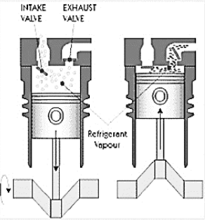
Figure 2: Operation of Reciprocating compressor
- Figure 2 shows single-acting piston actions in the cylinder of a reciprocating compressor.
- The piston is driven by a crank shaft via a connecting rod.
- At the top of the cylinder are a suction valve and a discharge valve.
- A reciprocating compressor usually has two, three, four, or six cylinders in it.
- As the piston travels toward the bottom dead center, the volume of the cylinder increases and due to the pressure difference the suction valve is opened.
- The pressure inside the cylinder is slightly less than suction line pressure. So, the volume of the gas starts increasing as the piston moves towards BDC.
- So, the piston continues its motion towards BDC till the area above piston in the cylinder become full of fluid (gas) & then the suction valve gets closed.
- Now when the crankshaft moves further and completes its revolution the piston also moves in opposite direction this time towards TDC.
- Now, again due to the Pressure difference between the delivery line and inside of the cylinder the delivery valves open in the delivery stroke.
- So, at point 3, the piston reaches the top dead center TDC.
- At top dead center, as the piston comes to a complete stop prior to reversing direction, the pressure across the valve is equal.
- So, the discharge valve is closed.
- At point 2, the pressure inside the cylinder has become slightly greater than discharge line pressure.
- This causes the valve opening allowing the gas to flow out of the cylinder.
- The volume continues to decrease toward point 3, maintaining a sufficient pressure difference across the discharge valve to hold it open.
- Now Again, as the piston moves towards BDC, the gas pressure inside the cylinder becomes less than the suction line pressure, so the suction valve opens again.
- The cycle then starts over again.
- The shape of the re-expansion line (Line 3-4) is dependent on the same compression exponent that determines the shape of the compression line.
Key takeaway:
- So, the discharge valve is closed.
- At point 2, the pressure inside the cylinder has become slightly greater than discharge line pressure.
- This causes the valve opening allowing the gas to flow out of the cylinder.
- The volume continues to decrease toward point 3, maintaining a sufficient pressure difference across the discharge valve to hold it open.
- Now Again, as the piston moves towards BDC, the gas pressure inside the cylinder becomes less than the suction line pressure, so the suction valve opens again.
- The cycle then starts over again.
Single Stage Reciprocating Air Compressor
Working Principle:
Here, pressure is increased by means of variation in the volume of cylinder obtained by a moving piston.
Construction:
- Single stage single acting air compressor consists of a piston, which reciprocates inside a cylinder having connecting rod and crank mechanism.
- There are inlet and delivery valves mounted in the head of cylinder.
- The inlet and delivery valves are of pressure differential type i.e.; they operate as a result of pressure difference across the valves.

Working:
Working of single stage reciprocating air compressor is completed in two strokes.
a). Suction Stroke:
- When the piston moves in the downward direction, from (T.D.C.) to (B.D.C), the air compressed in the previous compressions and entrapped in the clearance space begins to expand.
- Due to expansion, the pressure of air inside the cylinder starts to decrease.
- After some travel of piston from T.D.C. Towards B.D.C, the pressure of air inside the cylinder falls below the atmospheric pressure.
- Thus, due to pressure difference, the inlet valve gets opened. Now, the atmospheric air is sucked into the cylinder.
b). Compression Stroke:
- When the piston starts moving from BDC to TDC, the pressure of sucked air inside the cylinder begins to increase.
- When the pressure of air inside the cylinder increases above the atmospheric pressure, the inlet valve gets closed.
- Further movement of piston towards TDC causes compression of air sucked during suction stroke.
- Due to this, pressure of air inside the cylinder goes on increasing.
- As soon as, the pressure reaches up to desired discharge pressure, the delivery valve gets opened and compressed air is delivered into the receiver.
- Now again the piston starts moving from TDC to BDC, and the cycle is repeated again and again.
Two stage reciprocating compressor:

- Fig shows schematic arrangement of two stage reciprocating air compressor with water-cooled intercooler.
- It consists of a low-pressure cylinder & a high pressure cylinder.
- Fresh air is sucked from the atmosphere in low pressure cylinder during suction stroke at intake pressure P1& temperature T1.
- After compression in low pressure cylinder air is delivered to the intercooler at pressure P2& temperature T2.
- In intercooler air is cooled to temperature T3 at constant pressure P2.
- After intercooling air is admitted to high pressure cylinder, where it is compressed to pressure P3& temperature T3.
Key takeaway:
- In a single-stage compression, the pressure ratio is less. But sometimes we require a higher-pressure ratio. So, in order to get a large pressure ratio, we can employ a large pressure in a single cylinder or compress the air in two or more cylinders in series.
- There are some disadvantages of using a single-cylinder for employing a higher-pressure ratio: If we use a single-cylinder then the size of the cylinder will become too large, the final temperature of compressed air increases and the process no longer remains isothermal.
The optimal stage pressure ratio for a multi stage compression is calculated with well-known formula that assigns an equal ratio for all stages based on the hypotheses that all isentropic efficiencies are also equal.
For minimum power consumption in industrial applications, gases should ideally be cooled at the same time they are being compressed, maintaining their initial temperature as constant during the whole process. The increase in power consumption caused by compressing a gas that is progressively getting hotter, with large mass flows and long operating hours can be economically unstable.
It is given by,
r = 
Key Takeaways:
Important formula for optimal stage compression ratio is given as-
r = 
An intercooler is any mechanical device used to cool a fluid, including liquids or gases, between stages of a multi-stage heating process, typically a heat exchanger that removes waste heat in a gas compressor. They are used in many applications, including compressors, air conditioners, refrigerators, and gas turbines.
Effects of intercooling on Brayton cycle:
- Inter cooling means the removal of heat from compressed air between the stages of compression. It is known that the work input in compression is minimum if the compression process is isothermal.
- In order to achieve isothermal process compression is divided in number of stages and air is cooled between the stages with help of intercooler.
- The greater the number of stages of compression with intercooling between each stage, the closer will be the approximation to an isothermal process.
- The intercooler is a heat exchanger in which compressed air is cooled in order to reduce volume and increase density.
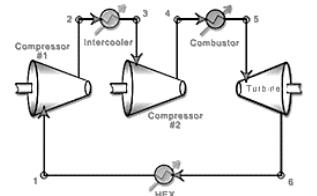
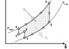
Figure 3: Intercooling on Brayton cycle
For ideal cycle with intercooling
Wc = C p (T 2a -T 1) + (T 2 -T 2b)
Heat supplied
Qs = C p (T 3 -T 2)
Work by turbine: W t =C p (T 3 -T 4)
Thermal efficiency of gas turbine cycle with intercooling:

Key takeaway:
- When the temperature of the air leaving the intercooler is equal to the original atmospheric air temperature, then this is known as known as Complete or Perfect Intercooling.
- When the temperature of the air leaving the intercooling is more than the original atmosphere air temperature, then this is known as incomplete or Imperfect Intercooling.
- Thermal efficiency of gas turbine cycle with intercooling:

Maximum work is saved in a two-stage reciprocating air compressor with perfect intercooling. Work required to be done by a two-stage reciprocating air-compressor with complete intercooling is given by-

If the intake pressure and delivery pressure are constant, then the least value of the intermediate or intercooler pressure may be obtained by differentiating the above equation with respect to intercooler pressure. At this value of intercooler pressure, the work required to drive the compressor is minimum.


Now considering  (a constant)


This is the condition of minimum work required for a two stage reciprocating air-compressor,
Now Substituting  in equation (1)


In, general for compressor having q number of stages,
Condition for minimum work required,

And minimum work required for compression,

Key takeaway:
- Work required to be done by a two-stage reciprocating air-compressor with complete intercooling is given by-

- Minimum power required for compression is given by-

References:
1. Sonntag, R. E, Borgnakke, C. And Van Wylen, G. J., 2003, 6th Edition, Fundamentals of Thermodynamics, John Wiley and Sons.
2. Jones, J. B. And Duggan, R. E., 1996, Engineering Thermodynamics, Prentice-Hall of India
3. Moran, M. J. And Shapiro, H. N., 1999, Fundamentals of Engineering Thermodynamics, John Wiley and Sons.
4. Yunus A. Cengel; Michael A. Boles, Thermodynamics: An Engineering Approach, McGraw- Hill.
5. Nag, P.K, 1995, Engineering Thermodynamics, Tata McGraw-Hill Publishing Co. Ltd.
Unit - 5
Reciprocating Compressors
Principles on which compressors work:
A compressor is a mechanical device that increases the pressure of a gas by reducing its volume. (The fluid here is generally air since liquids are theoretically incompressible).
Classification of compressor:
There are mainly two types of Compressors-
- Reciprocating compressor
- Single stage
- Multi stage
2. Rotary compressor
Reciprocating compressor:
In a reciprocating compressor, a volume of gas is drawn into a cylinder, it is trapped, and compressed by piston and then discharged into the discharge line. The cylinder valves control the flow of gas through the cylinder and these valves act as check valves.
Reciprocating compressors can be Single acting or double acting.
Reciprocating compressor types:
- Single–Stage Reciprocating Compressor:
Compression is done in single stage or by single cylinder only and it is used for generation of low-pressure air.
2. Double–stage Reciprocating Compressor:
It is a compressor that produces highly pressurized air and mostly it is used nowadays in heavy duty mechanical devices.
Different parts of reciprocating compressor:
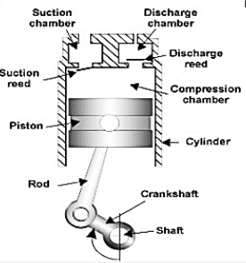
Figure1: Reciprocating compressor
- Suction valve.
- Suction Chamber.
- Piston & Piston Rod.
- Cylinder.
- Discharge valve.
- Discharge Chamber.
Principle of Operation:

Figure 2: Operation of Reciprocating compressor
- Figure 2 shows single-acting piston actions in the cylinder of a reciprocating compressor.
- The piston is driven by a crank shaft via a connecting rod.
- At the top of the cylinder are a suction valve and a discharge valve.
- A reciprocating compressor usually has two, three, four, or six cylinders in it.
- As the piston travels toward the bottom dead center, the volume of the cylinder increases and due to the pressure difference the suction valve is opened.
- The pressure inside the cylinder is slightly less than suction line pressure. So, the volume of the gas starts increasing as the piston moves towards BDC.
- So, the piston continues its motion towards BDC till the area above piston in the cylinder become full of fluid (gas) & then the suction valve gets closed.
- Now when the crankshaft moves further and completes its revolution the piston also moves in opposite direction this time towards TDC.
- Now, again due to the Pressure difference between the delivery line and inside of the cylinder the delivery valves open in the delivery stroke.
- So, at point 3, the piston reaches the top dead center TDC.
- At top dead center, as the piston comes to a complete stop prior to reversing direction, the pressure across the valve is equal.
- So, the discharge valve is closed.
- At point 2, the pressure inside the cylinder has become slightly greater than discharge line pressure.
- This causes the valve opening allowing the gas to flow out of the cylinder.
- The volume continues to decrease toward point 3, maintaining a sufficient pressure difference across the discharge valve to hold it open.
- Now Again, as the piston moves towards BDC, the gas pressure inside the cylinder becomes less than the suction line pressure, so the suction valve opens again.
- The cycle then starts over again.
- The shape of the re-expansion line (Line 3-4) is dependent on the same compression exponent that determines the shape of the compression line.
Key takeaway:
- So, the discharge valve is closed.
- At point 2, the pressure inside the cylinder has become slightly greater than discharge line pressure.
- This causes the valve opening allowing the gas to flow out of the cylinder.
- The volume continues to decrease toward point 3, maintaining a sufficient pressure difference across the discharge valve to hold it open.
- Now Again, as the piston moves towards BDC, the gas pressure inside the cylinder becomes less than the suction line pressure, so the suction valve opens again.
- The cycle then starts over again.
Single Stage Reciprocating Air Compressor
Working Principle:
Here, pressure is increased by means of variation in the volume of cylinder obtained by a moving piston.
Construction:
- Single stage single acting air compressor consists of a piston, which reciprocates inside a cylinder having connecting rod and crank mechanism.
- There are inlet and delivery valves mounted in the head of cylinder.
- The inlet and delivery valves are of pressure differential type i.e.; they operate as a result of pressure difference across the valves.

Working:
Working of single stage reciprocating air compressor is completed in two strokes.
a). Suction Stroke:
- When the piston moves in the downward direction, from (T.D.C.) to (B.D.C), the air compressed in the previous compressions and entrapped in the clearance space begins to expand.
- Due to expansion, the pressure of air inside the cylinder starts to decrease.
- After some travel of piston from T.D.C. Towards B.D.C, the pressure of air inside the cylinder falls below the atmospheric pressure.
- Thus, due to pressure difference, the inlet valve gets opened. Now, the atmospheric air is sucked into the cylinder.
b). Compression Stroke:
- When the piston starts moving from BDC to TDC, the pressure of sucked air inside the cylinder begins to increase.
- When the pressure of air inside the cylinder increases above the atmospheric pressure, the inlet valve gets closed.
- Further movement of piston towards TDC causes compression of air sucked during suction stroke.
- Due to this, pressure of air inside the cylinder goes on increasing.
- As soon as, the pressure reaches up to desired discharge pressure, the delivery valve gets opened and compressed air is delivered into the receiver.
- Now again the piston starts moving from TDC to BDC, and the cycle is repeated again and again.
Two stage reciprocating compressor:

- Fig shows schematic arrangement of two stage reciprocating air compressor with water-cooled intercooler.
- It consists of a low-pressure cylinder & a high pressure cylinder.
- Fresh air is sucked from the atmosphere in low pressure cylinder during suction stroke at intake pressure P1& temperature T1.
- After compression in low pressure cylinder air is delivered to the intercooler at pressure P2& temperature T2.
- In intercooler air is cooled to temperature T3 at constant pressure P2.
- After intercooling air is admitted to high pressure cylinder, where it is compressed to pressure P3& temperature T3.
Key takeaway:
- In a single-stage compression, the pressure ratio is less. But sometimes we require a higher-pressure ratio. So, in order to get a large pressure ratio, we can employ a large pressure in a single cylinder or compress the air in two or more cylinders in series.
- There are some disadvantages of using a single-cylinder for employing a higher-pressure ratio: If we use a single-cylinder then the size of the cylinder will become too large, the final temperature of compressed air increases and the process no longer remains isothermal.
The optimal stage pressure ratio for a multi stage compression is calculated with well-known formula that assigns an equal ratio for all stages based on the hypotheses that all isentropic efficiencies are also equal.
For minimum power consumption in industrial applications, gases should ideally be cooled at the same time they are being compressed, maintaining their initial temperature as constant during the whole process. The increase in power consumption caused by compressing a gas that is progressively getting hotter, with large mass flows and long operating hours can be economically unstable.
It is given by,
r = 
Key Takeaways:
Important formula for optimal stage compression ratio is given as-
r = 
An intercooler is any mechanical device used to cool a fluid, including liquids or gases, between stages of a multi-stage heating process, typically a heat exchanger that removes waste heat in a gas compressor. They are used in many applications, including compressors, air conditioners, refrigerators, and gas turbines.
Effects of intercooling on Brayton cycle:
- Inter cooling means the removal of heat from compressed air between the stages of compression. It is known that the work input in compression is minimum if the compression process is isothermal.
- In order to achieve isothermal process compression is divided in number of stages and air is cooled between the stages with help of intercooler.
- The greater the number of stages of compression with intercooling between each stage, the closer will be the approximation to an isothermal process.
- The intercooler is a heat exchanger in which compressed air is cooled in order to reduce volume and increase density.
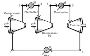
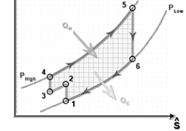
Figure 3: Intercooling on Brayton cycle
For ideal cycle with intercooling
Wc = C p (T 2a -T 1) + (T 2 -T 2b)
Heat supplied
Qs = C p (T 3 -T 2)
Work by turbine: W t =C p (T 3 -T 4)
Thermal efficiency of gas turbine cycle with intercooling:

Key takeaway:
- When the temperature of the air leaving the intercooler is equal to the original atmospheric air temperature, then this is known as known as Complete or Perfect Intercooling.
- When the temperature of the air leaving the intercooling is more than the original atmosphere air temperature, then this is known as incomplete or Imperfect Intercooling.
- Thermal efficiency of gas turbine cycle with intercooling:
