Unit - 3
Additive manufacturing
Additive manufacturing process:
In additive manufacturing process, the object is manufactured by deposition of layers of material. In additive manufacturing, virtually there is no wastage of material.
Rapid Prototyping
Rapid Prototyping Technology is a set of manufacturing processes which allows the direct physical cognizance of 3D computer models.
This technology transfers the 3D computer data offered via a dedicated file format directly to a physical model that too layer by layer with a huge degree of accuracy.
Rapid prototyping is nothing but an additive process. This process combines layers of paper, wax, or plastic to generate a solid object. In contrast to many machining processes which are subtractive processes that remove material from a solid block.
Construction of physical model is done automatically from CAD data in RPT.
Fundamentals of Rapid Prototyping
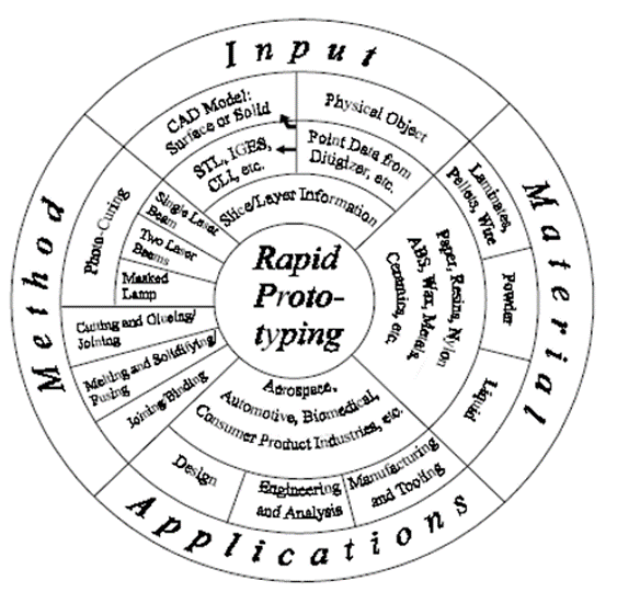
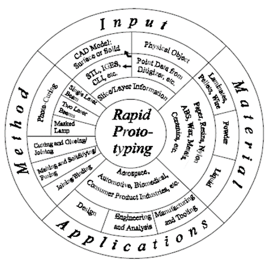
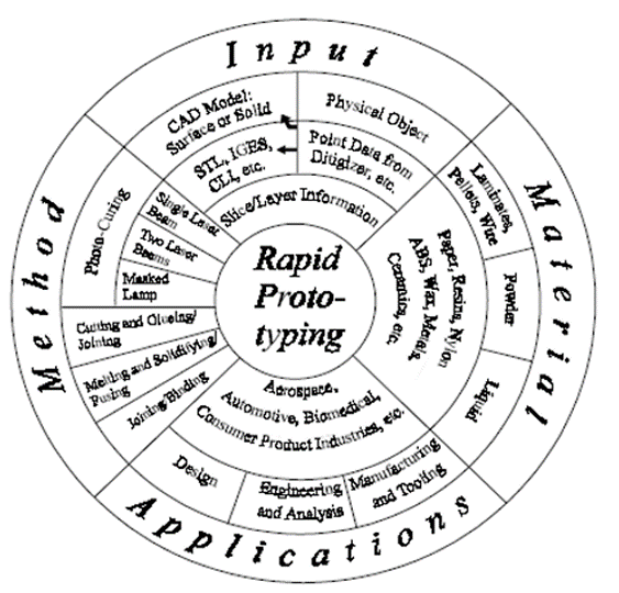
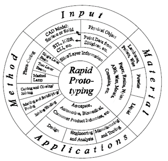
The Rapid Prototyping Wheel depicting the 4 major aspects of RP
- Input
- Input refers to the electronic data needed to describe the physical model with 3D data.
- There are two possible beginning points, which is a computer model or a physical model.
- The computer model created by a CAD system can be either a surface model or a solid model
- On the other hand, 3D data from the physical model is not at all straightforward.
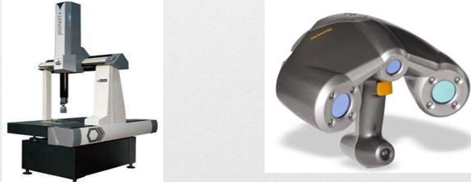
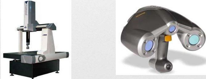
- It requires information acquisition by a approach known as reverse engineering.
b. Method
The method employed by all vendors can be generally categorized into the following types:
• cutting and gluing or joining,
• photo-curing,
• melting and solidifying or fusing and joining or binding.
Photo-curing can be further divided into categories of
• single laser beam,
• masked lamp
• double laser beams and
c. Material
- The initial state of material are either available in solid, liquid or powder state.
- In solid state, material may be available in different forms like pallets, wire or laminates.
d. Application
- Applications can be grouped into:
• Design
• Engineering, Analysis and Planning
• Tooling and Manufacturing
Basic Steps in Rapid Prototyping Process
i) CAD Model Creation:
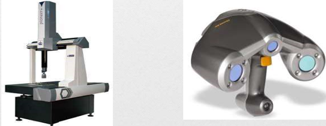
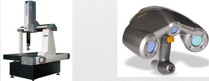
- First, the object that is to be created is modeled with the help of a Computer-Aided Design (CAD) software package or coordinate measuring system or also by laser scanner.
- Solid modelers, for example Pro/ENGINEER, tend to show 3-D objects more perfectly compared to wire-frame modelers like AutoCAD, and hence yield good results.
- This process is same for all of the RP creation techniques.
Ii) Conversion to STL Format:
- The STL format has been adopted, in order to establish consistency, as the standard file format of the rapid prototyping industry and acts as the interface between CAD software and machines.
- The second step in rapid prototyping is to translate the CAD file into STL format. This format gives a 3D surface an assembly of planar triangular facets.
- STL files makes use of a planar elements because they cannot represent curved surfaces perfectly. Maximizing the quantity of triangles improves the approximation. While minimizing these numbers reduces the quality.

Iii) Slice the STL File:
- In the third step, a pre-processing program of rapid prototyping is to prepare the STL file to be generated.
- The pre-processing software cuts the STL model into many number of layers, thickness ranging from 0.01 mm to 0.7 mm, depending on the creation method.
Iv) Layer by Layer Construction:
- The fourth step is the actual construction of the part.
- RP machines create one layer at one time from polymers, paper, or from powdered metal.
- Most machines are not autonomous, requiring some human intervention.
v) Clean and Finish:
- The last step in rapid prototyping is post-processing. This includes removal of the prototype from the machine and detaching the supports if any.
- Some photosensitive materials require to be completely cured prior use
- Prototypes might also need minor cleaning as well as surface treatment.
Classification of Rapid Prototyping
Based on initial form of material used, the rapid prototyping systems are broadly classified into three categories.
a) LIQUID-BASED
- In liquid-based Rapid prototyping systems, the initial form of the material is in liquid state.
- In a process generally called as curing, the liquid material is changed into the solid state.
- The liquid used is organic resin that cures or solidifies under the exposure of light.
- Examples:
a) Stereolithography (SLA)
b) Polyjet Modelling
b) SOLID-BASED
- Except for powder, solid-based rapid prototyping systems have all forms of material in the solid state only.
- The solid form of material can contain the shape in the type of a wire, a roll, laminates and pallets.
- It does not include powder form.
- Examples:
a) Fused Deposition Modelling (FDM)
b) Laminated Object Modelling (LOM)
c) POWDER-BASED
- In a strict sense, powder is by-and-large in the solid state.
- This category is intentionally kept outside the solid-based rapid prototyping systems to mean powder material in grain-like form.
- Examples:
a) Selective Laser Sintering (SLS)
b) 3D- Printing
Rapid-prototyping techniques have made possible much faster product development times, and they are having a major effect on other manufacturing processes. When proper materials are being used, rapid-prototyping machinery can create blanks for investment casting or similar processes. Hence that metallic parts may now be received fastly and economically, even for lot sizes as little as one part.
Such techniques also can be applied to create molds for operations (like injection molding, sand and shell mold casting, and also forging), thereby significantly reducing the lead time between design and manufacture.
Many approaches have been devised for the fast production of tooling (RT) via means of rapid-prototyping processes.
Rapid tooling is the process of manufacturing the tools using the rapid prototyping technique. It is widely used in many areas of industries.
The advantages to rapid tooling include the following:
- There is a much decrease in lead time.
- The high cost of labor and short supply of skilled pattern makers can be overcome.
- Lightweight castings can be produced more easily because hollow designs can be adopted easily
- The integral usage of CAD technologies enables the usage of modular dies with base-mold tooling (match plates) and specially fabricated inserts. This type modular method may further minimize tooling costs.
- Shrinkage because of solidification or thermal contraction may be compensated for automatically via software in order to produce tooling of the right size and hence to produce the desired parts.
The principal shortcoming of RT is the potentially decreased tool or pattern life as compared to the ones acquired from machined tool and die materials, like tool steels or tungsten carbides.
The easiest method of making use of rapid-prototyping operations to different manufacturing processes is in the direct generation of patterns or molds.
Classification of Rapid Tooling:
A] Classification method of tooling:
a. Direct Tooling
Direct Tooling is a process of making the tool, die or mold directly from the CAD data, using rapid prototyping process. For example, in injection molding, the main cavity, cores, runner, ejection system, etc. can be produced directly using rapid prototyping process.
b. Indirect Tooling
Indirect tooling is the process of making the master patterns for making tool, die or mold from CAD data, using rapid prototyping process.
It is not a tool production process but is a pre-production process. SLA, which gives a good accuracy and surface finish, is used as indirect tooling process.
B] Classification based on Material used:
a. Hard Tooling
Hard tooling is the process of making the tool, die or mold from hard materials like steel, using rapid prototyping process.
b. Soft Tooling
Soft tooling is the process of making the tool, die or mold from soft materials like silicon rubber, epoxy resin, low melting point alloys, etc. using rapid prototyping process.
Conventional Tooling vs Rapid Tooling:
RT is distinguished from conventional tooling in that,
- Tooling time is much shorter than for a conventional tool. Time to first articles in RT is less than one-fifth that of conventional tooling.
- Tooling cost is minimum than for a conventional tool. Cost may be less than five percent of conventional tooling cost.
- Tool life is considerably low than for a conventional tool.
- Tolerances are wider than for a traditional tool.
Need of Rapid Tooling (RT)
- Minimize cost
- Increase productivity
- Increase dimensional accuracy
- Decrease tool time
References:
1. Kalpakjian and Schmid, Manufacturing processes for engineering materials (5th Edition)- Pearson India, 2014.
2. Mikell P. Groover, Fundamentals of Modern Manufacturing: Materials, Processes, and Systems.
3. Manufacturing Technology by P.N. Rao., MCGRAW HILL INDIA.
4. Materials and Manufacturing by Paul Degarmo.
5. Manufacturing Processes by Kaushish, PHI.
Unit - 3
Additive manufacturing
Additive manufacturing process:
In additive manufacturing process, the object is manufactured by deposition of layers of material. In additive manufacturing, virtually there is no wastage of material.
Rapid Prototyping
Rapid Prototyping Technology is a set of manufacturing processes which allows the direct physical cognizance of 3D computer models.
This technology transfers the 3D computer data offered via a dedicated file format directly to a physical model that too layer by layer with a huge degree of accuracy.
Rapid prototyping is nothing but an additive process. This process combines layers of paper, wax, or plastic to generate a solid object. In contrast to many machining processes which are subtractive processes that remove material from a solid block.
Construction of physical model is done automatically from CAD data in RPT.
Fundamentals of Rapid Prototyping
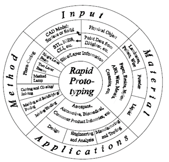
The Rapid Prototyping Wheel depicting the 4 major aspects of RP
- Input
- Input refers to the electronic data needed to describe the physical model with 3D data.
- There are two possible beginning points, which is a computer model or a physical model.
- The computer model created by a CAD system can be either a surface model or a solid model
- On the other hand, 3D data from the physical model is not at all straightforward.
- It requires information acquisition by a approach known as reverse engineering.
b. Method
The method employed by all vendors can be generally categorized into the following types:
• cutting and gluing or joining,
• photo-curing,
• melting and solidifying or fusing and joining or binding.
Photo-curing can be further divided into categories of
• single laser beam,
• masked lamp
• double laser beams and
c. Material
- The initial state of material are either available in solid, liquid or powder state.
- In solid state, material may be available in different forms like pallets, wire or laminates.
d. Application
- Applications can be grouped into:
• Design
• Engineering, Analysis and Planning
• Tooling and Manufacturing
Basic Steps in Rapid Prototyping Process
i) CAD Model Creation:
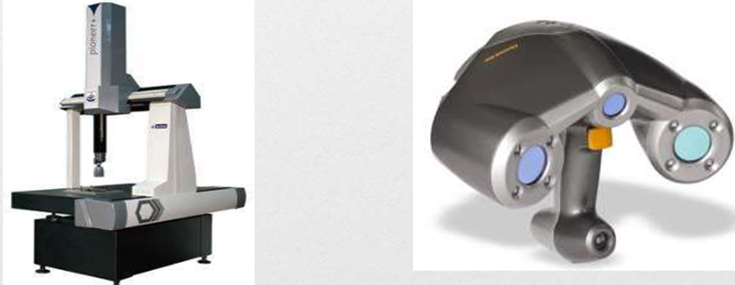
- First, the object that is to be created is modeled with the help of a Computer-Aided Design (CAD) software package or coordinate measuring system or also by laser scanner.
- Solid modelers, for example Pro/ENGINEER, tend to show 3-D objects more perfectly compared to wire-frame modelers like AutoCAD, and hence yield good results.
- This process is same for all of the RP creation techniques.
Ii) Conversion to STL Format:
- The STL format has been adopted, in order to establish consistency, as the standard file format of the rapid prototyping industry and acts as the interface between CAD software and machines.
- The second step in rapid prototyping is to translate the CAD file into STL format. This format gives a 3D surface an assembly of planar triangular facets.
- STL files makes use of a planar elements because they cannot represent curved surfaces perfectly. Maximizing the quantity of triangles improves the approximation. While minimizing these numbers reduces the quality.

Iii) Slice the STL File:
- In the third step, a pre-processing program of rapid prototyping is to prepare the STL file to be generated.
- The pre-processing software cuts the STL model into many number of layers, thickness ranging from 0.01 mm to 0.7 mm, depending on the creation method.
Iv) Layer by Layer Construction:
- The fourth step is the actual construction of the part.
- RP machines create one layer at one time from polymers, paper, or from powdered metal.
- Most machines are not autonomous, requiring some human intervention.
v) Clean and Finish:
- The last step in rapid prototyping is post-processing. This includes removal of the prototype from the machine and detaching the supports if any.
- Some photosensitive materials require to be completely cured prior use
- Prototypes might also need minor cleaning as well as surface treatment.
Classification of Rapid Prototyping
Based on initial form of material used, the rapid prototyping systems are broadly classified into three categories.
a) LIQUID-BASED
- In liquid-based Rapid prototyping systems, the initial form of the material is in liquid state.
- In a process generally called as curing, the liquid material is changed into the solid state.
- The liquid used is organic resin that cures or solidifies under the exposure of light.
- Examples:
a) Stereolithography (SLA)
b) Polyjet Modelling
b) SOLID-BASED
- Except for powder, solid-based rapid prototyping systems have all forms of material in the solid state only.
- The solid form of material can contain the shape in the type of a wire, a roll, laminates and pallets.
- It does not include powder form.
- Examples:
a) Fused Deposition Modelling (FDM)
b) Laminated Object Modelling (LOM)
c) POWDER-BASED
- In a strict sense, powder is by-and-large in the solid state.
- This category is intentionally kept outside the solid-based rapid prototyping systems to mean powder material in grain-like form.
- Examples:
a) Selective Laser Sintering (SLS)
b) 3D- Printing
Rapid-prototyping techniques have made possible much faster product development times, and they are having a major effect on other manufacturing processes. When proper materials are being used, rapid-prototyping machinery can create blanks for investment casting or similar processes. Hence that metallic parts may now be received fastly and economically, even for lot sizes as little as one part.
Such techniques also can be applied to create molds for operations (like injection molding, sand and shell mold casting, and also forging), thereby significantly reducing the lead time between design and manufacture.
Many approaches have been devised for the fast production of tooling (RT) via means of rapid-prototyping processes.
Rapid tooling is the process of manufacturing the tools using the rapid prototyping technique. It is widely used in many areas of industries.
The advantages to rapid tooling include the following:
- There is a much decrease in lead time.
- The high cost of labor and short supply of skilled pattern makers can be overcome.
- Lightweight castings can be produced more easily because hollow designs can be adopted easily
- The integral usage of CAD technologies enables the usage of modular dies with base-mold tooling (match plates) and specially fabricated inserts. This type modular method may further minimize tooling costs.
- Shrinkage because of solidification or thermal contraction may be compensated for automatically via software in order to produce tooling of the right size and hence to produce the desired parts.
The principal shortcoming of RT is the potentially decreased tool or pattern life as compared to the ones acquired from machined tool and die materials, like tool steels or tungsten carbides.
The easiest method of making use of rapid-prototyping operations to different manufacturing processes is in the direct generation of patterns or molds.
Classification of Rapid Tooling:
A] Classification method of tooling:
a. Direct Tooling
Direct Tooling is a process of making the tool, die or mold directly from the CAD data, using rapid prototyping process. For example, in injection molding, the main cavity, cores, runner, ejection system, etc. can be produced directly using rapid prototyping process.
b. Indirect Tooling
Indirect tooling is the process of making the master patterns for making tool, die or mold from CAD data, using rapid prototyping process.
It is not a tool production process but is a pre-production process. SLA, which gives a good accuracy and surface finish, is used as indirect tooling process.
B] Classification based on Material used:
a. Hard Tooling
Hard tooling is the process of making the tool, die or mold from hard materials like steel, using rapid prototyping process.
b. Soft Tooling
Soft tooling is the process of making the tool, die or mold from soft materials like silicon rubber, epoxy resin, low melting point alloys, etc. using rapid prototyping process.
Conventional Tooling vs Rapid Tooling:
RT is distinguished from conventional tooling in that,
- Tooling time is much shorter than for a conventional tool. Time to first articles in RT is less than one-fifth that of conventional tooling.
- Tooling cost is minimum than for a conventional tool. Cost may be less than five percent of conventional tooling cost.
- Tool life is considerably low than for a conventional tool.
- Tolerances are wider than for a traditional tool.
Need of Rapid Tooling (RT)
- Minimize cost
- Increase productivity
- Increase dimensional accuracy
- Decrease tool time
References:
1. Kalpakjian and Schmid, Manufacturing processes for engineering materials (5th Edition)- Pearson India, 2014.
2. Mikell P. Groover, Fundamentals of Modern Manufacturing: Materials, Processes, and Systems.
3. Manufacturing Technology by P.N. Rao., MCGRAW HILL INDIA.
4. Materials and Manufacturing by Paul Degarmo.
5. Manufacturing Processes by Kaushish, PHI.
Unit - 3
Additive manufacturing
Additive manufacturing process:
In additive manufacturing process, the object is manufactured by deposition of layers of material. In additive manufacturing, virtually there is no wastage of material.
Rapid Prototyping
Rapid Prototyping Technology is a set of manufacturing processes which allows the direct physical cognizance of 3D computer models.
This technology transfers the 3D computer data offered via a dedicated file format directly to a physical model that too layer by layer with a huge degree of accuracy.
Rapid prototyping is nothing but an additive process. This process combines layers of paper, wax, or plastic to generate a solid object. In contrast to many machining processes which are subtractive processes that remove material from a solid block.
Construction of physical model is done automatically from CAD data in RPT.
Fundamentals of Rapid Prototyping
The Rapid Prototyping Wheel depicting the 4 major aspects of RP
- Input
- Input refers to the electronic data needed to describe the physical model with 3D data.
- There are two possible beginning points, which is a computer model or a physical model.
- The computer model created by a CAD system can be either a surface model or a solid model
- On the other hand, 3D data from the physical model is not at all straightforward.
- It requires information acquisition by a approach known as reverse engineering.
b. Method
The method employed by all vendors can be generally categorized into the following types:
• cutting and gluing or joining,
• photo-curing,
• melting and solidifying or fusing and joining or binding.
Photo-curing can be further divided into categories of
• single laser beam,
• masked lamp
• double laser beams and
c. Material
- The initial state of material are either available in solid, liquid or powder state.
- In solid state, material may be available in different forms like pallets, wire or laminates.
d. Application
- Applications can be grouped into:
• Design
• Engineering, Analysis and Planning
• Tooling and Manufacturing
Basic Steps in Rapid Prototyping Process
i) CAD Model Creation:
- First, the object that is to be created is modeled with the help of a Computer-Aided Design (CAD) software package or coordinate measuring system or also by laser scanner.
- Solid modelers, for example Pro/ENGINEER, tend to show 3-D objects more perfectly compared to wire-frame modelers like AutoCAD, and hence yield good results.
- This process is same for all of the RP creation techniques.
Ii) Conversion to STL Format:
- The STL format has been adopted, in order to establish consistency, as the standard file format of the rapid prototyping industry and acts as the interface between CAD software and machines.
- The second step in rapid prototyping is to translate the CAD file into STL format. This format gives a 3D surface an assembly of planar triangular facets.
- STL files makes use of a planar elements because they cannot represent curved surfaces perfectly. Maximizing the quantity of triangles improves the approximation. While minimizing these numbers reduces the quality.

Iii) Slice the STL File:
- In the third step, a pre-processing program of rapid prototyping is to prepare the STL file to be generated.
- The pre-processing software cuts the STL model into many number of layers, thickness ranging from 0.01 mm to 0.7 mm, depending on the creation method.
Iv) Layer by Layer Construction:
- The fourth step is the actual construction of the part.
- RP machines create one layer at one time from polymers, paper, or from powdered metal.
- Most machines are not autonomous, requiring some human intervention.
v) Clean and Finish:
- The last step in rapid prototyping is post-processing. This includes removal of the prototype from the machine and detaching the supports if any.
- Some photosensitive materials require to be completely cured prior use
- Prototypes might also need minor cleaning as well as surface treatment.
Classification of Rapid Prototyping
Based on initial form of material used, the rapid prototyping systems are broadly classified into three categories.
a) LIQUID-BASED
- In liquid-based Rapid prototyping systems, the initial form of the material is in liquid state.
- In a process generally called as curing, the liquid material is changed into the solid state.
- The liquid used is organic resin that cures or solidifies under the exposure of light.
- Examples:
a) Stereolithography (SLA)
b) Polyjet Modelling
b) SOLID-BASED
- Except for powder, solid-based rapid prototyping systems have all forms of material in the solid state only.
- The solid form of material can contain the shape in the type of a wire, a roll, laminates and pallets.
- It does not include powder form.
- Examples:
a) Fused Deposition Modelling (FDM)
b) Laminated Object Modelling (LOM)
c) POWDER-BASED
- In a strict sense, powder is by-and-large in the solid state.
- This category is intentionally kept outside the solid-based rapid prototyping systems to mean powder material in grain-like form.
- Examples:
a) Selective Laser Sintering (SLS)
b) 3D- Printing
Rapid-prototyping techniques have made possible much faster product development times, and they are having a major effect on other manufacturing processes. When proper materials are being used, rapid-prototyping machinery can create blanks for investment casting or similar processes. Hence that metallic parts may now be received fastly and economically, even for lot sizes as little as one part.
Such techniques also can be applied to create molds for operations (like injection molding, sand and shell mold casting, and also forging), thereby significantly reducing the lead time between design and manufacture.
Many approaches have been devised for the fast production of tooling (RT) via means of rapid-prototyping processes.
Rapid tooling is the process of manufacturing the tools using the rapid prototyping technique. It is widely used in many areas of industries.
The advantages to rapid tooling include the following:
- There is a much decrease in lead time.
- The high cost of labor and short supply of skilled pattern makers can be overcome.
- Lightweight castings can be produced more easily because hollow designs can be adopted easily
- The integral usage of CAD technologies enables the usage of modular dies with base-mold tooling (match plates) and specially fabricated inserts. This type modular method may further minimize tooling costs.
- Shrinkage because of solidification or thermal contraction may be compensated for automatically via software in order to produce tooling of the right size and hence to produce the desired parts.
The principal shortcoming of RT is the potentially decreased tool or pattern life as compared to the ones acquired from machined tool and die materials, like tool steels or tungsten carbides.
The easiest method of making use of rapid-prototyping operations to different manufacturing processes is in the direct generation of patterns or molds.
Classification of Rapid Tooling:
A] Classification method of tooling:
a. Direct Tooling
Direct Tooling is a process of making the tool, die or mold directly from the CAD data, using rapid prototyping process. For example, in injection molding, the main cavity, cores, runner, ejection system, etc. can be produced directly using rapid prototyping process.
b. Indirect Tooling
Indirect tooling is the process of making the master patterns for making tool, die or mold from CAD data, using rapid prototyping process.
It is not a tool production process but is a pre-production process. SLA, which gives a good accuracy and surface finish, is used as indirect tooling process.
B] Classification based on Material used:
a. Hard Tooling
Hard tooling is the process of making the tool, die or mold from hard materials like steel, using rapid prototyping process.
b. Soft Tooling
Soft tooling is the process of making the tool, die or mold from soft materials like silicon rubber, epoxy resin, low melting point alloys, etc. using rapid prototyping process.
Conventional Tooling vs Rapid Tooling:
RT is distinguished from conventional tooling in that,
- Tooling time is much shorter than for a conventional tool. Time to first articles in RT is less than one-fifth that of conventional tooling.
- Tooling cost is minimum than for a conventional tool. Cost may be less than five percent of conventional tooling cost.
- Tool life is considerably low than for a conventional tool.
- Tolerances are wider than for a traditional tool.
Need of Rapid Tooling (RT)
- Minimize cost
- Increase productivity
- Increase dimensional accuracy
- Decrease tool time
References:
1. Kalpakjian and Schmid, Manufacturing processes for engineering materials (5th Edition)- Pearson India, 2014.
2. Mikell P. Groover, Fundamentals of Modern Manufacturing: Materials, Processes, and Systems.
3. Manufacturing Technology by P.N. Rao., MCGRAW HILL INDIA.
4. Materials and Manufacturing by Paul Degarmo.
5. Manufacturing Processes by Kaushish, PHI.
Unit - 3
Additive manufacturing
Additive manufacturing process:
In additive manufacturing process, the object is manufactured by deposition of layers of material. In additive manufacturing, virtually there is no wastage of material.
Rapid Prototyping
Rapid Prototyping Technology is a set of manufacturing processes which allows the direct physical cognizance of 3D computer models.
This technology transfers the 3D computer data offered via a dedicated file format directly to a physical model that too layer by layer with a huge degree of accuracy.
Rapid prototyping is nothing but an additive process. This process combines layers of paper, wax, or plastic to generate a solid object. In contrast to many machining processes which are subtractive processes that remove material from a solid block.
Construction of physical model is done automatically from CAD data in RPT.
Fundamentals of Rapid Prototyping
The Rapid Prototyping Wheel depicting the 4 major aspects of RP
- Input
- Input refers to the electronic data needed to describe the physical model with 3D data.
- There are two possible beginning points, which is a computer model or a physical model.
- The computer model created by a CAD system can be either a surface model or a solid model
- On the other hand, 3D data from the physical model is not at all straightforward.
- It requires information acquisition by a approach known as reverse engineering.
b. Method
The method employed by all vendors can be generally categorized into the following types:
• cutting and gluing or joining,
• photo-curing,
• melting and solidifying or fusing and joining or binding.
Photo-curing can be further divided into categories of
• single laser beam,
• masked lamp
• double laser beams and
c. Material
- The initial state of material are either available in solid, liquid or powder state.
- In solid state, material may be available in different forms like pallets, wire or laminates.
d. Application
- Applications can be grouped into:
• Design
• Engineering, Analysis and Planning
• Tooling and Manufacturing
Basic Steps in Rapid Prototyping Process
i) CAD Model Creation:
- First, the object that is to be created is modeled with the help of a Computer-Aided Design (CAD) software package or coordinate measuring system or also by laser scanner.
- Solid modelers, for example Pro/ENGINEER, tend to show 3-D objects more perfectly compared to wire-frame modelers like AutoCAD, and hence yield good results.
- This process is same for all of the RP creation techniques.
Ii) Conversion to STL Format:
- The STL format has been adopted, in order to establish consistency, as the standard file format of the rapid prototyping industry and acts as the interface between CAD software and machines.
- The second step in rapid prototyping is to translate the CAD file into STL format. This format gives a 3D surface an assembly of planar triangular facets.
- STL files makes use of a planar elements because they cannot represent curved surfaces perfectly. Maximizing the quantity of triangles improves the approximation. While minimizing these numbers reduces the quality.

Iii) Slice the STL File:
- In the third step, a pre-processing program of rapid prototyping is to prepare the STL file to be generated.
- The pre-processing software cuts the STL model into many number of layers, thickness ranging from 0.01 mm to 0.7 mm, depending on the creation method.
Iv) Layer by Layer Construction:
- The fourth step is the actual construction of the part.
- RP machines create one layer at one time from polymers, paper, or from powdered metal.
- Most machines are not autonomous, requiring some human intervention.
v) Clean and Finish:
- The last step in rapid prototyping is post-processing. This includes removal of the prototype from the machine and detaching the supports if any.
- Some photosensitive materials require to be completely cured prior use
- Prototypes might also need minor cleaning as well as surface treatment.
Classification of Rapid Prototyping
Based on initial form of material used, the rapid prototyping systems are broadly classified into three categories.
a) LIQUID-BASED
- In liquid-based Rapid prototyping systems, the initial form of the material is in liquid state.
- In a process generally called as curing, the liquid material is changed into the solid state.
- The liquid used is organic resin that cures or solidifies under the exposure of light.
- Examples:
a) Stereolithography (SLA)
b) Polyjet Modelling
b) SOLID-BASED
- Except for powder, solid-based rapid prototyping systems have all forms of material in the solid state only.
- The solid form of material can contain the shape in the type of a wire, a roll, laminates and pallets.
- It does not include powder form.
- Examples:
a) Fused Deposition Modelling (FDM)
b) Laminated Object Modelling (LOM)
c) POWDER-BASED
- In a strict sense, powder is by-and-large in the solid state.
- This category is intentionally kept outside the solid-based rapid prototyping systems to mean powder material in grain-like form.
- Examples:
a) Selective Laser Sintering (SLS)
b) 3D- Printing
Rapid-prototyping techniques have made possible much faster product development times, and they are having a major effect on other manufacturing processes. When proper materials are being used, rapid-prototyping machinery can create blanks for investment casting or similar processes. Hence that metallic parts may now be received fastly and economically, even for lot sizes as little as one part.
Such techniques also can be applied to create molds for operations (like injection molding, sand and shell mold casting, and also forging), thereby significantly reducing the lead time between design and manufacture.
Many approaches have been devised for the fast production of tooling (RT) via means of rapid-prototyping processes.
Rapid tooling is the process of manufacturing the tools using the rapid prototyping technique. It is widely used in many areas of industries.
The advantages to rapid tooling include the following:
- There is a much decrease in lead time.
- The high cost of labor and short supply of skilled pattern makers can be overcome.
- Lightweight castings can be produced more easily because hollow designs can be adopted easily
- The integral usage of CAD technologies enables the usage of modular dies with base-mold tooling (match plates) and specially fabricated inserts. This type modular method may further minimize tooling costs.
- Shrinkage because of solidification or thermal contraction may be compensated for automatically via software in order to produce tooling of the right size and hence to produce the desired parts.
The principal shortcoming of RT is the potentially decreased tool or pattern life as compared to the ones acquired from machined tool and die materials, like tool steels or tungsten carbides.
The easiest method of making use of rapid-prototyping operations to different manufacturing processes is in the direct generation of patterns or molds.
Classification of Rapid Tooling:
A] Classification method of tooling:
a. Direct Tooling
Direct Tooling is a process of making the tool, die or mold directly from the CAD data, using rapid prototyping process. For example, in injection molding, the main cavity, cores, runner, ejection system, etc. can be produced directly using rapid prototyping process.
b. Indirect Tooling
Indirect tooling is the process of making the master patterns for making tool, die or mold from CAD data, using rapid prototyping process.
It is not a tool production process but is a pre-production process. SLA, which gives a good accuracy and surface finish, is used as indirect tooling process.
B] Classification based on Material used:
a. Hard Tooling
Hard tooling is the process of making the tool, die or mold from hard materials like steel, using rapid prototyping process.
b. Soft Tooling
Soft tooling is the process of making the tool, die or mold from soft materials like silicon rubber, epoxy resin, low melting point alloys, etc. using rapid prototyping process.
Conventional Tooling vs Rapid Tooling:
RT is distinguished from conventional tooling in that,
- Tooling time is much shorter than for a conventional tool. Time to first articles in RT is less than one-fifth that of conventional tooling.
- Tooling cost is minimum than for a conventional tool. Cost may be less than five percent of conventional tooling cost.
- Tool life is considerably low than for a conventional tool.
- Tolerances are wider than for a traditional tool.
Need of Rapid Tooling (RT)
- Minimize cost
- Increase productivity
- Increase dimensional accuracy
- Decrease tool time
References:
1. Kalpakjian and Schmid, Manufacturing processes for engineering materials (5th Edition)- Pearson India, 2014.
2. Mikell P. Groover, Fundamentals of Modern Manufacturing: Materials, Processes, and Systems.
3. Manufacturing Technology by P.N. Rao., MCGRAW HILL INDIA.
4. Materials and Manufacturing by Paul Degarmo.
5. Manufacturing Processes by Kaushish, PHI.
Unit - 3
Additive manufacturing
Additive manufacturing process:
In additive manufacturing process, the object is manufactured by deposition of layers of material. In additive manufacturing, virtually there is no wastage of material.
Rapid Prototyping
Rapid Prototyping Technology is a set of manufacturing processes which allows the direct physical cognizance of 3D computer models.
This technology transfers the 3D computer data offered via a dedicated file format directly to a physical model that too layer by layer with a huge degree of accuracy.
Rapid prototyping is nothing but an additive process. This process combines layers of paper, wax, or plastic to generate a solid object. In contrast to many machining processes which are subtractive processes that remove material from a solid block.
Construction of physical model is done automatically from CAD data in RPT.
Fundamentals of Rapid Prototyping
The Rapid Prototyping Wheel depicting the 4 major aspects of RP
- Input
- Input refers to the electronic data needed to describe the physical model with 3D data.
- There are two possible beginning points, which is a computer model or a physical model.
- The computer model created by a CAD system can be either a surface model or a solid model
- On the other hand, 3D data from the physical model is not at all straightforward.
- It requires information acquisition by a approach known as reverse engineering.
b. Method
The method employed by all vendors can be generally categorized into the following types:
• cutting and gluing or joining,
• photo-curing,
• melting and solidifying or fusing and joining or binding.
Photo-curing can be further divided into categories of
• single laser beam,
• masked lamp
• double laser beams and
c. Material
- The initial state of material are either available in solid, liquid or powder state.
- In solid state, material may be available in different forms like pallets, wire or laminates.
d. Application
- Applications can be grouped into:
• Design
• Engineering, Analysis and Planning
• Tooling and Manufacturing
Basic Steps in Rapid Prototyping Process
i) CAD Model Creation:
- First, the object that is to be created is modeled with the help of a Computer-Aided Design (CAD) software package or coordinate measuring system or also by laser scanner.
- Solid modelers, for example Pro/ENGINEER, tend to show 3-D objects more perfectly compared to wire-frame modelers like AutoCAD, and hence yield good results.
- This process is same for all of the RP creation techniques.
Ii) Conversion to STL Format:
- The STL format has been adopted, in order to establish consistency, as the standard file format of the rapid prototyping industry and acts as the interface between CAD software and machines.
- The second step in rapid prototyping is to translate the CAD file into STL format. This format gives a 3D surface an assembly of planar triangular facets.
- STL files makes use of a planar elements because they cannot represent curved surfaces perfectly. Maximizing the quantity of triangles improves the approximation. While minimizing these numbers reduces the quality.

Iii) Slice the STL File:
- In the third step, a pre-processing program of rapid prototyping is to prepare the STL file to be generated.
- The pre-processing software cuts the STL model into many number of layers, thickness ranging from 0.01 mm to 0.7 mm, depending on the creation method.
Iv) Layer by Layer Construction:
- The fourth step is the actual construction of the part.
- RP machines create one layer at one time from polymers, paper, or from powdered metal.
- Most machines are not autonomous, requiring some human intervention.
v) Clean and Finish:
- The last step in rapid prototyping is post-processing. This includes removal of the prototype from the machine and detaching the supports if any.
- Some photosensitive materials require to be completely cured prior use
- Prototypes might also need minor cleaning as well as surface treatment.
Classification of Rapid Prototyping
Based on initial form of material used, the rapid prototyping systems are broadly classified into three categories.
a) LIQUID-BASED
- In liquid-based Rapid prototyping systems, the initial form of the material is in liquid state.
- In a process generally called as curing, the liquid material is changed into the solid state.
- The liquid used is organic resin that cures or solidifies under the exposure of light.
- Examples:
a) Stereolithography (SLA)
b) Polyjet Modelling
b) SOLID-BASED
- Except for powder, solid-based rapid prototyping systems have all forms of material in the solid state only.
- The solid form of material can contain the shape in the type of a wire, a roll, laminates and pallets.
- It does not include powder form.
- Examples:
a) Fused Deposition Modelling (FDM)
b) Laminated Object Modelling (LOM)
c) POWDER-BASED
- In a strict sense, powder is by-and-large in the solid state.
- This category is intentionally kept outside the solid-based rapid prototyping systems to mean powder material in grain-like form.
- Examples:
a) Selective Laser Sintering (SLS)
b) 3D- Printing
Rapid-prototyping techniques have made possible much faster product development times, and they are having a major effect on other manufacturing processes. When proper materials are being used, rapid-prototyping machinery can create blanks for investment casting or similar processes. Hence that metallic parts may now be received fastly and economically, even for lot sizes as little as one part.
Such techniques also can be applied to create molds for operations (like injection molding, sand and shell mold casting, and also forging), thereby significantly reducing the lead time between design and manufacture.
Many approaches have been devised for the fast production of tooling (RT) via means of rapid-prototyping processes.
Rapid tooling is the process of manufacturing the tools using the rapid prototyping technique. It is widely used in many areas of industries.
The advantages to rapid tooling include the following:
- There is a much decrease in lead time.
- The high cost of labor and short supply of skilled pattern makers can be overcome.
- Lightweight castings can be produced more easily because hollow designs can be adopted easily
- The integral usage of CAD technologies enables the usage of modular dies with base-mold tooling (match plates) and specially fabricated inserts. This type modular method may further minimize tooling costs.
- Shrinkage because of solidification or thermal contraction may be compensated for automatically via software in order to produce tooling of the right size and hence to produce the desired parts.
The principal shortcoming of RT is the potentially decreased tool or pattern life as compared to the ones acquired from machined tool and die materials, like tool steels or tungsten carbides.
The easiest method of making use of rapid-prototyping operations to different manufacturing processes is in the direct generation of patterns or molds.
Classification of Rapid Tooling:
A] Classification method of tooling:
a. Direct Tooling
Direct Tooling is a process of making the tool, die or mold directly from the CAD data, using rapid prototyping process. For example, in injection molding, the main cavity, cores, runner, ejection system, etc. can be produced directly using rapid prototyping process.
b. Indirect Tooling
Indirect tooling is the process of making the master patterns for making tool, die or mold from CAD data, using rapid prototyping process.
It is not a tool production process but is a pre-production process. SLA, which gives a good accuracy and surface finish, is used as indirect tooling process.
B] Classification based on Material used:
a. Hard Tooling
Hard tooling is the process of making the tool, die or mold from hard materials like steel, using rapid prototyping process.
b. Soft Tooling
Soft tooling is the process of making the tool, die or mold from soft materials like silicon rubber, epoxy resin, low melting point alloys, etc. using rapid prototyping process.
Conventional Tooling vs Rapid Tooling:
RT is distinguished from conventional tooling in that,
- Tooling time is much shorter than for a conventional tool. Time to first articles in RT is less than one-fifth that of conventional tooling.
- Tooling cost is minimum than for a conventional tool. Cost may be less than five percent of conventional tooling cost.
- Tool life is considerably low than for a conventional tool.
- Tolerances are wider than for a traditional tool.
Need of Rapid Tooling (RT)
- Minimize cost
- Increase productivity
- Increase dimensional accuracy
- Decrease tool time
References:
1. Kalpakjian and Schmid, Manufacturing processes for engineering materials (5th Edition)- Pearson India, 2014.
2. Mikell P. Groover, Fundamentals of Modern Manufacturing: Materials, Processes, and Systems.
3. Manufacturing Technology by P.N. Rao., MCGRAW HILL INDIA.
4. Materials and Manufacturing by Paul Degarmo.
5. Manufacturing Processes by Kaushish, PHI.