Unit - 5
Unconventional Machining Processes
- Abrasive jet machining (AJM) is one of the advanced machining processes (mechanical energy based) where a high velocity jet of abrasives is utilized to remove material from work surface by impact erosion. The abrasive jet is obtained by accelerating fine abrasive particles in highly pressurized gas (carrier gas). A nozzle is used to convert this pressure energy into kinetic energy and also to direct the jet towards work surface at a particular angle (impingement angle). Upon impact, hard abrasive particles gradually remove material by erosion and sometime assisted by brittle fracture.
- AJM differs from age old sand blasting technique by the achievable level of accuracy and precision. AJM utilizes various abrasives including alumina, silicon carbide, glass beads, sodium bicarbonate, etc.; whereas sand blasting predominantly utilizes only silica sand (SiO2). Although purposes of both the processes are quite identical, cutting parameters are often controlled precisely in AJM and thus it can provide better accuracy and precision.
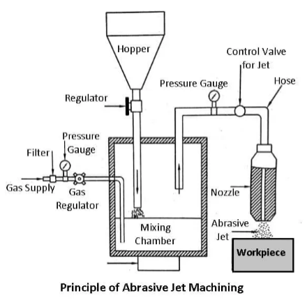
Working Principle of Abrasive Jet Machining
- The fundamental principle of Abrasive jet machining involves the use of a high-speed stream of abrasive particles carried by a high-pressure gas or air on the work surface through a nozzle.
- The metal is removed because of erosion caused by the abrasive particles impacting the work surface at high speed. With repeated impacts, small bits of material get loosened and a fresh surface is exposed to the jet.
- This process is mainly employed for such machining works which are otherwise difficult, such as thin sections of hard metals and alloys, cutting of material which is sensitive of heat damage, producing intricate holes, deburring, etching, polishing etc.
Parts of Abrasive Jet machine
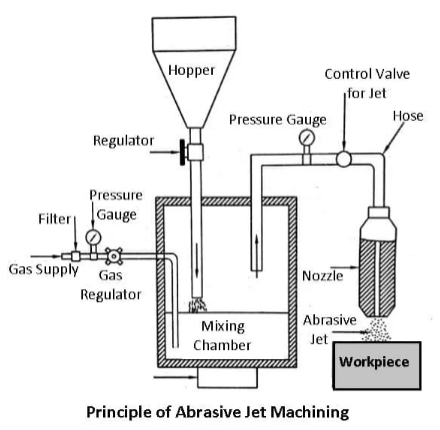
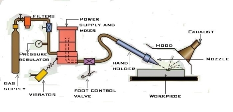
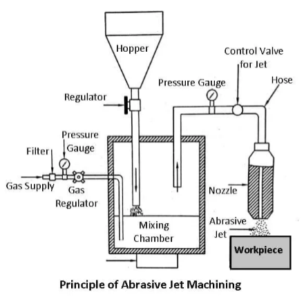
The figure shows a schematic diagram of the abrasive jet machine.
Gas Supply
The filtered gas, supplied under a pressure of 2 to 8 kgf/cm to the mixing chamber containing the abrasive powder and vibrating at 50 Hz entrains the abrasive particles and is then passed into a connecting hose. This abrasive and gas mixture emerges from a small nozzle mounted on a fixture at a high velocity ranging from 150 to 300 m/min.
Abrasive
Abrasive powder feed rate is controlled by the amplitude of vibration of the mixing chamber. The gas flow and pressure is controlled by a pressure regulator. To control the size and shape of the cut either the workpiece or the nozzle is moved by cams, pantographs or other suitable mechanisms.
The abrasives generally used are silicon carbide, aluminium oxide, glass powder or specially prepared sodium bicarbonate. The common particle sizes vary from 10 microns to 50 microns. Smaller sizes are used for good surface finish and precision work. While larger sizes are used for rapid removal rate.
In addition to the above abrasives, dolomite (calcium magnesium carbonate) of 200 grit size is found suitable for light cleaning and etching. Glass beads of diameter 0.30 to 0.60 mm are used for light polishing and deburring.
Nozzle
Nozzles have a great degree of abrasion wear, they’re made of hard materials such as tungsten carbide or synthetic sapphire to reduce the wear rate. Nozzles made of tungsten carbide have an average life of 8 to 12 hours. While nozzles of sapphire last for about 300 hours of operation when used with 27-micron abrasive powder. The gases used are nitrogen, carbon dioxide or clean air.
Workpiece
The metal removal rate depends upon the diameter of the nozzle, the composition of the abrasive gas mixture, the hardness of abrasive particles and that of work material, particle size, the velocity of jet and distance of the workpiece from the jet. A typical material removal rate for abrasive jet machining is 16 mm/min in cutting glass.
Working
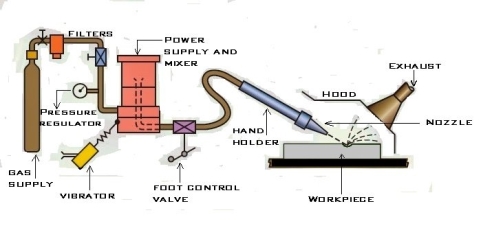
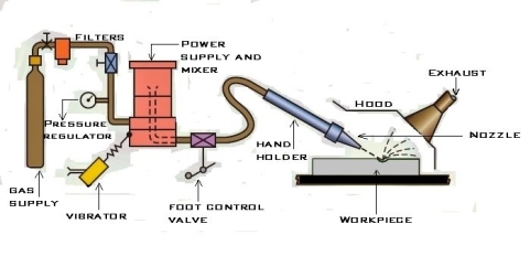
- A typical set-up for abrasive jet machining is shown in the figure. The abrasive particles are held in a suitable holding device, like a tank and fed into the mixing chamber. A regulator is incorporated in the line to control the flow of abrasive particles compressed air or high-pressure gas is supplied to the mixing chamber through a pipeline.
- This pipeline carries a pressure gauge and a regulator to control the gas flow and its pressure. The mixing chamber, carrying the abrasive particles is vibrated and the amplitude of these vibrations controls the flow of abrasive particles.
- These particles mic in the gas stream, travel further through a hose and finally pass through the nozzle at a considerably high speed. This outgoing high-speed stream of the mixture of gas and abrasive particles is known as abrasive jet.
Accuracy
With close control of the various parameters, dimensional tolerance of +0.05 mm are often obtained. On normal production work, the accuracy of +0.1 mm is easily held.
Design consideration for AJM
Material removal is done with cutting speeds between 25 – 125 mm/min. |
Dimensional tolerances are in the range of ± 2 to ± 5 µm. |
Process parameters and their influence on AJM
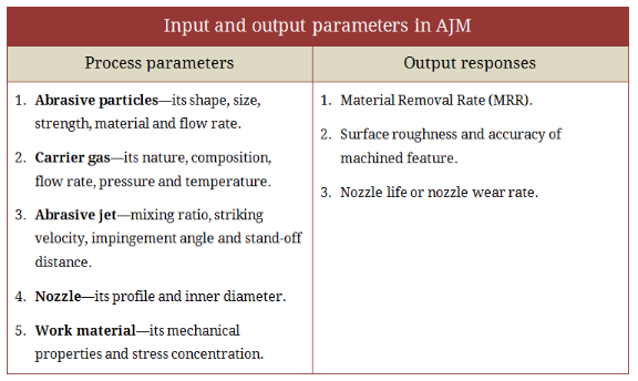
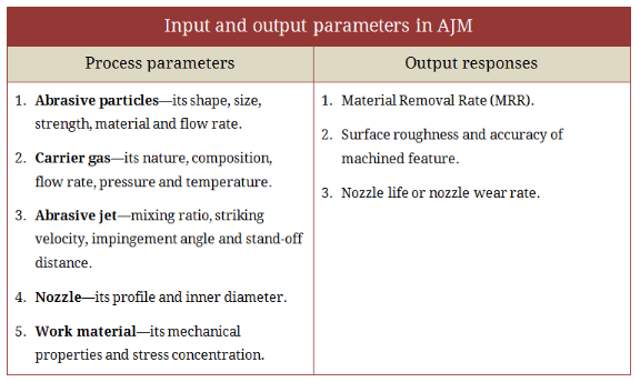
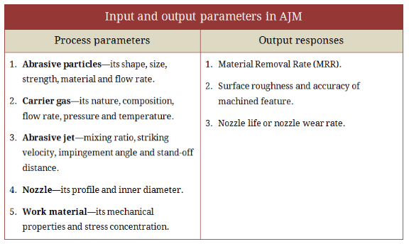
- There are many factors that can influence abrasive jet machining performance. Important process parameters include (i) abrasive particles—its shape, size, strength, material and flow rate; (ii) carrier gas—its nature, composition, flow rate, pressure and temperature; (iii) abrasive jet—mixing ratio, striking velocity, impingement angle and stand-off distance; (iv) nozzle—its profile and inner diameter; and (v) work material—its mechanical properties and stress concentration.
- AJM performance is usually assessed by analyzing three output responses, namely
(i) material removal rate (MRR),
(ii) surface roughness and accuracy of machined feature, and
(iii) nozzle life or nozzle wear rate. Effects of process parameters on AJM performance are discussed below.
Effects of abrasives on AJM performance
- As discussed earlier, shape, size, strength, material and flow rate of abrasive can influence machining performance. Irregular shape abrasives having sharp edges tend to produce higher MRR as compared to spherical grits. Smaller size grits produce highly finished surface but reduce material removal rate (MRR) and thus productivity descends. Larger grits can again create trouble while mixing and flowing through the pipeline. However, variation in size in the entire volume should be low otherwise estimation or assessment will not be accurate.
- Abrasive materials have varying strength or hardness. The harder is the abrasive with respect to work surface hardness, the larger will be the volume removal rate. It is usually the relative hardness between abrasives and workpiece that determines machining capability and productivity.
Effects of carrier gas on AJM performance
- Carrier gas pressure and its flow rate are two paramount factors that determine performance and machining capability. Higher gas pressure reduces jet spreading and thus helps in cutting deeper slots accurately. However, various accessories including pipeline must be capable enough to handle such high pressure without failure. Moreover, increased gas flow rate gives the provision for utilizing higher abrasive flow rate, which can improve productivity.
Effects of mixing ratio on AJM performance
- Mixing ratio (M) is the ratio between mass flow rate of abrasive particles and mass flow rate of carrier gas. It usually determines concentration of abrasives in the jet. Mixing ratio are often increased by increasing abrasive percentage and in such case an increasing trend in MRR are often noticed because larger number of abrasives participates in micro-cutting action per unit time. However, excessive concentration of abrasive in the jet can significantly reduce MRR because of lower jet velocity (as gas pressure is constant) and unavoidable collision (thus loss of kinetic energy).
- MRR are often enhanced by proportionally increasing both the abrasive flow rate and gas flow rate at same rate in order that mixing ratio remains constant. In such case, higher pressure of the carrier gas has to be utilized. This necessitates thicker and stronger pipelines and other accessories to smoothly handle such high pressure without leakage and rupture. Indefinite increase in MRR is not practically feasible because of limited capability of equipment and accessories.
Effect of stand-off distance on AJM performance
- Distance from the work surface to the tip of nozzle in abrasive jet machining set-up is known as Stand-Off Distance, abbreviated as SOD. Higher SOD causes spreading of jet and thus its cross-sectional area increases with the sacrifice of jet velocity. As a consequent, machining deeper slots or hole becomes difficult; instead a wider area is cut. Alternatively smaller SOD can cut a deeper but narrow slot or hole. It also enhances MRR. Thus an optimum value of stand-off distance is required to set for obtaining satisfactory performance in abrasive jet machining.
Effect of impingement angle on AJM performance
- Impingement angle (θ), also known as spray angle or impact angle, is usually the angle between the work surface and abrasive jet axis. Practically it is kept between 60º – 90º in order to get satisfactory performance in AJM. Larger angle tends to create deeper penetration, while smaller angle tends to increase machining area. An impingement angle (θ) between 70º – 80º provides better result in terms of material removal rate in abrasive jet machining.
Material removal rate and its estimation
- Knowledge of material removal rate (MRR) is beneficial for selecting process parameters and choosing feed rate of the nozzle. It also facilitates accurate estimation of productivity, delivery time as well as production cost. Since only kinetic energy of abrasive grits is utilized for erosion, the analytical formula for MRR are often established by equating available kinetic energy with t he work done required for creating an indentation of certain cord length on a specific work material.
- However, ductile and brittle materials behave differently in indent formation, and thus size of indentation created by the impact of single abrasive grit is different for ductile and brittle materials.
Process capability of abrasive jet machining
- Materials: Hard and brittle material preferred.
- Surface finish: Down to 0.10µm achievable.
- Tolerance: ±0.10mm.
- Feature size: Minimum limit 0.10mm.
- Corner radius: Minimum limit 0.2mm.
- MRR: 15mm3/min.
- Cut thickness: 2 – 6mm plates based on material.
Advantages of abrasive jet machining
- Suitable for removal of deposits on surface
- Wide range of surface finish are often obtained
- Process is independent of electrical or thermal properties
- No thermal damage of workpiece
- Suitable for nonconductive brittle materials
- Low capital investment
Disadvantages of abrasive jet machining
- Not suitable for soft and ductile materials
- Abrasives are not reusable
- Abrasive collection and disposal are problematic
- Inaccurate cutting and drilling (stray cutting)
- Limited nozzle life
Applications of AJM
- Abrasive jet machining is often advantageously utilized for multifarious purposes including surface cleaning, deburring, abrading and even making holes. Common applications of abrasive jet machining process are provided below. It is to be noted that, irrespective of the purpose, abrasive jet machining (AJM) is beneficial only for hard and brittle materials. AJM should be avoided if work material is soft and ductile; otherwise quality of machined surface will be poor.
- Work surface cleaning—AJM are often advantageously used for cleaning metallic or ceramic surfaces (substrate must be hard). Such cleaning processes include removal of oxide, paint, coating, stain, glue, loose sand particles, etc.
- Deflashing and trimming—Controlled abrasive jet machining are often utilized for removing flash to get desired clean product with higher dimensional accuracy and tolerance as well as sumptuous appearance.
- Engraving—As an alternative to laser beam machining, abrasive jet machining can also be applied for incising purposes irrespective of chemical and electrical properties of work material.
- Ceramic abrading and glass frosting—Very hard materials including glass, refractory, stone, etc. are often easily abraded by AJM in order to get finished surface having tight tolerance.
- Deburring—Abrasive jet machining is one of the efficient methods for deburring (process for removal of burr) of milled features and drilled holes, especially when work material is hard.
- Cutting and drilling hole—AJM can also be utilized for cutting various shapes as well as for drilling holes. However, holes, slots or pockets may lack accuracy as sharp corners cannot be obtained by this process.
- Water Jet Machining (WJM) is a mechanical energy based non-traditional machining process used to cut and machine soft and non-metallic materials.
- It involves the use of high velocity water jet to smoothly cut a soft workpiece. It is similar to Abrasive Jet Machining (AJM).
- In water jet machining, high velocity water jet is allowed to strike a given workpiece. During this process, its kinetic energy is converted to pressure energy. This induces a stress on the workpiece. When this induced stress is high enough, unwanted particles of the workpiece are automatically removed.
Construction:
- Water from the reservoir is pumped to the intensifier using a hydraulic pump.
- The intensifier increases the pressure of the water to the required level. Usually, the water is pressurized to 200 to 400 MPa.
- Pressurized water is then sent to the accumulator. The accumulator temporarily stores the pressurized water.
- Pressurized water then enters the nozzle by passing through the control valve and flow regulator.
- Control valve controls the direction of water and limits the pressure of water under permissible limits.
- Flow regulator regulates and controls the flow rate of water.
- Pressurized water finally enters the nozzle. Here, it expands with a tremendous increase in its kinetic energy. High velocity water jet is produced by the nozzle.
- When this water jet strikes the workpiece, stresses are induced. These stresses are used to remove material from the workpiece.
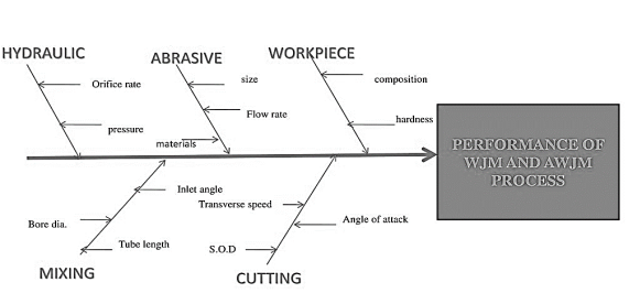
Fig. Process Parameters
- MRR depends on the reactive force F of the jet.
Reactive force = Mass flow rate (m) X jet velocity (v)
Hence,
MRR α m α v
- Depends on fluid pressure
- Depends on fluid pressure (p) and nozzle diameter
- In AJM, the material removal takes place due to impingement of the fine abrasive particles. These particles move with the high-speed air (or gas) stream.
- The abrasive particles are typically of 0.025 mm diameter and the air discharges at a pressure of several atmosphere.
Working of Abrasive jet machining (AJM):
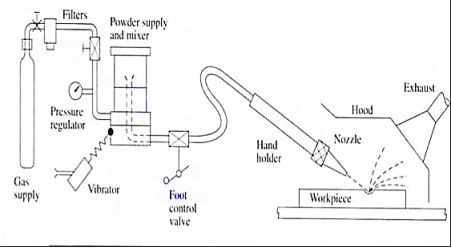
Fig. Abrasive jet machining
- The nozzle is made of a hard material like Tungsten Carbide here fine-grained abrasive particles are fed from the Hooper into the mixing chamber.
- High pressure air is forced in to the mixing chamber.
- The stream of abrasive particles bombards the work piece at a very high speed and removes the work material due to erosion.
- The abrasive particle feed rate is controlled by the amplitude of vibration of the mixing chamber.
Typical AJM Parameters
- Abrasive
- Aluminum oxide for Al and Brass.
- SiC for Stainless steel and Ceramic
- Bicarbonate of soda for Teflon
- Glass bed for polishing.
2. Size
- 10-15 Micron
3. Quantity
- 5-15 liter/min for fine work
- 10-30 liter/min for usual cuts.
- 50-100 liter/min for rough cuts
4. Medium
- Dry air, CO2, N2
- Quantity: 30 liter/min
- Velocity: 150-300 m/min
- Pressure: 200-1300 KPa
5. Nozzle
- Material: Tungsten carbide
- Stand of distance: 2.54-75 mm
- Diameter: 0.13-1.2 mm
- Operating Angle: 60° to vertical
6. Factors affecting MRR:
- Types of abrasive and abrasive grain size
- Flow rate
- Standoff distance
- Nozzle Pressure
The nozzle is one of the most vital elements controlling the process characteristics. Since it is continuously in contact with the abrasive grains flowing at a high speed, the material must be hard to avoid any significant wear.
One of the most important factors in AJM is the distance between the work surface and the tip of the nozzle, normally called the nozzle distance
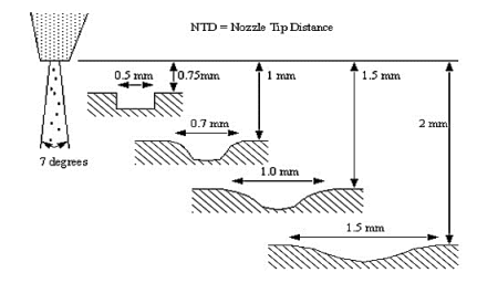
Fig. Nozzle Tip Distance
Applications: -
- For drilling holes of intricate shapes in hard and brittle materials.
- For machining fragile, brittle and heat sensitive materials.
- AJM can be used for drilling, cutting, deburring, cleaning and etching.
- Micro-machining of brittle materials.
Limitations: -
- MRR (Material removal rate) is rather low (around ~ 15 mm^3/min for machining glass).
- Abrasive particles tend to get embedded particularly if the work material is ductile. Tapering occurs due to flaring of the jet.
- Environmental load is rather high.
Advantages: -
- Extremely fast setup and programming.
- No start hole required.
- There is only one tool.
- Low capital cost.
- Less vibration.
- No heat generation in work piece.
- Environmentally Friendly.
Disadvantages: -
- Low metal removal rate.
- Abrasive powder cannot be reused.
- Tapper is also a problem
Principle of Ultrasonic machining (USM):
In this method with the help of piezoelectric transducer tool is vibrate at high frequency in a direction normal to the surface being machined abrasive slurry are used for the remove the metal from work piece.
Working of USM:
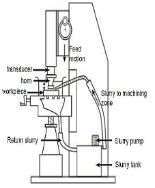
Fig. Ultrasonic machining
- The USM diagram shown in figure.
- In ultrasonic machining a tool vibrate longitudinally at 20 to 30 kHz with amplitude between 0.01 to 0.06 mm is pressed on to the work surface with light force.
- The electronic oscillator and amplifier are also known as generator.
- It converts the electrical energy of low frequency to high frequency.
- At the time high frequency current is passed through the coil therefore change in electromagnetic field which produces longitudinal strain.
- As the tool vibrate with specific frequency the abrasive slurry mix with water and grain of definite proportion is made to flow under pressure through the tool work piece interface. The flow of slurry through the work tool interface actually causes thousands of microscopic grains to remove the work material by abrasion.
Applications: -
- USM is best suitable for hard, brittle material, such as ceramics, carbides, glass, precious stone etc.
Advantages: -
- Any materials can be machined regardless of their electrical conductivity. Especially suitable for machining of brittle materials.
- Machined parts by USM possess better surface finish and higher structural integrity. USM does not produce thermal, electrical and chemical abnormal surface.
Disadvantages: -
- Tool wears fast in USM.
- Machining area and depth is restraint in USM.
- High cost of tooling.
- MMR is low.
References:
1. Kalpakjian and Schmid, Manufacturing processes for engineering materials (5th Edition)-Pearson India, 2014.
2. Mikell P. Groover, Fundamentals of Modern Manufacturing: Materials, Processes, and Systems.
3. Manufacturing Technology by P.N. Rao., MCGRAW HILL INDIA.
4. Materials and Manufacturing by Paul Degarmo.
5. Manufacturing Processes by Kaushish, PHI.
Unit - 5
Unconventional Machining Processes
- Abrasive jet machining (AJM) is one of the advanced machining processes (mechanical energy based) where a high velocity jet of abrasives is utilized to remove material from work surface by impact erosion. The abrasive jet is obtained by accelerating fine abrasive particles in highly pressurized gas (carrier gas). A nozzle is used to convert this pressure energy into kinetic energy and also to direct the jet towards work surface at a particular angle (impingement angle). Upon impact, hard abrasive particles gradually remove material by erosion and sometime assisted by brittle fracture.
- AJM differs from age old sand blasting technique by the achievable level of accuracy and precision. AJM utilizes various abrasives including alumina, silicon carbide, glass beads, sodium bicarbonate, etc.; whereas sand blasting predominantly utilizes only silica sand (SiO2). Although purposes of both the processes are quite identical, cutting parameters are often controlled precisely in AJM and thus it can provide better accuracy and precision.
Working Principle of Abrasive Jet Machining
- The fundamental principle of Abrasive jet machining involves the use of a high-speed stream of abrasive particles carried by a high-pressure gas or air on the work surface through a nozzle.
- The metal is removed because of erosion caused by the abrasive particles impacting the work surface at high speed. With repeated impacts, small bits of material get loosened and a fresh surface is exposed to the jet.
- This process is mainly employed for such machining works which are otherwise difficult, such as thin sections of hard metals and alloys, cutting of material which is sensitive of heat damage, producing intricate holes, deburring, etching, polishing etc.
Parts of Abrasive Jet machine
The figure shows a schematic diagram of the abrasive jet machine.
Gas Supply
The filtered gas, supplied under a pressure of 2 to 8 kgf/cm to the mixing chamber containing the abrasive powder and vibrating at 50 Hz entrains the abrasive particles and is then passed into a connecting hose. This abrasive and gas mixture emerges from a small nozzle mounted on a fixture at a high velocity ranging from 150 to 300 m/min.
Abrasive
Abrasive powder feed rate is controlled by the amplitude of vibration of the mixing chamber. The gas flow and pressure is controlled by a pressure regulator. To control the size and shape of the cut either the workpiece or the nozzle is moved by cams, pantographs or other suitable mechanisms.
The abrasives generally used are silicon carbide, aluminium oxide, glass powder or specially prepared sodium bicarbonate. The common particle sizes vary from 10 microns to 50 microns. Smaller sizes are used for good surface finish and precision work. While larger sizes are used for rapid removal rate.
In addition to the above abrasives, dolomite (calcium magnesium carbonate) of 200 grit size is found suitable for light cleaning and etching. Glass beads of diameter 0.30 to 0.60 mm are used for light polishing and deburring.
Nozzle
Nozzles have a great degree of abrasion wear, they’re made of hard materials such as tungsten carbide or synthetic sapphire to reduce the wear rate. Nozzles made of tungsten carbide have an average life of 8 to 12 hours. While nozzles of sapphire last for about 300 hours of operation when used with 27-micron abrasive powder. The gases used are nitrogen, carbon dioxide or clean air.
Workpiece
The metal removal rate depends upon the diameter of the nozzle, the composition of the abrasive gas mixture, the hardness of abrasive particles and that of work material, particle size, the velocity of jet and distance of the workpiece from the jet. A typical material removal rate for abrasive jet machining is 16 mm/min in cutting glass.
Working
- A typical set-up for abrasive jet machining is shown in the figure. The abrasive particles are held in a suitable holding device, like a tank and fed into the mixing chamber. A regulator is incorporated in the line to control the flow of abrasive particles compressed air or high-pressure gas is supplied to the mixing chamber through a pipeline.
- This pipeline carries a pressure gauge and a regulator to control the gas flow and its pressure. The mixing chamber, carrying the abrasive particles is vibrated and the amplitude of these vibrations controls the flow of abrasive particles.
- These particles mic in the gas stream, travel further through a hose and finally pass through the nozzle at a considerably high speed. This outgoing high-speed stream of the mixture of gas and abrasive particles is known as abrasive jet.
Accuracy
With close control of the various parameters, dimensional tolerance of +0.05 mm are often obtained. On normal production work, the accuracy of +0.1 mm is easily held.
Design consideration for AJM
Material removal is done with cutting speeds between 25 – 125 mm/min. |
Dimensional tolerances are in the range of ± 2 to ± 5 µm. |
Process parameters and their influence on AJM
- There are many factors that can influence abrasive jet machining performance. Important process parameters include (i) abrasive particles—its shape, size, strength, material and flow rate; (ii) carrier gas—its nature, composition, flow rate, pressure and temperature; (iii) abrasive jet—mixing ratio, striking velocity, impingement angle and stand-off distance; (iv) nozzle—its profile and inner diameter; and (v) work material—its mechanical properties and stress concentration.
- AJM performance is usually assessed by analyzing three output responses, namely
(i) material removal rate (MRR),
(ii) surface roughness and accuracy of machined feature, and
(iii) nozzle life or nozzle wear rate. Effects of process parameters on AJM performance are discussed below.
Effects of abrasives on AJM performance
- As discussed earlier, shape, size, strength, material and flow rate of abrasive can influence machining performance. Irregular shape abrasives having sharp edges tend to produce higher MRR as compared to spherical grits. Smaller size grits produce highly finished surface but reduce material removal rate (MRR) and thus productivity descends. Larger grits can again create trouble while mixing and flowing through the pipeline. However, variation in size in the entire volume should be low otherwise estimation or assessment will not be accurate.
- Abrasive materials have varying strength or hardness. The harder is the abrasive with respect to work surface hardness, the larger will be the volume removal rate. It is usually the relative hardness between abrasives and workpiece that determines machining capability and productivity.
Effects of carrier gas on AJM performance
- Carrier gas pressure and its flow rate are two paramount factors that determine performance and machining capability. Higher gas pressure reduces jet spreading and thus helps in cutting deeper slots accurately. However, various accessories including pipeline must be capable enough to handle such high pressure without failure. Moreover, increased gas flow rate gives the provision for utilizing higher abrasive flow rate, which can improve productivity.
Effects of mixing ratio on AJM performance
- Mixing ratio (M) is the ratio between mass flow rate of abrasive particles and mass flow rate of carrier gas. It usually determines concentration of abrasives in the jet. Mixing ratio are often increased by increasing abrasive percentage and in such case an increasing trend in MRR are often noticed because larger number of abrasives participates in micro-cutting action per unit time. However, excessive concentration of abrasive in the jet can significantly reduce MRR because of lower jet velocity (as gas pressure is constant) and unavoidable collision (thus loss of kinetic energy).
- MRR are often enhanced by proportionally increasing both the abrasive flow rate and gas flow rate at same rate in order that mixing ratio remains constant. In such case, higher pressure of the carrier gas has to be utilized. This necessitates thicker and stronger pipelines and other accessories to smoothly handle such high pressure without leakage and rupture. Indefinite increase in MRR is not practically feasible because of limited capability of equipment and accessories.
Effect of stand-off distance on AJM performance
- Distance from the work surface to the tip of nozzle in abrasive jet machining set-up is known as Stand-Off Distance, abbreviated as SOD. Higher SOD causes spreading of jet and thus its cross-sectional area increases with the sacrifice of jet velocity. As a consequent, machining deeper slots or hole becomes difficult; instead a wider area is cut. Alternatively smaller SOD can cut a deeper but narrow slot or hole. It also enhances MRR. Thus an optimum value of stand-off distance is required to set for obtaining satisfactory performance in abrasive jet machining.
Effect of impingement angle on AJM performance
- Impingement angle (θ), also known as spray angle or impact angle, is usually the angle between the work surface and abrasive jet axis. Practically it is kept between 60º – 90º in order to get satisfactory performance in AJM. Larger angle tends to create deeper penetration, while smaller angle tends to increase machining area. An impingement angle (θ) between 70º – 80º provides better result in terms of material removal rate in abrasive jet machining.
Material removal rate and its estimation
- Knowledge of material removal rate (MRR) is beneficial for selecting process parameters and choosing feed rate of the nozzle. It also facilitates accurate estimation of productivity, delivery time as well as production cost. Since only kinetic energy of abrasive grits is utilized for erosion, the analytical formula for MRR are often established by equating available kinetic energy with t he work done required for creating an indentation of certain cord length on a specific work material.
- However, ductile and brittle materials behave differently in indent formation, and thus size of indentation created by the impact of single abrasive grit is different for ductile and brittle materials.
Process capability of abrasive jet machining
- Materials: Hard and brittle material preferred.
- Surface finish: Down to 0.10µm achievable.
- Tolerance: ±0.10mm.
- Feature size: Minimum limit 0.10mm.
- Corner radius: Minimum limit 0.2mm.
- MRR: 15mm3/min.
- Cut thickness: 2 – 6mm plates based on material.
Advantages of abrasive jet machining
- Suitable for removal of deposits on surface
- Wide range of surface finish are often obtained
- Process is independent of electrical or thermal properties
- No thermal damage of workpiece
- Suitable for nonconductive brittle materials
- Low capital investment
Disadvantages of abrasive jet machining
- Not suitable for soft and ductile materials
- Abrasives are not reusable
- Abrasive collection and disposal are problematic
- Inaccurate cutting and drilling (stray cutting)
- Limited nozzle life
Applications of AJM
- Abrasive jet machining is often advantageously utilized for multifarious purposes including surface cleaning, deburring, abrading and even making holes. Common applications of abrasive jet machining process are provided below. It is to be noted that, irrespective of the purpose, abrasive jet machining (AJM) is beneficial only for hard and brittle materials. AJM should be avoided if work material is soft and ductile; otherwise quality of machined surface will be poor.
- Work surface cleaning—AJM are often advantageously used for cleaning metallic or ceramic surfaces (substrate must be hard). Such cleaning processes include removal of oxide, paint, coating, stain, glue, loose sand particles, etc.
- Deflashing and trimming—Controlled abrasive jet machining are often utilized for removing flash to get desired clean product with higher dimensional accuracy and tolerance as well as sumptuous appearance.
- Engraving—As an alternative to laser beam machining, abrasive jet machining can also be applied for incising purposes irrespective of chemical and electrical properties of work material.
- Ceramic abrading and glass frosting—Very hard materials including glass, refractory, stone, etc. are often easily abraded by AJM in order to get finished surface having tight tolerance.
- Deburring—Abrasive jet machining is one of the efficient methods for deburring (process for removal of burr) of milled features and drilled holes, especially when work material is hard.
- Cutting and drilling hole—AJM can also be utilized for cutting various shapes as well as for drilling holes. However, holes, slots or pockets may lack accuracy as sharp corners cannot be obtained by this process.
- Water Jet Machining (WJM) is a mechanical energy based non-traditional machining process used to cut and machine soft and non-metallic materials.
- It involves the use of high velocity water jet to smoothly cut a soft workpiece. It is similar to Abrasive Jet Machining (AJM).
- In water jet machining, high velocity water jet is allowed to strike a given workpiece. During this process, its kinetic energy is converted to pressure energy. This induces a stress on the workpiece. When this induced stress is high enough, unwanted particles of the workpiece are automatically removed.
Construction:
- Water from the reservoir is pumped to the intensifier using a hydraulic pump.
- The intensifier increases the pressure of the water to the required level. Usually, the water is pressurized to 200 to 400 MPa.
- Pressurized water is then sent to the accumulator. The accumulator temporarily stores the pressurized water.
- Pressurized water then enters the nozzle by passing through the control valve and flow regulator.
- Control valve controls the direction of water and limits the pressure of water under permissible limits.
- Flow regulator regulates and controls the flow rate of water.
- Pressurized water finally enters the nozzle. Here, it expands with a tremendous increase in its kinetic energy. High velocity water jet is produced by the nozzle.
- When this water jet strikes the workpiece, stresses are induced. These stresses are used to remove material from the workpiece.
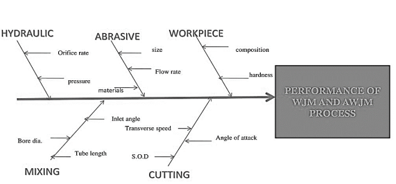
Fig. Process Parameters
- MRR depends on the reactive force F of the jet.
Reactive force = Mass flow rate (m) X jet velocity (v)
Hence,
MRR α m α v
- Depends on fluid pressure
- Depends on fluid pressure (p) and nozzle diameter
- In AJM, the material removal takes place due to impingement of the fine abrasive particles. These particles move with the high-speed air (or gas) stream.
- The abrasive particles are typically of 0.025 mm diameter and the air discharges at a pressure of several atmosphere.
Working of Abrasive jet machining (AJM):
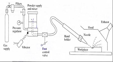
Fig. Abrasive jet machining
- The nozzle is made of a hard material like Tungsten Carbide here fine-grained abrasive particles are fed from the Hooper into the mixing chamber.
- High pressure air is forced in to the mixing chamber.
- The stream of abrasive particles bombards the work piece at a very high speed and removes the work material due to erosion.
- The abrasive particle feed rate is controlled by the amplitude of vibration of the mixing chamber.
Typical AJM Parameters
- Abrasive
- Aluminum oxide for Al and Brass.
- SiC for Stainless steel and Ceramic
- Bicarbonate of soda for Teflon
- Glass bed for polishing.
2. Size
- 10-15 Micron
3. Quantity
- 5-15 liter/min for fine work
- 10-30 liter/min for usual cuts.
- 50-100 liter/min for rough cuts
4. Medium
- Dry air, CO2, N2
- Quantity: 30 liter/min
- Velocity: 150-300 m/min
- Pressure: 200-1300 KPa
5. Nozzle
- Material: Tungsten carbide
- Stand of distance: 2.54-75 mm
- Diameter: 0.13-1.2 mm
- Operating Angle: 60° to vertical
6. Factors affecting MRR:
- Types of abrasive and abrasive grain size
- Flow rate
- Standoff distance
- Nozzle Pressure
The nozzle is one of the most vital elements controlling the process characteristics. Since it is continuously in contact with the abrasive grains flowing at a high speed, the material must be hard to avoid any significant wear.
One of the most important factors in AJM is the distance between the work surface and the tip of the nozzle, normally called the nozzle distance
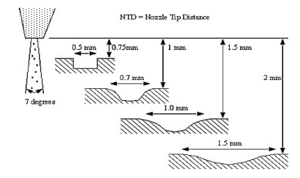
Fig. Nozzle Tip Distance
Applications: -
- For drilling holes of intricate shapes in hard and brittle materials.
- For machining fragile, brittle and heat sensitive materials.
- AJM can be used for drilling, cutting, deburring, cleaning and etching.
- Micro-machining of brittle materials.
Limitations: -
- MRR (Material removal rate) is rather low (around ~ 15 mm^3/min for machining glass).
- Abrasive particles tend to get embedded particularly if the work material is ductile. Tapering occurs due to flaring of the jet.
- Environmental load is rather high.
Advantages: -
- Extremely fast setup and programming.
- No start hole required.
- There is only one tool.
- Low capital cost.
- Less vibration.
- No heat generation in work piece.
- Environmentally Friendly.
Disadvantages: -
- Low metal removal rate.
- Abrasive powder cannot be reused.
- Tapper is also a problem
Principle of Ultrasonic machining (USM):
In this method with the help of piezoelectric transducer tool is vibrate at high frequency in a direction normal to the surface being machined abrasive slurry are used for the remove the metal from work piece.
Working of USM:
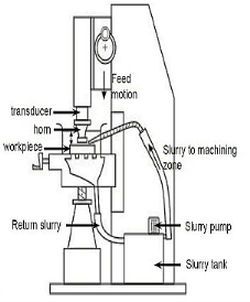
Fig. Ultrasonic machining
- The USM diagram shown in figure.
- In ultrasonic machining a tool vibrate longitudinally at 20 to 30 kHz with amplitude between 0.01 to 0.06 mm is pressed on to the work surface with light force.
- The electronic oscillator and amplifier are also known as generator.
- It converts the electrical energy of low frequency to high frequency.
- At the time high frequency current is passed through the coil therefore change in electromagnetic field which produces longitudinal strain.
- As the tool vibrate with specific frequency the abrasive slurry mix with water and grain of definite proportion is made to flow under pressure through the tool work piece interface. The flow of slurry through the work tool interface actually causes thousands of microscopic grains to remove the work material by abrasion.
Applications: -
- USM is best suitable for hard, brittle material, such as ceramics, carbides, glass, precious stone etc.
Advantages: -
- Any materials can be machined regardless of their electrical conductivity. Especially suitable for machining of brittle materials.
- Machined parts by USM possess better surface finish and higher structural integrity. USM does not produce thermal, electrical and chemical abnormal surface.
Disadvantages: -
- Tool wears fast in USM.
- Machining area and depth is restraint in USM.
- High cost of tooling.
- MMR is low.
References:
1. Kalpakjian and Schmid, Manufacturing processes for engineering materials (5th Edition)-Pearson India, 2014.
2. Mikell P. Groover, Fundamentals of Modern Manufacturing: Materials, Processes, and Systems.
3. Manufacturing Technology by P.N. Rao., MCGRAW HILL INDIA.
4. Materials and Manufacturing by Paul Degarmo.
5. Manufacturing Processes by Kaushish, PHI.
Unit - 5
Unconventional Machining Processes
Unit - 5
Unconventional Machining Processes
- Abrasive jet machining (AJM) is one of the advanced machining processes (mechanical energy based) where a high velocity jet of abrasives is utilized to remove material from work surface by impact erosion. The abrasive jet is obtained by accelerating fine abrasive particles in highly pressurized gas (carrier gas). A nozzle is used to convert this pressure energy into kinetic energy and also to direct the jet towards work surface at a particular angle (impingement angle). Upon impact, hard abrasive particles gradually remove material by erosion and sometime assisted by brittle fracture.
- AJM differs from age old sand blasting technique by the achievable level of accuracy and precision. AJM utilizes various abrasives including alumina, silicon carbide, glass beads, sodium bicarbonate, etc.; whereas sand blasting predominantly utilizes only silica sand (SiO2). Although purposes of both the processes are quite identical, cutting parameters are often controlled precisely in AJM and thus it can provide better accuracy and precision.
Working Principle of Abrasive Jet Machining
- The fundamental principle of Abrasive jet machining involves the use of a high-speed stream of abrasive particles carried by a high-pressure gas or air on the work surface through a nozzle.
- The metal is removed because of erosion caused by the abrasive particles impacting the work surface at high speed. With repeated impacts, small bits of material get loosened and a fresh surface is exposed to the jet.
- This process is mainly employed for such machining works which are otherwise difficult, such as thin sections of hard metals and alloys, cutting of material which is sensitive of heat damage, producing intricate holes, deburring, etching, polishing etc.
Parts of Abrasive Jet machine
The figure shows a schematic diagram of the abrasive jet machine.
Gas Supply
The filtered gas, supplied under a pressure of 2 to 8 kgf/cm to the mixing chamber containing the abrasive powder and vibrating at 50 Hz entrains the abrasive particles and is then passed into a connecting hose. This abrasive and gas mixture emerges from a small nozzle mounted on a fixture at a high velocity ranging from 150 to 300 m/min.
Abrasive
Abrasive powder feed rate is controlled by the amplitude of vibration of the mixing chamber. The gas flow and pressure is controlled by a pressure regulator. To control the size and shape of the cut either the workpiece or the nozzle is moved by cams, pantographs or other suitable mechanisms.
The abrasives generally used are silicon carbide, aluminium oxide, glass powder or specially prepared sodium bicarbonate. The common particle sizes vary from 10 microns to 50 microns. Smaller sizes are used for good surface finish and precision work. While larger sizes are used for rapid removal rate.
In addition to the above abrasives, dolomite (calcium magnesium carbonate) of 200 grit size is found suitable for light cleaning and etching. Glass beads of diameter 0.30 to 0.60 mm are used for light polishing and deburring.
Nozzle
Nozzles have a great degree of abrasion wear, they’re made of hard materials such as tungsten carbide or synthetic sapphire to reduce the wear rate. Nozzles made of tungsten carbide have an average life of 8 to 12 hours. While nozzles of sapphire last for about 300 hours of operation when used with 27-micron abrasive powder. The gases used are nitrogen, carbon dioxide or clean air.
Workpiece
The metal removal rate depends upon the diameter of the nozzle, the composition of the abrasive gas mixture, the hardness of abrasive particles and that of work material, particle size, the velocity of jet and distance of the workpiece from the jet. A typical material removal rate for abrasive jet machining is 16 mm/min in cutting glass.
Working
- A typical set-up for abrasive jet machining is shown in the figure. The abrasive particles are held in a suitable holding device, like a tank and fed into the mixing chamber. A regulator is incorporated in the line to control the flow of abrasive particles compressed air or high-pressure gas is supplied to the mixing chamber through a pipeline.
- This pipeline carries a pressure gauge and a regulator to control the gas flow and its pressure. The mixing chamber, carrying the abrasive particles is vibrated and the amplitude of these vibrations controls the flow of abrasive particles.
- These particles mic in the gas stream, travel further through a hose and finally pass through the nozzle at a considerably high speed. This outgoing high-speed stream of the mixture of gas and abrasive particles is known as abrasive jet.
Accuracy
With close control of the various parameters, dimensional tolerance of +0.05 mm are often obtained. On normal production work, the accuracy of +0.1 mm is easily held.
Design consideration for AJM
Material removal is done with cutting speeds between 25 – 125 mm/min. |
Dimensional tolerances are in the range of ± 2 to ± 5 µm. |
Process parameters and their influence on AJM
- There are many factors that can influence abrasive jet machining performance. Important process parameters include (i) abrasive particles—its shape, size, strength, material and flow rate; (ii) carrier gas—its nature, composition, flow rate, pressure and temperature; (iii) abrasive jet—mixing ratio, striking velocity, impingement angle and stand-off distance; (iv) nozzle—its profile and inner diameter; and (v) work material—its mechanical properties and stress concentration.
- AJM performance is usually assessed by analyzing three output responses, namely
(i) material removal rate (MRR),
(ii) surface roughness and accuracy of machined feature, and
(iii) nozzle life or nozzle wear rate. Effects of process parameters on AJM performance are discussed below.
Effects of abrasives on AJM performance
- As discussed earlier, shape, size, strength, material and flow rate of abrasive can influence machining performance. Irregular shape abrasives having sharp edges tend to produce higher MRR as compared to spherical grits. Smaller size grits produce highly finished surface but reduce material removal rate (MRR) and thus productivity descends. Larger grits can again create trouble while mixing and flowing through the pipeline. However, variation in size in the entire volume should be low otherwise estimation or assessment will not be accurate.
- Abrasive materials have varying strength or hardness. The harder is the abrasive with respect to work surface hardness, the larger will be the volume removal rate. It is usually the relative hardness between abrasives and workpiece that determines machining capability and productivity.
Effects of carrier gas on AJM performance
- Carrier gas pressure and its flow rate are two paramount factors that determine performance and machining capability. Higher gas pressure reduces jet spreading and thus helps in cutting deeper slots accurately. However, various accessories including pipeline must be capable enough to handle such high pressure without failure. Moreover, increased gas flow rate gives the provision for utilizing higher abrasive flow rate, which can improve productivity.
Effects of mixing ratio on AJM performance
- Mixing ratio (M) is the ratio between mass flow rate of abrasive particles and mass flow rate of carrier gas. It usually determines concentration of abrasives in the jet. Mixing ratio are often increased by increasing abrasive percentage and in such case an increasing trend in MRR are often noticed because larger number of abrasives participates in micro-cutting action per unit time. However, excessive concentration of abrasive in the jet can significantly reduce MRR because of lower jet velocity (as gas pressure is constant) and unavoidable collision (thus loss of kinetic energy).
- MRR are often enhanced by proportionally increasing both the abrasive flow rate and gas flow rate at same rate in order that mixing ratio remains constant. In such case, higher pressure of the carrier gas has to be utilized. This necessitates thicker and stronger pipelines and other accessories to smoothly handle such high pressure without leakage and rupture. Indefinite increase in MRR is not practically feasible because of limited capability of equipment and accessories.
Effect of stand-off distance on AJM performance
- Distance from the work surface to the tip of nozzle in abrasive jet machining set-up is known as Stand-Off Distance, abbreviated as SOD. Higher SOD causes spreading of jet and thus its cross-sectional area increases with the sacrifice of jet velocity. As a consequent, machining deeper slots or hole becomes difficult; instead a wider area is cut. Alternatively smaller SOD can cut a deeper but narrow slot or hole. It also enhances MRR. Thus an optimum value of stand-off distance is required to set for obtaining satisfactory performance in abrasive jet machining.
Effect of impingement angle on AJM performance
- Impingement angle (θ), also known as spray angle or impact angle, is usually the angle between the work surface and abrasive jet axis. Practically it is kept between 60º – 90º in order to get satisfactory performance in AJM. Larger angle tends to create deeper penetration, while smaller angle tends to increase machining area. An impingement angle (θ) between 70º – 80º provides better result in terms of material removal rate in abrasive jet machining.
Material removal rate and its estimation
- Knowledge of material removal rate (MRR) is beneficial for selecting process parameters and choosing feed rate of the nozzle. It also facilitates accurate estimation of productivity, delivery time as well as production cost. Since only kinetic energy of abrasive grits is utilized for erosion, the analytical formula for MRR are often established by equating available kinetic energy with t he work done required for creating an indentation of certain cord length on a specific work material.
- However, ductile and brittle materials behave differently in indent formation, and thus size of indentation created by the impact of single abrasive grit is different for ductile and brittle materials.
Process capability of abrasive jet machining
- Materials: Hard and brittle material preferred.
- Surface finish: Down to 0.10µm achievable.
- Tolerance: ±0.10mm.
- Feature size: Minimum limit 0.10mm.
- Corner radius: Minimum limit 0.2mm.
- MRR: 15mm3/min.
- Cut thickness: 2 – 6mm plates based on material.
Advantages of abrasive jet machining
- Suitable for removal of deposits on surface
- Wide range of surface finish are often obtained
- Process is independent of electrical or thermal properties
- No thermal damage of workpiece
- Suitable for nonconductive brittle materials
- Low capital investment
Disadvantages of abrasive jet machining
- Not suitable for soft and ductile materials
- Abrasives are not reusable
- Abrasive collection and disposal are problematic
- Inaccurate cutting and drilling (stray cutting)
- Limited nozzle life
Applications of AJM
- Abrasive jet machining is often advantageously utilized for multifarious purposes including surface cleaning, deburring, abrading and even making holes. Common applications of abrasive jet machining process are provided below. It is to be noted that, irrespective of the purpose, abrasive jet machining (AJM) is beneficial only for hard and brittle materials. AJM should be avoided if work material is soft and ductile; otherwise quality of machined surface will be poor.
- Work surface cleaning—AJM are often advantageously used for cleaning metallic or ceramic surfaces (substrate must be hard). Such cleaning processes include removal of oxide, paint, coating, stain, glue, loose sand particles, etc.
- Deflashing and trimming—Controlled abrasive jet machining are often utilized for removing flash to get desired clean product with higher dimensional accuracy and tolerance as well as sumptuous appearance.
- Engraving—As an alternative to laser beam machining, abrasive jet machining can also be applied for incising purposes irrespective of chemical and electrical properties of work material.
- Ceramic abrading and glass frosting—Very hard materials including glass, refractory, stone, etc. are often easily abraded by AJM in order to get finished surface having tight tolerance.
- Deburring—Abrasive jet machining is one of the efficient methods for deburring (process for removal of burr) of milled features and drilled holes, especially when work material is hard.
- Cutting and drilling hole—AJM can also be utilized for cutting various shapes as well as for drilling holes. However, holes, slots or pockets may lack accuracy as sharp corners cannot be obtained by this process.
- Water Jet Machining (WJM) is a mechanical energy based non-traditional machining process used to cut and machine soft and non-metallic materials.
- It involves the use of high velocity water jet to smoothly cut a soft workpiece. It is similar to Abrasive Jet Machining (AJM).
- In water jet machining, high velocity water jet is allowed to strike a given workpiece. During this process, its kinetic energy is converted to pressure energy. This induces a stress on the workpiece. When this induced stress is high enough, unwanted particles of the workpiece are automatically removed.
Construction:
- Water from the reservoir is pumped to the intensifier using a hydraulic pump.
- The intensifier increases the pressure of the water to the required level. Usually, the water is pressurized to 200 to 400 MPa.
- Pressurized water is then sent to the accumulator. The accumulator temporarily stores the pressurized water.
- Pressurized water then enters the nozzle by passing through the control valve and flow regulator.
- Control valve controls the direction of water and limits the pressure of water under permissible limits.
- Flow regulator regulates and controls the flow rate of water.
- Pressurized water finally enters the nozzle. Here, it expands with a tremendous increase in its kinetic energy. High velocity water jet is produced by the nozzle.
- When this water jet strikes the workpiece, stresses are induced. These stresses are used to remove material from the workpiece.
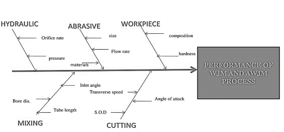
Fig. Process Parameters
- MRR depends on the reactive force F of the jet.
Reactive force = Mass flow rate (m) X jet velocity (v)
Hence,
MRR α m α v
- Depends on fluid pressure
- Depends on fluid pressure (p) and nozzle diameter
- In AJM, the material removal takes place due to impingement of the fine abrasive particles. These particles move with the high-speed air (or gas) stream.
- The abrasive particles are typically of 0.025 mm diameter and the air discharges at a pressure of several atmosphere.
Working of Abrasive jet machining (AJM):
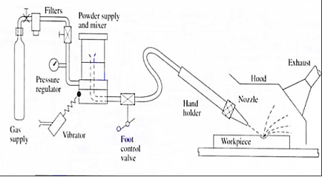
Fig. Abrasive jet machining
- The nozzle is made of a hard material like Tungsten Carbide here fine-grained abrasive particles are fed from the Hooper into the mixing chamber.
- High pressure air is forced in to the mixing chamber.
- The stream of abrasive particles bombards the work piece at a very high speed and removes the work material due to erosion.
- The abrasive particle feed rate is controlled by the amplitude of vibration of the mixing chamber.
Typical AJM Parameters
- Abrasive
- Aluminum oxide for Al and Brass.
- SiC for Stainless steel and Ceramic
- Bicarbonate of soda for Teflon
- Glass bed for polishing.
2. Size
- 10-15 Micron
3. Quantity
- 5-15 liter/min for fine work
- 10-30 liter/min for usual cuts.
- 50-100 liter/min for rough cuts
4. Medium
- Dry air, CO2, N2
- Quantity: 30 liter/min
- Velocity: 150-300 m/min
- Pressure: 200-1300 KPa
5. Nozzle
- Material: Tungsten carbide
- Stand of distance: 2.54-75 mm
- Diameter: 0.13-1.2 mm
- Operating Angle: 60° to vertical
6. Factors affecting MRR:
- Types of abrasive and abrasive grain size
- Flow rate
- Standoff distance
- Nozzle Pressure
The nozzle is one of the most vital elements controlling the process characteristics. Since it is continuously in contact with the abrasive grains flowing at a high speed, the material must be hard to avoid any significant wear.
One of the most important factors in AJM is the distance between the work surface and the tip of the nozzle, normally called the nozzle distance
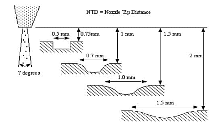
Fig. Nozzle Tip Distance
Applications: -
- For drilling holes of intricate shapes in hard and brittle materials.
- For machining fragile, brittle and heat sensitive materials.
- AJM can be used for drilling, cutting, deburring, cleaning and etching.
- Micro-machining of brittle materials.
Limitations: -
- MRR (Material removal rate) is rather low (around ~ 15 mm^3/min for machining glass).
- Abrasive particles tend to get embedded particularly if the work material is ductile. Tapering occurs due to flaring of the jet.
- Environmental load is rather high.
Advantages: -
- Extremely fast setup and programming.
- No start hole required.
- There is only one tool.
- Low capital cost.
- Less vibration.
- No heat generation in work piece.
- Environmentally Friendly.
Disadvantages: -
- Low metal removal rate.
- Abrasive powder cannot be reused.
- Tapper is also a problem
Principle of Ultrasonic machining (USM):
In this method with the help of piezoelectric transducer tool is vibrate at high frequency in a direction normal to the surface being machined abrasive slurry are used for the remove the metal from work piece.
Working of USM:
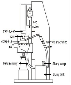
Fig. Ultrasonic machining
- The USM diagram shown in figure.
- In ultrasonic machining a tool vibrate longitudinally at 20 to 30 kHz with amplitude between 0.01 to 0.06 mm is pressed on to the work surface with light force.
- The electronic oscillator and amplifier are also known as generator.
- It converts the electrical energy of low frequency to high frequency.
- At the time high frequency current is passed through the coil therefore change in electromagnetic field which produces longitudinal strain.
- As the tool vibrate with specific frequency the abrasive slurry mix with water and grain of definite proportion is made to flow under pressure through the tool work piece interface. The flow of slurry through the work tool interface actually causes thousands of microscopic grains to remove the work material by abrasion.
Applications: -
- USM is best suitable for hard, brittle material, such as ceramics, carbides, glass, precious stone etc.
Advantages: -
- Any materials can be machined regardless of their electrical conductivity. Especially suitable for machining of brittle materials.
- Machined parts by USM possess better surface finish and higher structural integrity. USM does not produce thermal, electrical and chemical abnormal surface.
Disadvantages: -
- Tool wears fast in USM.
- Machining area and depth is restraint in USM.
- High cost of tooling.
- MMR is low.
References:
1. Kalpakjian and Schmid, Manufacturing processes for engineering materials (5th Edition)-Pearson India, 2014.
2. Mikell P. Groover, Fundamentals of Modern Manufacturing: Materials, Processes, and Systems.
3. Manufacturing Technology by P.N. Rao., MCGRAW HILL INDIA.
4. Materials and Manufacturing by Paul Degarmo.
5. Manufacturing Processes by Kaushish, PHI.