Unit - 6
Electrical Discharge Machining
Principle of EDM:
Electrical discharge machining (EDM), sometimes also referred to as spark machining, spark eroding, burning, die sinking, wire burning or wire erosion, is a manufacturing process whereby a desired shape is obtained using electrical discharges (sparks).
Material is removed from the work piece by a series of rapidly recurring current discharges between two electrodes, separated by a die-electric liquid and subject to an electric voltage. One of the electrodes is called the tool-electrode, or simply the "tool" or "electrode", while the other is called the workpiece- electrode, or "workpiece".
Working of EDM:
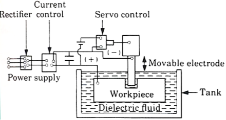
Fig. Electrical discharge machining
- The diagram of electro discharge machining shown in figure.
- EDM is thermal erosion process whereby material is melted and vaporized from an electrically conductive work piece immerse in a liquid dielectric with a series of spark discharge between the tool electrode and the work piece created by a power supply.
- The electrode and the work piece are separated by a dielectric medium.
- The dielectric medium is like as kerosene, paraffin or light oil.
- The strong electrostatic field between the electrode and work piece produce emission of electrons from the cathode.
- In this gap between tool and work piece get ionized. The liquid is force to sparking zone.
- Due to high temperature, the metal at the sparking zone melts instantaneously.
- The material of the tool is usually a material which conduct electricity and which can be easily shaped.
Advantages: -
- Smaller holes can be easy machined.
- No contact between tool and work piece then tool life is increase.
- Any complex shape can be machined.
Disadvantages: -
- Tool life is no longer.
- Power consumption is high.
- Cycle time is more
Surface finish:
The outermost boundary of a body adjacent to the air is called surface. When this surface deformed by a sharp cutting edge, the term surface finish describes the boundary.
A good surface is affected by many variables in single or multiple point machining.
Surface finish is defined in terms of 4 factors:
- Roughness – closely spaced surface irregularities, resulting from the manufacturing process or tools.
- Lay – the overall direction of the roughness pattern which can be affected by the machine and setup.
- Waviness – longer spaced irregularities caused by machine vibration and material warping among other factors.
- Flaws – unique surface imperfections in the material or processing.
Tool wear:
Tool subjected to:
1. Forces
2. Temperature
3. Sliding action
- After continuous use for some time, tool gives unsatisfactory or inefficient performance.
- Unsatisfactory or inefficient performance is due to “Tool Wear or Tool failure”. Consequences:
1. Loss of dimensional accuracy
2. Increased surface roughness
3. Increased power requirement
4. Excessive vibration and abnormal sound (Chatter)
5. Total breakage of the tool
Tool is replaced or reconditioned usually by grinding.
Tool Wear depending factors:
1. Type of tool material and its hardness
2. Type and condition of work piece material
3. Dimensions of cut (Feed and depth of cut)
4. Cutting speed
5. Tool geometry
6. Tool temperature (function of cutting speed, feed and depth of cut)
7. Type of cutting fluid
Classification of Tool Wear
1. Flank wear
2. Crater wear on tool face
3. Localized wear such as the rounding of Cutting edge
4. Chipping of the cutting edge
The main components in EDM:
- Electric power supply
- Dielectric medium
- Work piece & tool
- Servo control unit.
- The work piece and tool are electrically connected to a DC power supply.
- The current density in the discharge of the channel is of the order of 10000 A/cm2 and power density is nearly 500 MW/cm2.
- A gap, known as SPARK GAP in the range, from 0.005 mm to 0.05 mm is maintained between the work piece and the tool.
- Dielectric slurry is forced through this gap at a pressure of 2 kgf/cm2 or lesser.
Working Principle:
- It is a process of metal removal based on the principle of material removal by an interrupted electric spark discharge between the electrode tool and the work piece.
- In EDM, a potential difference is applied between the tool and workpiece.
- Both tool and work material are to be conductors.
- The tool and work material are immersed in a dielectric medium.
- Generally, kerosene or deionized water is used as the dielectric medium.
- A gap is maintained between the tool and the workpiece.
- Depending upon the applied potential difference (50 to 450 V) and the gap between the tool and workpiece, an electric field would be established.
- Generally, the tool is connected to the negative terminal (cathode) of the generator and the workpiece is connected to positive terminal (anode).
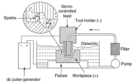
Fig. EDM Schematic
Power & Control Circuits:
Two broad categories of generators (power supplies) are in use on EDM. Commercially available: RC circuits based and transistor-controlled pulses.
In the first category, the main parameters to choose from a setup time are the resistance(s) of the resistor(s) and the capacitance(s) of the capacitor(s).
In an ideal condition, these quantities would affect the maximum current delivered in a discharge.
Current delivery in a discharge is associated with the charge accumulated on the capacitors at a certain moment.
Little control is expected over the time of discharge, which is likely to depend on the actual spark-gap conditions.
Advantage: RC circuit generator can allow the use of short discharge time more easily than the pulse-controlled generator.
Also, the open circuit voltage (i.e., voltage between electrodes when dielectric is not broken) can be identified as steady state voltage of the RC circuit.
In generators based on transistor control, the user is usually able to deliver a train of voltage pulses to the electrodes.
Each pulse can be controlled in shape, for instance, quasi-rectangular.
In particular, the time between two consecutive pulses and the duration of each pulse can be set.
The amplitude of each pulse constitutes the open circuit voltage.
Thus, maximum duration of discharge is equal to duration of a voltage pulse. Maximum current during a discharge that the generator delivers can also be controlled.
Details of generators and control systems on EDMs are not always easily available to their user.
This is a barrier to describing the technological parameters of EDM process. Moreover, the parameters affecting the phenomena occurring between tool and electrode are also related to the motion controller of the electrodes.
A framework to define and measure the electrical parameters during an EDM operation directly on inter-electrode volume with an oscilloscope external to the machine has been recently proposed by Ferri et al.
This would enable the user to estimate directly the electrical parameter that affect their operations without relying upon machine manufacturer's claims.
When machining different materials in the same setup conditions, the actual electrical parameters are significantly different.
When using RC generators, the voltage pulses, shown in Fig. Are responsible for material removal.
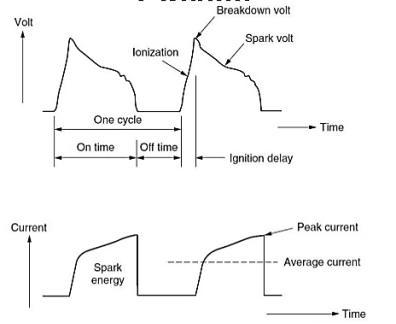
Fig. Voltage and current waveform during EDM
Wire EDM:
- This process is similar to contour cutting with a band saw.
- A slow-moving wire travels along a prescribed path, cutting the work piece with discharge sparks.
- Wire should have sufficient tensile strength and fracture toughness.
- Wire is made of brass, copper or tungsten. (About 0.25mm in diameter).
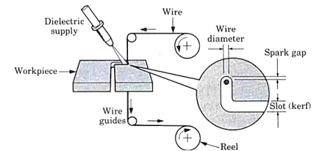
Fig. Wire EDM
- Electrochemical Machining (ECM) is one of the newest and most useful non-traditional machining (NTM) process belonging to Electrochemical category.
- Electrochemical machining (ECM) is used to remove metal and alloys which are difficult or impossible to machine by mechanical machining process.
- The reverse of electroplating.
- This machining process is based Michael Faraday’s classical laws of electrolysis, requiring basically two electrodes, an electrolyte, a gap and a source of D.C power of sufficient capacity.
Working of ECM:
- In the actual process of ECM, the cathode is tool shaped (mirror image of work-piece) and anode is the work-piece.
- A gap (0.05 to 0.7 mm) is provided between the tool and work-piece and electrolyte flows through the gap at a velocity of 30 to 60 m/s and it completes the electrical circuit.
- Electrolyte is pumped at high pressure of 20 kgf/
 (1.96 MPa) through the gap.
 - Electrolyte must be circulated at a rate sufficiently high to conduct current between them and to carry heat.
- Metal is removed from the work-piece by dissolution
- The electric current is of the order of 50 to 40,000 A at 5 to 35 V D.C for current density of 20 to 300 A/
 .
. - Power of 3 KWh is needed to remove 16
 of metal which is almost 30 times the energy required in the conventional process (when the material is readily machinable).
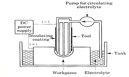
Fig. Electro-chemical machining
Advantages of ECM:
- Process leaves a burr free surface.
- Does not cause any thermal damage to the parts.
- Lack of tool force prevents distortion of parts.
- Capable of machining complex parts and hard materials.
- ECM systems are now available as Numerically Controlled machining centers with capability for high production, high flexibility and high tolerances.
Types of masks used in Chemical machining:
- Cut and peel masks.
- Screen resist masks.
- Photo resist masks.
- Cut and peel maskants:
- Film of chemically resistant material is applied to the work piece by dipping, spraying or flow coating.
- Vinyl, styrene and buta diene are used.
- Rubbery film is then cut & peeled away selectively.
- Manual scribing of mask material usually achieves an accuracy of ±0.13 mm to ±0.75 mm.
2. Screen resist maskants:
- Mask material is applied to the work piece surface by printing, using stencils and a fine polyester or stainless-steel mesh screen.
- Relatively thin coatings with tolerances held to ±0.05 to ±0.18 mm is obtained by screen printing.
- Etching depths are restricted to about 1.5 mm because of thinness of the coating.
3. Photo resist maskants:
- Photo resist mask is quite widely used & is often referred to as photochemical machining.
- Produces intricate & finely detailed shapes using a light activated resist materials.
- WP coated with photo resist material & a master transparency is held against the WP, while exposure to UV rays takes place.
- Light activates the photo resist material in those areas corresponding to opaque parts.
- Tolerances of ±0.025 to 0.005 mm can be produced.
The general requirements of tool material in ECM are:
1. It should be conductor of electricity.
2. It should be rigid enough to take up the load due to fluid pressure.
3. It should be chemically inert to the electrolyte.
4. It should be easily machinable to make it in the desired shape.
Process Parameter:
S.no | Parameters | Values |
1. | Power Supply |
|
| Type | Direct Current |
| Voltage | 2 to 35 V |
| Current | 50 to 40,000 A |
| Current Density | 0.1 A/mm2 to 5 A/mm2 |
2. | Electrolyte |
|
| Material | NaCl and NaNO3 |
| Temperature | 20 oC to 50 oC |
| Flow rate | 20 lpm/100 A current |
| Pressure | 0.5 to 20 bars |
| Dilution | 100 g/l to 500 g/l |
3. | Working gap | 0.1 mm to 2mm |
4. | Overcut | 0.2 mm to 3 mm |
5. | Feed rate | 0.5 mm/min to 15 mm/min |
6. | Electrode material | Copper, brass and bronze |
7. | Surface roughness (Ra) | 0.2 to 1.5 μm |
Material removal rate (MRR):
- Material removal rate (MRR) is an important characteristic to evaluate efficiency of a non-traditional machining process.
- In ECM, material removal takes place due to atomic dissolution of work material which is governed by Faraday’s laws of Electrolysis.
MRR = m / tρ = IA / Fρν
Where m = ItA/Fv = mass of material dissolve
I = current
A = Atomic weight
v = valency
F = Faraday’s constant = 96500 coulombs
ρ = density of the material
Power Supply:
1. Type: direct current
2. Voltage: 2 to 35 V
3. Current: 50 to 40,000 A
4. Current density: 20 A/cm2 to 300 A/cm2
Surface finish is defined in terms of 4 factors:
- Roughness – closely spaced surface irregularities, resulting from the manufacturing process or tools.
- Lay – the overall direction of the roughness pattern which can be affected by the machine and setup.
- Waviness – longer spaced irregularities caused by machine vibration and material warping among other factors.
- Flaws – unique surface imperfections in the material or processing.
References:
1. Kalpakjian and Schmid, Manufacturing processes for engineering materials (5th Edition)-Pearson India, 2014.
2. Mikell P. Groover, Fundamentals of Modern Manufacturing: Materials, Processes, and Systems.
3. Manufacturing Technology by P.N. Rao., MCGRAW HILL INDIA.
4. Materials and Manufacturing by Paul Degarmo.
5. Manufacturing Processes by Kaushish, PHI.
Unit - 6
Electrical Discharge Machining
Principle of EDM:
Electrical discharge machining (EDM), sometimes also referred to as spark machining, spark eroding, burning, die sinking, wire burning or wire erosion, is a manufacturing process whereby a desired shape is obtained using electrical discharges (sparks).
Material is removed from the work piece by a series of rapidly recurring current discharges between two electrodes, separated by a die-electric liquid and subject to an electric voltage. One of the electrodes is called the tool-electrode, or simply the "tool" or "electrode", while the other is called the workpiece- electrode, or "workpiece".
Working of EDM:
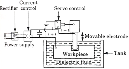
Fig. Electrical discharge machining
- The diagram of electro discharge machining shown in figure.
- EDM is thermal erosion process whereby material is melted and vaporized from an electrically conductive work piece immerse in a liquid dielectric with a series of spark discharge between the tool electrode and the work piece created by a power supply.
- The electrode and the work piece are separated by a dielectric medium.
- The dielectric medium is like as kerosene, paraffin or light oil.
- The strong electrostatic field between the electrode and work piece produce emission of electrons from the cathode.
- In this gap between tool and work piece get ionized. The liquid is force to sparking zone.
- Due to high temperature, the metal at the sparking zone melts instantaneously.
- The material of the tool is usually a material which conduct electricity and which can be easily shaped.
Advantages: -
- Smaller holes can be easy machined.
- No contact between tool and work piece then tool life is increase.
- Any complex shape can be machined.
Disadvantages: -
- Tool life is no longer.
- Power consumption is high.
- Cycle time is more
Surface finish:
The outermost boundary of a body adjacent to the air is called surface. When this surface deformed by a sharp cutting edge, the term surface finish describes the boundary.
A good surface is affected by many variables in single or multiple point machining.
Surface finish is defined in terms of 4 factors:
- Roughness – closely spaced surface irregularities, resulting from the manufacturing process or tools.
- Lay – the overall direction of the roughness pattern which can be affected by the machine and setup.
- Waviness – longer spaced irregularities caused by machine vibration and material warping among other factors.
- Flaws – unique surface imperfections in the material or processing.
Tool wear:
Tool subjected to:
1. Forces
2. Temperature
3. Sliding action
- After continuous use for some time, tool gives unsatisfactory or inefficient performance.
- Unsatisfactory or inefficient performance is due to “Tool Wear or Tool failure”. Consequences:
1. Loss of dimensional accuracy
2. Increased surface roughness
3. Increased power requirement
4. Excessive vibration and abnormal sound (Chatter)
5. Total breakage of the tool
Tool is replaced or reconditioned usually by grinding.
Tool Wear depending factors:
1. Type of tool material and its hardness
2. Type and condition of work piece material
3. Dimensions of cut (Feed and depth of cut)
4. Cutting speed
5. Tool geometry
6. Tool temperature (function of cutting speed, feed and depth of cut)
7. Type of cutting fluid
Classification of Tool Wear
1. Flank wear
2. Crater wear on tool face
3. Localized wear such as the rounding of Cutting edge
4. Chipping of the cutting edge
The main components in EDM:
- Electric power supply
- Dielectric medium
- Work piece & tool
- Servo control unit.
- The work piece and tool are electrically connected to a DC power supply.
- The current density in the discharge of the channel is of the order of 10000 A/cm2 and power density is nearly 500 MW/cm2.
- A gap, known as SPARK GAP in the range, from 0.005 mm to 0.05 mm is maintained between the work piece and the tool.
- Dielectric slurry is forced through this gap at a pressure of 2 kgf/cm2 or lesser.
Working Principle:
- It is a process of metal removal based on the principle of material removal by an interrupted electric spark discharge between the electrode tool and the work piece.
- In EDM, a potential difference is applied between the tool and workpiece.
- Both tool and work material are to be conductors.
- The tool and work material are immersed in a dielectric medium.
- Generally, kerosene or deionized water is used as the dielectric medium.
- A gap is maintained between the tool and the workpiece.
- Depending upon the applied potential difference (50 to 450 V) and the gap between the tool and workpiece, an electric field would be established.
- Generally, the tool is connected to the negative terminal (cathode) of the generator and the workpiece is connected to positive terminal (anode).
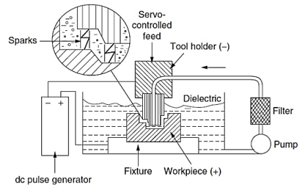
Fig. EDM Schematic
Power & Control Circuits:
Two broad categories of generators (power supplies) are in use on EDM. Commercially available: RC circuits based and transistor-controlled pulses.
In the first category, the main parameters to choose from a setup time are the resistance(s) of the resistor(s) and the capacitance(s) of the capacitor(s).
In an ideal condition, these quantities would affect the maximum current delivered in a discharge.
Current delivery in a discharge is associated with the charge accumulated on the capacitors at a certain moment.
Little control is expected over the time of discharge, which is likely to depend on the actual spark-gap conditions.
Advantage: RC circuit generator can allow the use of short discharge time more easily than the pulse-controlled generator.
Also, the open circuit voltage (i.e., voltage between electrodes when dielectric is not broken) can be identified as steady state voltage of the RC circuit.
In generators based on transistor control, the user is usually able to deliver a train of voltage pulses to the electrodes.
Each pulse can be controlled in shape, for instance, quasi-rectangular.
In particular, the time between two consecutive pulses and the duration of each pulse can be set.
The amplitude of each pulse constitutes the open circuit voltage.
Thus, maximum duration of discharge is equal to duration of a voltage pulse. Maximum current during a discharge that the generator delivers can also be controlled.
Details of generators and control systems on EDMs are not always easily available to their user.
This is a barrier to describing the technological parameters of EDM process. Moreover, the parameters affecting the phenomena occurring between tool and electrode are also related to the motion controller of the electrodes.
A framework to define and measure the electrical parameters during an EDM operation directly on inter-electrode volume with an oscilloscope external to the machine has been recently proposed by Ferri et al.
This would enable the user to estimate directly the electrical parameter that affect their operations without relying upon machine manufacturer's claims.
When machining different materials in the same setup conditions, the actual electrical parameters are significantly different.
When using RC generators, the voltage pulses, shown in Fig. Are responsible for material removal.
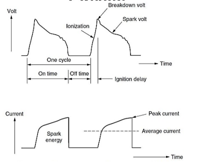
Fig. Voltage and current waveform during EDM
Wire EDM:
- This process is similar to contour cutting with a band saw.
- A slow-moving wire travels along a prescribed path, cutting the work piece with discharge sparks.
- Wire should have sufficient tensile strength and fracture toughness.
- Wire is made of brass, copper or tungsten. (About 0.25mm in diameter).
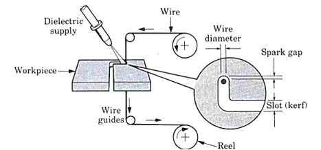
Fig. Wire EDM
- Electrochemical Machining (ECM) is one of the newest and most useful non-traditional machining (NTM) process belonging to Electrochemical category.
- Electrochemical machining (ECM) is used to remove metal and alloys which are difficult or impossible to machine by mechanical machining process.
- The reverse of electroplating.
- This machining process is based Michael Faraday’s classical laws of electrolysis, requiring basically two electrodes, an electrolyte, a gap and a source of D.C power of sufficient capacity.
Working of ECM:
- In the actual process of ECM, the cathode is tool shaped (mirror image of work-piece) and anode is the work-piece.
- A gap (0.05 to 0.7 mm) is provided between the tool and work-piece and electrolyte flows through the gap at a velocity of 30 to 60 m/s and it completes the electrical circuit.
- Electrolyte is pumped at high pressure of 20 kgf/
 (1.96 MPa) through the gap.
 - Electrolyte must be circulated at a rate sufficiently high to conduct current between them and to carry heat.
- Metal is removed from the work-piece by dissolution
- The electric current is of the order of 50 to 40,000 A at 5 to 35 V D.C for current density of 20 to 300 A/
 .
. - Power of 3 KWh is needed to remove 16
 of metal which is almost 30 times the energy required in the conventional process (when the material is readily machinable).
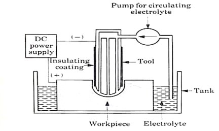
Fig. Electro-chemical machining
Advantages of ECM:
- Process leaves a burr free surface.
- Does not cause any thermal damage to the parts.
- Lack of tool force prevents distortion of parts.
- Capable of machining complex parts and hard materials.
- ECM systems are now available as Numerically Controlled machining centers with capability for high production, high flexibility and high tolerances.
Types of masks used in Chemical machining:
- Cut and peel masks.
- Screen resist masks.
- Photo resist masks.
- Cut and peel maskants:
- Film of chemically resistant material is applied to the work piece by dipping, spraying or flow coating.
- Vinyl, styrene and buta diene are used.
- Rubbery film is then cut & peeled away selectively.
- Manual scribing of mask material usually achieves an accuracy of ±0.13 mm to ±0.75 mm.
2. Screen resist maskants:
- Mask material is applied to the work piece surface by printing, using stencils and a fine polyester or stainless-steel mesh screen.
- Relatively thin coatings with tolerances held to ±0.05 to ±0.18 mm is obtained by screen printing.
- Etching depths are restricted to about 1.5 mm because of thinness of the coating.
3. Photo resist maskants:
- Photo resist mask is quite widely used & is often referred to as photochemical machining.
- Produces intricate & finely detailed shapes using a light activated resist materials.
- WP coated with photo resist material & a master transparency is held against the WP, while exposure to UV rays takes place.
- Light activates the photo resist material in those areas corresponding to opaque parts.
- Tolerances of ±0.025 to 0.005 mm can be produced.
The general requirements of tool material in ECM are:
1. It should be conductor of electricity.
2. It should be rigid enough to take up the load due to fluid pressure.
3. It should be chemically inert to the electrolyte.
4. It should be easily machinable to make it in the desired shape.
Process Parameter:
S.no | Parameters | Values |
1. | Power Supply |
|
| Type | Direct Current |
| Voltage | 2 to 35 V |
| Current | 50 to 40,000 A |
| Current Density | 0.1 A/mm2 to 5 A/mm2 |
2. | Electrolyte |
|
| Material | NaCl and NaNO3 |
| Temperature | 20 oC to 50 oC |
| Flow rate | 20 lpm/100 A current |
| Pressure | 0.5 to 20 bars |
| Dilution | 100 g/l to 500 g/l |
3. | Working gap | 0.1 mm to 2mm |
4. | Overcut | 0.2 mm to 3 mm |
5. | Feed rate | 0.5 mm/min to 15 mm/min |
6. | Electrode material | Copper, brass and bronze |
7. | Surface roughness (Ra) | 0.2 to 1.5 μm |
Material removal rate (MRR):
- Material removal rate (MRR) is an important characteristic to evaluate efficiency of a non-traditional machining process.
- In ECM, material removal takes place due to atomic dissolution of work material which is governed by Faraday’s laws of Electrolysis.
MRR = m / tρ = IA / Fρν
Where m = ItA/Fv = mass of material dissolve
I = current
A = Atomic weight
v = valency
F = Faraday’s constant = 96500 coulombs
ρ = density of the material
Power Supply:
1. Type: direct current
2. Voltage: 2 to 35 V
3. Current: 50 to 40,000 A
4. Current density: 20 A/cm2 to 300 A/cm2
Surface finish is defined in terms of 4 factors:
- Roughness – closely spaced surface irregularities, resulting from the manufacturing process or tools.
- Lay – the overall direction of the roughness pattern which can be affected by the machine and setup.
- Waviness – longer spaced irregularities caused by machine vibration and material warping among other factors.
- Flaws – unique surface imperfections in the material or processing.
References:
1. Kalpakjian and Schmid, Manufacturing processes for engineering materials (5th Edition)-Pearson India, 2014.
2. Mikell P. Groover, Fundamentals of Modern Manufacturing: Materials, Processes, and Systems.
3. Manufacturing Technology by P.N. Rao., MCGRAW HILL INDIA.
4. Materials and Manufacturing by Paul Degarmo.
5. Manufacturing Processes by Kaushish, PHI.
Unit - 6
Electrical Discharge Machining
Unit - 6
Electrical Discharge Machining
Principle of EDM:
Electrical discharge machining (EDM), sometimes also referred to as spark machining, spark eroding, burning, die sinking, wire burning or wire erosion, is a manufacturing process whereby a desired shape is obtained using electrical discharges (sparks).
Material is removed from the work piece by a series of rapidly recurring current discharges between two electrodes, separated by a die-electric liquid and subject to an electric voltage. One of the electrodes is called the tool-electrode, or simply the "tool" or "electrode", while the other is called the workpiece- electrode, or "workpiece".
Working of EDM:
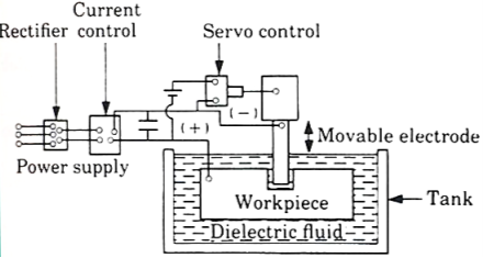
Fig. Electrical discharge machining
- The diagram of electro discharge machining shown in figure.
- EDM is thermal erosion process whereby material is melted and vaporized from an electrically conductive work piece immerse in a liquid dielectric with a series of spark discharge between the tool electrode and the work piece created by a power supply.
- The electrode and the work piece are separated by a dielectric medium.
- The dielectric medium is like as kerosene, paraffin or light oil.
- The strong electrostatic field between the electrode and work piece produce emission of electrons from the cathode.
- In this gap between tool and work piece get ionized. The liquid is force to sparking zone.
- Due to high temperature, the metal at the sparking zone melts instantaneously.
- The material of the tool is usually a material which conduct electricity and which can be easily shaped.
Advantages: -
- Smaller holes can be easy machined.
- No contact between tool and work piece then tool life is increase.
- Any complex shape can be machined.
Disadvantages: -
- Tool life is no longer.
- Power consumption is high.
- Cycle time is more
Surface finish:
The outermost boundary of a body adjacent to the air is called surface. When this surface deformed by a sharp cutting edge, the term surface finish describes the boundary.
A good surface is affected by many variables in single or multiple point machining.
Surface finish is defined in terms of 4 factors:
- Roughness – closely spaced surface irregularities, resulting from the manufacturing process or tools.
- Lay – the overall direction of the roughness pattern which can be affected by the machine and setup.
- Waviness – longer spaced irregularities caused by machine vibration and material warping among other factors.
- Flaws – unique surface imperfections in the material or processing.
Tool wear:
Tool subjected to:
1. Forces
2. Temperature
3. Sliding action
- After continuous use for some time, tool gives unsatisfactory or inefficient performance.
- Unsatisfactory or inefficient performance is due to “Tool Wear or Tool failure”. Consequences:
1. Loss of dimensional accuracy
2. Increased surface roughness
3. Increased power requirement
4. Excessive vibration and abnormal sound (Chatter)
5. Total breakage of the tool
Tool is replaced or reconditioned usually by grinding.
Tool Wear depending factors:
1. Type of tool material and its hardness
2. Type and condition of work piece material
3. Dimensions of cut (Feed and depth of cut)
4. Cutting speed
5. Tool geometry
6. Tool temperature (function of cutting speed, feed and depth of cut)
7. Type of cutting fluid
Classification of Tool Wear
1. Flank wear
2. Crater wear on tool face
3. Localized wear such as the rounding of Cutting edge
4. Chipping of the cutting edge
The main components in EDM:
- Electric power supply
- Dielectric medium
- Work piece & tool
- Servo control unit.
- The work piece and tool are electrically connected to a DC power supply.
- The current density in the discharge of the channel is of the order of 10000 A/cm2 and power density is nearly 500 MW/cm2.
- A gap, known as SPARK GAP in the range, from 0.005 mm to 0.05 mm is maintained between the work piece and the tool.
- Dielectric slurry is forced through this gap at a pressure of 2 kgf/cm2 or lesser.
Working Principle:
- It is a process of metal removal based on the principle of material removal by an interrupted electric spark discharge between the electrode tool and the work piece.
- In EDM, a potential difference is applied between the tool and workpiece.
- Both tool and work material are to be conductors.
- The tool and work material are immersed in a dielectric medium.
- Generally, kerosene or deionized water is used as the dielectric medium.
- A gap is maintained between the tool and the workpiece.
- Depending upon the applied potential difference (50 to 450 V) and the gap between the tool and workpiece, an electric field would be established.
- Generally, the tool is connected to the negative terminal (cathode) of the generator and the workpiece is connected to positive terminal (anode).
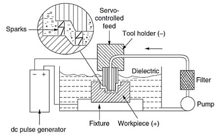
Fig. EDM Schematic
Power & Control Circuits:
Two broad categories of generators (power supplies) are in use on EDM. Commercially available: RC circuits based and transistor-controlled pulses.
In the first category, the main parameters to choose from a setup time are the resistance(s) of the resistor(s) and the capacitance(s) of the capacitor(s).
In an ideal condition, these quantities would affect the maximum current delivered in a discharge.
Current delivery in a discharge is associated with the charge accumulated on the capacitors at a certain moment.
Little control is expected over the time of discharge, which is likely to depend on the actual spark-gap conditions.
Advantage: RC circuit generator can allow the use of short discharge time more easily than the pulse-controlled generator.
Also, the open circuit voltage (i.e., voltage between electrodes when dielectric is not broken) can be identified as steady state voltage of the RC circuit.
In generators based on transistor control, the user is usually able to deliver a train of voltage pulses to the electrodes.
Each pulse can be controlled in shape, for instance, quasi-rectangular.
In particular, the time between two consecutive pulses and the duration of each pulse can be set.
The amplitude of each pulse constitutes the open circuit voltage.
Thus, maximum duration of discharge is equal to duration of a voltage pulse. Maximum current during a discharge that the generator delivers can also be controlled.
Details of generators and control systems on EDMs are not always easily available to their user.
This is a barrier to describing the technological parameters of EDM process. Moreover, the parameters affecting the phenomena occurring between tool and electrode are also related to the motion controller of the electrodes.
A framework to define and measure the electrical parameters during an EDM operation directly on inter-electrode volume with an oscilloscope external to the machine has been recently proposed by Ferri et al.
This would enable the user to estimate directly the electrical parameter that affect their operations without relying upon machine manufacturer's claims.
When machining different materials in the same setup conditions, the actual electrical parameters are significantly different.
When using RC generators, the voltage pulses, shown in Fig. Are responsible for material removal.
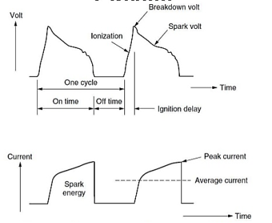
Fig. Voltage and current waveform during EDM
Wire EDM:
- This process is similar to contour cutting with a band saw.
- A slow-moving wire travels along a prescribed path, cutting the work piece with discharge sparks.
- Wire should have sufficient tensile strength and fracture toughness.
- Wire is made of brass, copper or tungsten. (About 0.25mm in diameter).
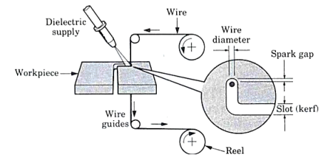
Fig. Wire EDM
Unit - 6
Electrical Discharge Machining
Principle of EDM:
Electrical discharge machining (EDM), sometimes also referred to as spark machining, spark eroding, burning, die sinking, wire burning or wire erosion, is a manufacturing process whereby a desired shape is obtained using electrical discharges (sparks).
Material is removed from the work piece by a series of rapidly recurring current discharges between two electrodes, separated by a die-electric liquid and subject to an electric voltage. One of the electrodes is called the tool-electrode, or simply the "tool" or "electrode", while the other is called the workpiece- electrode, or "workpiece".
Working of EDM:
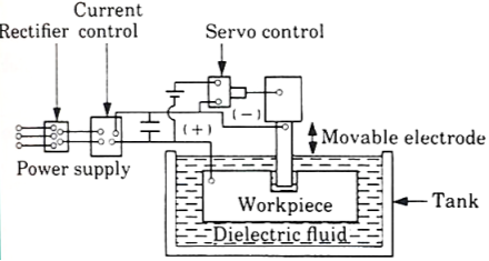
Fig. Electrical discharge machining
- The diagram of electro discharge machining shown in figure.
- EDM is thermal erosion process whereby material is melted and vaporized from an electrically conductive work piece immerse in a liquid dielectric with a series of spark discharge between the tool electrode and the work piece created by a power supply.
- The electrode and the work piece are separated by a dielectric medium.
- The dielectric medium is like as kerosene, paraffin or light oil.
- The strong electrostatic field between the electrode and work piece produce emission of electrons from the cathode.
- In this gap between tool and work piece get ionized. The liquid is force to sparking zone.
- Due to high temperature, the metal at the sparking zone melts instantaneously.
- The material of the tool is usually a material which conduct electricity and which can be easily shaped.
Advantages: -
- Smaller holes can be easy machined.
- No contact between tool and work piece then tool life is increase.
- Any complex shape can be machined.
Disadvantages: -
- Tool life is no longer.
- Power consumption is high.
- Cycle time is more
Surface finish:
The outermost boundary of a body adjacent to the air is called surface. When this surface deformed by a sharp cutting edge, the term surface finish describes the boundary.
A good surface is affected by many variables in single or multiple point machining.
Surface finish is defined in terms of 4 factors:
- Roughness – closely spaced surface irregularities, resulting from the manufacturing process or tools.
- Lay – the overall direction of the roughness pattern which can be affected by the machine and setup.
- Waviness – longer spaced irregularities caused by machine vibration and material warping among other factors.
- Flaws – unique surface imperfections in the material or processing.
Tool wear:
Tool subjected to:
1. Forces
2. Temperature
3. Sliding action
- After continuous use for some time, tool gives unsatisfactory or inefficient performance.
- Unsatisfactory or inefficient performance is due to “Tool Wear or Tool failure”. Consequences:
1. Loss of dimensional accuracy
2. Increased surface roughness
3. Increased power requirement
4. Excessive vibration and abnormal sound (Chatter)
5. Total breakage of the tool
Tool is replaced or reconditioned usually by grinding.
Tool Wear depending factors:
1. Type of tool material and its hardness
2. Type and condition of work piece material
3. Dimensions of cut (Feed and depth of cut)
4. Cutting speed
5. Tool geometry
6. Tool temperature (function of cutting speed, feed and depth of cut)
7. Type of cutting fluid
Classification of Tool Wear
1. Flank wear
2. Crater wear on tool face
3. Localized wear such as the rounding of Cutting edge
4. Chipping of the cutting edge
The main components in EDM:
- Electric power supply
- Dielectric medium
- Work piece & tool
- Servo control unit.
- The work piece and tool are electrically connected to a DC power supply.
- The current density in the discharge of the channel is of the order of 10000 A/cm2 and power density is nearly 500 MW/cm2.
- A gap, known as SPARK GAP in the range, from 0.005 mm to 0.05 mm is maintained between the work piece and the tool.
- Dielectric slurry is forced through this gap at a pressure of 2 kgf/cm2 or lesser.
Working Principle:
- It is a process of metal removal based on the principle of material removal by an interrupted electric spark discharge between the electrode tool and the work piece.
- In EDM, a potential difference is applied between the tool and workpiece.
- Both tool and work material are to be conductors.
- The tool and work material are immersed in a dielectric medium.
- Generally, kerosene or deionized water is used as the dielectric medium.
- A gap is maintained between the tool and the workpiece.
- Depending upon the applied potential difference (50 to 450 V) and the gap between the tool and workpiece, an electric field would be established.
- Generally, the tool is connected to the negative terminal (cathode) of the generator and the workpiece is connected to positive terminal (anode).
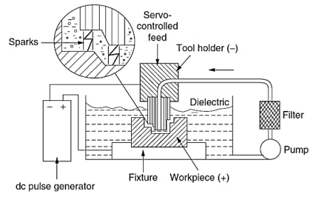
Fig. EDM Schematic
Power & Control Circuits:
Two broad categories of generators (power supplies) are in use on EDM. Commercially available: RC circuits based and transistor-controlled pulses.
In the first category, the main parameters to choose from a setup time are the resistance(s) of the resistor(s) and the capacitance(s) of the capacitor(s).
In an ideal condition, these quantities would affect the maximum current delivered in a discharge.
Current delivery in a discharge is associated with the charge accumulated on the capacitors at a certain moment.
Little control is expected over the time of discharge, which is likely to depend on the actual spark-gap conditions.
Advantage: RC circuit generator can allow the use of short discharge time more easily than the pulse-controlled generator.
Also, the open circuit voltage (i.e., voltage between electrodes when dielectric is not broken) can be identified as steady state voltage of the RC circuit.
In generators based on transistor control, the user is usually able to deliver a train of voltage pulses to the electrodes.
Each pulse can be controlled in shape, for instance, quasi-rectangular.
In particular, the time between two consecutive pulses and the duration of each pulse can be set.
The amplitude of each pulse constitutes the open circuit voltage.
Thus, maximum duration of discharge is equal to duration of a voltage pulse. Maximum current during a discharge that the generator delivers can also be controlled.
Details of generators and control systems on EDMs are not always easily available to their user.
This is a barrier to describing the technological parameters of EDM process. Moreover, the parameters affecting the phenomena occurring between tool and electrode are also related to the motion controller of the electrodes.
A framework to define and measure the electrical parameters during an EDM operation directly on inter-electrode volume with an oscilloscope external to the machine has been recently proposed by Ferri et al.
This would enable the user to estimate directly the electrical parameter that affect their operations without relying upon machine manufacturer's claims.
When machining different materials in the same setup conditions, the actual electrical parameters are significantly different.
When using RC generators, the voltage pulses, shown in Fig. Are responsible for material removal.
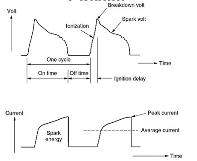
Fig. Voltage and current waveform during EDM
Wire EDM:
- This process is similar to contour cutting with a band saw.
- A slow-moving wire travels along a prescribed path, cutting the work piece with discharge sparks.
- Wire should have sufficient tensile strength and fracture toughness.
- Wire is made of brass, copper or tungsten. (About 0.25mm in diameter).
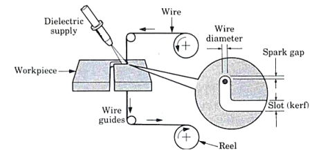
Fig. Wire EDM
- Electrochemical Machining (ECM) is one of the newest and most useful non-traditional machining (NTM) process belonging to Electrochemical category.
- Electrochemical machining (ECM) is used to remove metal and alloys which are difficult or impossible to machine by mechanical machining process.
- The reverse of electroplating.
- This machining process is based Michael Faraday’s classical laws of electrolysis, requiring basically two electrodes, an electrolyte, a gap and a source of D.C power of sufficient capacity.
Working of ECM:
- In the actual process of ECM, the cathode is tool shaped (mirror image of work-piece) and anode is the work-piece.
- A gap (0.05 to 0.7 mm) is provided between the tool and work-piece and electrolyte flows through the gap at a velocity of 30 to 60 m/s and it completes the electrical circuit.
- Electrolyte is pumped at high pressure of 20 kgf/
 (1.96 MPa) through the gap.
 - Electrolyte must be circulated at a rate sufficiently high to conduct current between them and to carry heat.
- Metal is removed from the work-piece by dissolution
- The electric current is of the order of 50 to 40,000 A at 5 to 35 V D.C for current density of 20 to 300 A/
 .
. - Power of 3 KWh is needed to remove 16
 of metal which is almost 30 times the energy required in the conventional process (when the material is readily machinable).
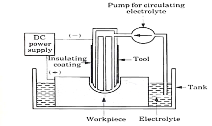
Fig. Electro-chemical machining
Advantages of ECM:
- Process leaves a burr free surface.
- Does not cause any thermal damage to the parts.
- Lack of tool force prevents distortion of parts.
- Capable of machining complex parts and hard materials.
- ECM systems are now available as Numerically Controlled machining centers with capability for high production, high flexibility and high tolerances.
Types of masks used in Chemical machining:
- Cut and peel masks.
- Screen resist masks.
- Photo resist masks.
- Cut and peel maskants:
- Film of chemically resistant material is applied to the work piece by dipping, spraying or flow coating.
- Vinyl, styrene and buta diene are used.
- Rubbery film is then cut & peeled away selectively.
- Manual scribing of mask material usually achieves an accuracy of ±0.13 mm to ±0.75 mm.
2. Screen resist maskants:
- Mask material is applied to the work piece surface by printing, using stencils and a fine polyester or stainless-steel mesh screen.
- Relatively thin coatings with tolerances held to ±0.05 to ±0.18 mm is obtained by screen printing.
- Etching depths are restricted to about 1.5 mm because of thinness of the coating.
3. Photo resist maskants:
- Photo resist mask is quite widely used & is often referred to as photochemical machining.
- Produces intricate & finely detailed shapes using a light activated resist materials.
- WP coated with photo resist material & a master transparency is held against the WP, while exposure to UV rays takes place.
- Light activates the photo resist material in those areas corresponding to opaque parts.
- Tolerances of ±0.025 to 0.005 mm can be produced.
The general requirements of tool material in ECM are:
1. It should be conductor of electricity.
2. It should be rigid enough to take up the load due to fluid pressure.
3. It should be chemically inert to the electrolyte.
4. It should be easily machinable to make it in the desired shape.
Process Parameter:
S.no | Parameters | Values |
1. | Power Supply |
|
| Type | Direct Current |
| Voltage | 2 to 35 V |
| Current | 50 to 40,000 A |
| Current Density | 0.1 A/mm2 to 5 A/mm2 |
2. | Electrolyte |
|
| Material | NaCl and NaNO3 |
| Temperature | 20 oC to 50 oC |
| Flow rate | 20 lpm/100 A current |
| Pressure | 0.5 to 20 bars |
| Dilution | 100 g/l to 500 g/l |
3. | Working gap | 0.1 mm to 2mm |
4. | Overcut | 0.2 mm to 3 mm |
5. | Feed rate | 0.5 mm/min to 15 mm/min |
6. | Electrode material | Copper, brass and bronze |
7. | Surface roughness (Ra) | 0.2 to 1.5 μm |
Material removal rate (MRR):
- Material removal rate (MRR) is an important characteristic to evaluate efficiency of a non-traditional machining process.
- In ECM, material removal takes place due to atomic dissolution of work material which is governed by Faraday’s laws of Electrolysis.
MRR = m / tρ = IA / Fρν
Where m = ItA/Fv = mass of material dissolve
I = current
A = Atomic weight
v = valency
F = Faraday’s constant = 96500 coulombs
ρ = density of the material
Power Supply:
1. Type: direct current
2. Voltage: 2 to 35 V
3. Current: 50 to 40,000 A
4. Current density: 20 A/cm2 to 300 A/cm2
Surface finish is defined in terms of 4 factors:
- Roughness – closely spaced surface irregularities, resulting from the manufacturing process or tools.
- Lay – the overall direction of the roughness pattern which can be affected by the machine and setup.
- Waviness – longer spaced irregularities caused by machine vibration and material warping among other factors.
- Flaws – unique surface imperfections in the material or processing.
References:
1. Kalpakjian and Schmid, Manufacturing processes for engineering materials (5th Edition)-Pearson India, 2014.
2. Mikell P. Groover, Fundamentals of Modern Manufacturing: Materials, Processes, and Systems.
3. Manufacturing Technology by P.N. Rao., MCGRAW HILL INDIA.
4. Materials and Manufacturing by Paul Degarmo.
5. Manufacturing Processes by Kaushish, PHI.