Unit - 7
Laser Beam Machining
Laser-beam machining is a thermal material- removal process that utilizes a high-energy, coherent light beam to melt and vaporize particles on the surface of metallic and non- metallic work pieces.
Lasers can be used to cut, drill, weld and mark. LBM is particularly suitable for making accurately placed holes.
Principle of Laser beam machining (LBM):
- Conversion of electrical energy into heat energy to emit laser beam energy.
- Laser beam is focused on lance then create high energy the high energy concentration on work piece then work piece is melt and vaporized of metal.
Working of LBM
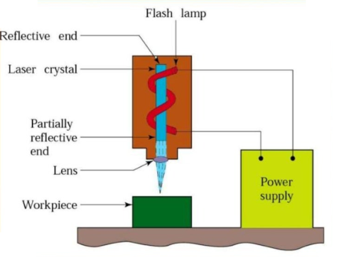
Fig. Laser Beam Machining
- The diagram of LBM is shown in figure.
- Laser is stand for Light Amplification by Simulated Emulsion of Radiation.
- The work piece is placed on the aluminum work table which material is hard not cut by laser beam.
- Ruby rod is used into form of cylindrical crystal both ends of ruby rod are finished to optical tolerance.
- The flash lamp wound around the ruby rod and connected to power supply.
- The ruby rod becomes highly efficient on low temperature and low efficient on high temperature. It is thus continuous cooled with water, air or liquid nitrogen.
- When the light beam has been amplified sufficiently and intensity beam of light comes out form partially reflected end it is focused on the work piece at the focused very high temperature which vaporized and removes the metal on work piece.
Applications: -
- LBM can make very accurate holes as small as 0.005 mm in refractory metals ceramics, and composite material without warping the work pieces.
- It is used for welding of thin metal sheet.
- Leaser can be used for cutting as well as drilling.
- Heat treatment.
- It is used for cutting complex profile.
Limitations: -
- Uneconomic on high volumes compared to stamping.
- Limitations on thickness due to taper.
- High capital cost.
- High maintenance cost.
- Assist or cover gas required
Advantages: -
- Very hard and abrasive material can be cut.
- Sticky materials are also can be cut by this process.
- It is a cost effective and flexible process.
- High accuracy parts can be machined.
- No cutting lubricants required.
- No tool wears.
- Narrow heat effected zone.
- No contact between tool and work piece.
Plasma Arc Machining is used to remove material from the workpiece. In this process, a high velocity jet of high-temperature gas is used to melt and remove material from the workpiece. This high velocity of hot gas is also known as plasma jet.
When a gas or air is heated at a temperature of more than 5000 °C, then it will start getting ionized into positive ions, negative ions and neutral ions. When the gas or air is ionized its temperature reaches from 11000 °C to 28000 °C and this ionized gas is called plasma.
The gas or air is heated with arc and the plasma produced by heating gas is used to remove material from the workpiece. So, the whole process is called Plasma Arc Machining.
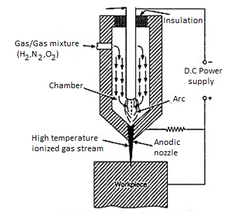
Fig. Plasma Arc Machining
- In this case, the high velocity electrons of are collide with the gas molecules & metal to form ionization of beam.
- The plasma gas is forced through nozzle duct & is made to direct on the work piece to be machined.
- Much of the heating takes place in duct at about 1600 degree Celsius & metal removal is due to electron bombardment & hot plasma.
Mechanism of Metal Removal:
- The metal removal in PAM is due to high temperature of gases.
- The heating of work piece is due to direct electron bombardment plus convective heating of hot plasma.
- The heat produced is sufficient to raise the temperature above its melting point. Approximately 45% of electrical power delivered to torch is used for removal metal from work piece.
- PAM is used for cutting, spraying, & surfacing operations.
Advantages of Plasma arc Machining:
- Rapid Cutting Speeds:
- Plasma arc cutting is faster than oxyfuel for cutting steel up to 50 mm thick and is competitive for greater thickness.
- Plasma cutting achieves speeds greater than those of laser cutting systems for thickness over 3 mm.
- The fast-cutting speeds result in increased production, enabling systems to pay for themselves in as little as 6 months for smaller units.
2. Wide Range of Materials and Thickness:
- Plasma cutting systems can yield quality cuts on both ferrous and nonferrous metals. Thickness from gauge to 80 mm can be cut effectively.
3. Easy to Use:
- Plasma cutting requires only minimal operator training. The torch is easy to operate, and new operators can make excellent cuts almost immediately. Plasma cutting systems are rugged, are well suitable for production environments, and do not require the potentially complicated adjustments associated with laser cutting systems.
4. Economical:
- Plasma cutting is more economical than oxyfuel for thickness under 25 mm, and comparable up to about 50 mm. For example, for 12 mm steel, plasma cutting costs are about half those of oxyfuel.
Disadvantages of Plasma Arc Machining:
- The cutter's electrode and nozzle sometimes require frequent replacement which adds to the cost of operation.
- Non-conductive materials such as wood or plastic cannot be cut with plasma cutters with transferred arc type.
- Another minor drawback is that the plasma arc typically leaves a 4–6-degree bevel on the cut edge, although this angle is almost invisible on thinner material, it is noticeable on thicker pieces.
- Electron Beam Machining (EBM) is a thermal process. Here a steam of high-speed electrons impinges on the work surface so that the kinetic energy of electrons is transferred to work producing intense heating.
- Depending upon the intensity of heating the work piece can melt and vaporize.
- The process of heating by electron beam is used for annealing, welding or metal removal.
- During EBM process very high velocities can be obtained by using enough voltage of 1,50,000 V can produce velocity of 228,478 km/sec and it is focused on 10 – 200 μM diameter.
- Power density can go up to 6500 billion W/sq.mm. Such a power density can vaporize any substance immediately.
- Complex contours can be easily machined by maneuvering the electron beam using magnetic deflection coils
- To avoid a collision of the accelerating electrons with the air molecules, the process has to be conducted in vacuum. So, EBM is not suitable for large work pieces.
- Process is accomplished with vacuum so no possibility of contamination.
- No effects on work piece because about 25- 50μm away from machining spot remains at room temperature and so no effects of high temperature on work
Working of EBM
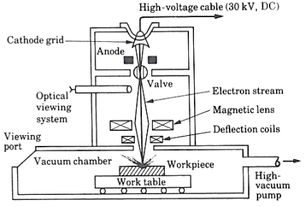
Fig. Electron Beam Machining
- The EBM beam is operated in pulse mode.
- This is achieved by appropriately biasing the biased grid located just after the cathode.
- Switching pulses are given to the bias grid so as to achieve pulse duration of as low as 50 μs to as long as 15 ms.
- Beam current is directly related to the number of electrons emitted by the cathode or available in the beam.
- Beam current once again can be as low as 200μ amp to 1 amp. Increasing the beam current directly increases the energy per pulse.
- Similarly increase in pulse duration also enhances energy per pulse.
- High-energy pulses (in excess of 100 J/pulse) can machine larger holes on thicker plates.
- A higher energy density, i.e., for a lower spot size, the material removal would be faster though the size of the hole would be smaller.
- The plane of focusing would be on the surface of the work piece or just below the surface of the work piece.
Applications: -
- Used for producing very small size holes like holes in diesel injection nozzles, Air brakes etc.
- Used only for circular holes.
Limitations: -
- Material removal rate is very low compared to other convectional machining processes.
- Maintaining perfect vacuum is very difficult.
- The machining process can’t be seen by operator.
- Work piece material should be electrically conducting.
Advantages: -
- Very small size holes can be produced.
- Surface finish produced is good.
- Highly reactive metals like Al and Mg can be machined very easily.
References:
1. Kalpakjian and Schmid, Manufacturing processes for engineering materials (5th Edition)-Pearson India, 2014.
2. Mikell P. Groover, Fundamentals of Modern Manufacturing: Materials, Processes, and Systems.
3. Manufacturing Technology by P.N. Rao., MCGRAW HILL INDIA.
4. Materials and Manufacturing by Paul Degarmo.
5. Manufacturing Processes by Kaushish, PHI.
Unit - 7
Laser Beam Machining
Laser-beam machining is a thermal material- removal process that utilizes a high-energy, coherent light beam to melt and vaporize particles on the surface of metallic and non- metallic work pieces.
Lasers can be used to cut, drill, weld and mark. LBM is particularly suitable for making accurately placed holes.
Principle of Laser beam machining (LBM):
- Conversion of electrical energy into heat energy to emit laser beam energy.
- Laser beam is focused on lance then create high energy the high energy concentration on work piece then work piece is melt and vaporized of metal.
Working of LBM
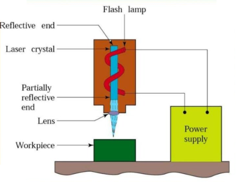
Fig. Laser Beam Machining
- The diagram of LBM is shown in figure.
- Laser is stand for Light Amplification by Simulated Emulsion of Radiation.
- The work piece is placed on the aluminum work table which material is hard not cut by laser beam.
- Ruby rod is used into form of cylindrical crystal both ends of ruby rod are finished to optical tolerance.
- The flash lamp wound around the ruby rod and connected to power supply.
- The ruby rod becomes highly efficient on low temperature and low efficient on high temperature. It is thus continuous cooled with water, air or liquid nitrogen.
- When the light beam has been amplified sufficiently and intensity beam of light comes out form partially reflected end it is focused on the work piece at the focused very high temperature which vaporized and removes the metal on work piece.
Applications: -
- LBM can make very accurate holes as small as 0.005 mm in refractory metals ceramics, and composite material without warping the work pieces.
- It is used for welding of thin metal sheet.
- Leaser can be used for cutting as well as drilling.
- Heat treatment.
- It is used for cutting complex profile.
Limitations: -
- Uneconomic on high volumes compared to stamping.
- Limitations on thickness due to taper.
- High capital cost.
- High maintenance cost.
- Assist or cover gas required
Advantages: -
- Very hard and abrasive material can be cut.
- Sticky materials are also can be cut by this process.
- It is a cost effective and flexible process.
- High accuracy parts can be machined.
- No cutting lubricants required.
- No tool wears.
- Narrow heat effected zone.
- No contact between tool and work piece.
Plasma Arc Machining is used to remove material from the workpiece. In this process, a high velocity jet of high-temperature gas is used to melt and remove material from the workpiece. This high velocity of hot gas is also known as plasma jet.
When a gas or air is heated at a temperature of more than 5000 °C, then it will start getting ionized into positive ions, negative ions and neutral ions. When the gas or air is ionized its temperature reaches from 11000 °C to 28000 °C and this ionized gas is called plasma.
The gas or air is heated with arc and the plasma produced by heating gas is used to remove material from the workpiece. So, the whole process is called Plasma Arc Machining.
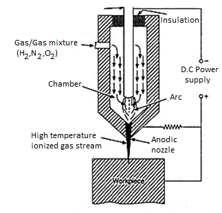
Fig. Plasma Arc Machining
- In this case, the high velocity electrons of are collide with the gas molecules & metal to form ionization of beam.
- The plasma gas is forced through nozzle duct & is made to direct on the work piece to be machined.
- Much of the heating takes place in duct at about 1600 degree Celsius & metal removal is due to electron bombardment & hot plasma.
Mechanism of Metal Removal:
- The metal removal in PAM is due to high temperature of gases.
- The heating of work piece is due to direct electron bombardment plus convective heating of hot plasma.
- The heat produced is sufficient to raise the temperature above its melting point. Approximately 45% of electrical power delivered to torch is used for removal metal from work piece.
- PAM is used for cutting, spraying, & surfacing operations.
Advantages of Plasma arc Machining:
- Rapid Cutting Speeds:
- Plasma arc cutting is faster than oxyfuel for cutting steel up to 50 mm thick and is competitive for greater thickness.
- Plasma cutting achieves speeds greater than those of laser cutting systems for thickness over 3 mm.
- The fast-cutting speeds result in increased production, enabling systems to pay for themselves in as little as 6 months for smaller units.
2. Wide Range of Materials and Thickness:
- Plasma cutting systems can yield quality cuts on both ferrous and nonferrous metals. Thickness from gauge to 80 mm can be cut effectively.
3. Easy to Use:
- Plasma cutting requires only minimal operator training. The torch is easy to operate, and new operators can make excellent cuts almost immediately. Plasma cutting systems are rugged, are well suitable for production environments, and do not require the potentially complicated adjustments associated with laser cutting systems.
4. Economical:
- Plasma cutting is more economical than oxyfuel for thickness under 25 mm, and comparable up to about 50 mm. For example, for 12 mm steel, plasma cutting costs are about half those of oxyfuel.
Disadvantages of Plasma Arc Machining:
- The cutter's electrode and nozzle sometimes require frequent replacement which adds to the cost of operation.
- Non-conductive materials such as wood or plastic cannot be cut with plasma cutters with transferred arc type.
- Another minor drawback is that the plasma arc typically leaves a 4–6-degree bevel on the cut edge, although this angle is almost invisible on thinner material, it is noticeable on thicker pieces.
- Electron Beam Machining (EBM) is a thermal process. Here a steam of high-speed electrons impinges on the work surface so that the kinetic energy of electrons is transferred to work producing intense heating.
- Depending upon the intensity of heating the work piece can melt and vaporize.
- The process of heating by electron beam is used for annealing, welding or metal removal.
- During EBM process very high velocities can be obtained by using enough voltage of 1,50,000 V can produce velocity of 228,478 km/sec and it is focused on 10 – 200 μM diameter.
- Power density can go up to 6500 billion W/sq.mm. Such a power density can vaporize any substance immediately.
- Complex contours can be easily machined by maneuvering the electron beam using magnetic deflection coils
- To avoid a collision of the accelerating electrons with the air molecules, the process has to be conducted in vacuum. So, EBM is not suitable for large work pieces.
- Process is accomplished with vacuum so no possibility of contamination.
- No effects on work piece because about 25- 50μm away from machining spot remains at room temperature and so no effects of high temperature on work
Working of EBM
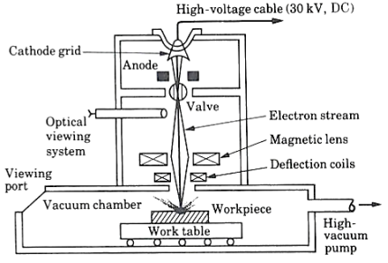
Fig. Electron Beam Machining
- The EBM beam is operated in pulse mode.
- This is achieved by appropriately biasing the biased grid located just after the cathode.
- Switching pulses are given to the bias grid so as to achieve pulse duration of as low as 50 μs to as long as 15 ms.
- Beam current is directly related to the number of electrons emitted by the cathode or available in the beam.
- Beam current once again can be as low as 200μ amp to 1 amp. Increasing the beam current directly increases the energy per pulse.
- Similarly increase in pulse duration also enhances energy per pulse.
- High-energy pulses (in excess of 100 J/pulse) can machine larger holes on thicker plates.
- A higher energy density, i.e., for a lower spot size, the material removal would be faster though the size of the hole would be smaller.
- The plane of focusing would be on the surface of the work piece or just below the surface of the work piece.
Applications: -
- Used for producing very small size holes like holes in diesel injection nozzles, Air brakes etc.
- Used only for circular holes.
Limitations: -
- Material removal rate is very low compared to other convectional machining processes.
- Maintaining perfect vacuum is very difficult.
- The machining process can’t be seen by operator.
- Work piece material should be electrically conducting.
Advantages: -
- Very small size holes can be produced.
- Surface finish produced is good.
- Highly reactive metals like Al and Mg can be machined very easily.
References:
1. Kalpakjian and Schmid, Manufacturing processes for engineering materials (5th Edition)-Pearson India, 2014.
2. Mikell P. Groover, Fundamentals of Modern Manufacturing: Materials, Processes, and Systems.
3. Manufacturing Technology by P.N. Rao., MCGRAW HILL INDIA.
4. Materials and Manufacturing by Paul Degarmo.
5. Manufacturing Processes by Kaushish, PHI.
Unit - 7
Laser Beam Machining
Unit - 7
Laser Beam Machining
Laser-beam machining is a thermal material- removal process that utilizes a high-energy, coherent light beam to melt and vaporize particles on the surface of metallic and non- metallic work pieces.
Lasers can be used to cut, drill, weld and mark. LBM is particularly suitable for making accurately placed holes.
Principle of Laser beam machining (LBM):
- Conversion of electrical energy into heat energy to emit laser beam energy.
- Laser beam is focused on lance then create high energy the high energy concentration on work piece then work piece is melt and vaporized of metal.
Working of LBM
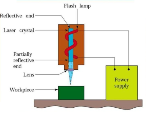
Fig. Laser Beam Machining
- The diagram of LBM is shown in figure.
- Laser is stand for Light Amplification by Simulated Emulsion of Radiation.
- The work piece is placed on the aluminum work table which material is hard not cut by laser beam.
- Ruby rod is used into form of cylindrical crystal both ends of ruby rod are finished to optical tolerance.
- The flash lamp wound around the ruby rod and connected to power supply.
- The ruby rod becomes highly efficient on low temperature and low efficient on high temperature. It is thus continuous cooled with water, air or liquid nitrogen.
- When the light beam has been amplified sufficiently and intensity beam of light comes out form partially reflected end it is focused on the work piece at the focused very high temperature which vaporized and removes the metal on work piece.
Applications: -
- LBM can make very accurate holes as small as 0.005 mm in refractory metals ceramics, and composite material without warping the work pieces.
- It is used for welding of thin metal sheet.
- Leaser can be used for cutting as well as drilling.
- Heat treatment.
- It is used for cutting complex profile.
Limitations: -
- Uneconomic on high volumes compared to stamping.
- Limitations on thickness due to taper.
- High capital cost.
- High maintenance cost.
- Assist or cover gas required
Advantages: -
- Very hard and abrasive material can be cut.
- Sticky materials are also can be cut by this process.
- It is a cost effective and flexible process.
- High accuracy parts can be machined.
- No cutting lubricants required.
- No tool wears.
- Narrow heat effected zone.
- No contact between tool and work piece.
Plasma Arc Machining is used to remove material from the workpiece. In this process, a high velocity jet of high-temperature gas is used to melt and remove material from the workpiece. This high velocity of hot gas is also known as plasma jet.
When a gas or air is heated at a temperature of more than 5000 °C, then it will start getting ionized into positive ions, negative ions and neutral ions. When the gas or air is ionized its temperature reaches from 11000 °C to 28000 °C and this ionized gas is called plasma.
The gas or air is heated with arc and the plasma produced by heating gas is used to remove material from the workpiece. So, the whole process is called Plasma Arc Machining.
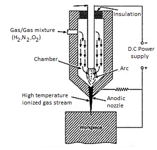
Fig. Plasma Arc Machining
- In this case, the high velocity electrons of are collide with the gas molecules & metal to form ionization of beam.
- The plasma gas is forced through nozzle duct & is made to direct on the work piece to be machined.
- Much of the heating takes place in duct at about 1600 degree Celsius & metal removal is due to electron bombardment & hot plasma.
Mechanism of Metal Removal:
- The metal removal in PAM is due to high temperature of gases.
- The heating of work piece is due to direct electron bombardment plus convective heating of hot plasma.
- The heat produced is sufficient to raise the temperature above its melting point. Approximately 45% of electrical power delivered to torch is used for removal metal from work piece.
- PAM is used for cutting, spraying, & surfacing operations.
Advantages of Plasma arc Machining:
- Rapid Cutting Speeds:
- Plasma arc cutting is faster than oxyfuel for cutting steel up to 50 mm thick and is competitive for greater thickness.
- Plasma cutting achieves speeds greater than those of laser cutting systems for thickness over 3 mm.
- The fast-cutting speeds result in increased production, enabling systems to pay for themselves in as little as 6 months for smaller units.
2. Wide Range of Materials and Thickness:
- Plasma cutting systems can yield quality cuts on both ferrous and nonferrous metals. Thickness from gauge to 80 mm can be cut effectively.
3. Easy to Use:
- Plasma cutting requires only minimal operator training. The torch is easy to operate, and new operators can make excellent cuts almost immediately. Plasma cutting systems are rugged, are well suitable for production environments, and do not require the potentially complicated adjustments associated with laser cutting systems.
4. Economical:
- Plasma cutting is more economical than oxyfuel for thickness under 25 mm, and comparable up to about 50 mm. For example, for 12 mm steel, plasma cutting costs are about half those of oxyfuel.
Disadvantages of Plasma Arc Machining:
- The cutter's electrode and nozzle sometimes require frequent replacement which adds to the cost of operation.
- Non-conductive materials such as wood or plastic cannot be cut with plasma cutters with transferred arc type.
- Another minor drawback is that the plasma arc typically leaves a 4–6-degree bevel on the cut edge, although this angle is almost invisible on thinner material, it is noticeable on thicker pieces.
- Electron Beam Machining (EBM) is a thermal process. Here a steam of high-speed electrons impinges on the work surface so that the kinetic energy of electrons is transferred to work producing intense heating.
- Depending upon the intensity of heating the work piece can melt and vaporize.
- The process of heating by electron beam is used for annealing, welding or metal removal.
- During EBM process very high velocities can be obtained by using enough voltage of 1,50,000 V can produce velocity of 228,478 km/sec and it is focused on 10 – 200 μM diameter.
- Power density can go up to 6500 billion W/sq.mm. Such a power density can vaporize any substance immediately.
- Complex contours can be easily machined by maneuvering the electron beam using magnetic deflection coils
- To avoid a collision of the accelerating electrons with the air molecules, the process has to be conducted in vacuum. So, EBM is not suitable for large work pieces.
- Process is accomplished with vacuum so no possibility of contamination.
- No effects on work piece because about 25- 50μm away from machining spot remains at room temperature and so no effects of high temperature on work
Working of EBM
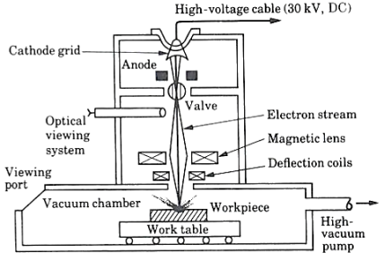
Fig. Electron Beam Machining
- The EBM beam is operated in pulse mode.
- This is achieved by appropriately biasing the biased grid located just after the cathode.
- Switching pulses are given to the bias grid so as to achieve pulse duration of as low as 50 μs to as long as 15 ms.
- Beam current is directly related to the number of electrons emitted by the cathode or available in the beam.
- Beam current once again can be as low as 200μ amp to 1 amp. Increasing the beam current directly increases the energy per pulse.
- Similarly increase in pulse duration also enhances energy per pulse.
- High-energy pulses (in excess of 100 J/pulse) can machine larger holes on thicker plates.
- A higher energy density, i.e., for a lower spot size, the material removal would be faster though the size of the hole would be smaller.
- The plane of focusing would be on the surface of the work piece or just below the surface of the work piece.
Applications: -
- Used for producing very small size holes like holes in diesel injection nozzles, Air brakes etc.
- Used only for circular holes.
Limitations: -
- Material removal rate is very low compared to other convectional machining processes.
- Maintaining perfect vacuum is very difficult.
- The machining process can’t be seen by operator.
- Work piece material should be electrically conducting.
Advantages: -
- Very small size holes can be produced.
- Surface finish produced is good.
- Highly reactive metals like Al and Mg can be machined very easily.
References:
1. Kalpakjian and Schmid, Manufacturing processes for engineering materials (5th Edition)-Pearson India, 2014.
2. Mikell P. Groover, Fundamentals of Modern Manufacturing: Materials, Processes, and Systems.
3. Manufacturing Technology by P.N. Rao., MCGRAW HILL INDIA.
4. Materials and Manufacturing by Paul Degarmo.
5. Manufacturing Processes by Kaushish, PHI.
Unit - 7
Laser Beam Machining
Laser-beam machining is a thermal material- removal process that utilizes a high-energy, coherent light beam to melt and vaporize particles on the surface of metallic and non- metallic work pieces.
Lasers can be used to cut, drill, weld and mark. LBM is particularly suitable for making accurately placed holes.
Principle of Laser beam machining (LBM):
- Conversion of electrical energy into heat energy to emit laser beam energy.
- Laser beam is focused on lance then create high energy the high energy concentration on work piece then work piece is melt and vaporized of metal.
Working of LBM
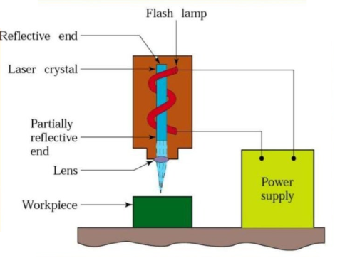
Fig. Laser Beam Machining
- The diagram of LBM is shown in figure.
- Laser is stand for Light Amplification by Simulated Emulsion of Radiation.
- The work piece is placed on the aluminum work table which material is hard not cut by laser beam.
- Ruby rod is used into form of cylindrical crystal both ends of ruby rod are finished to optical tolerance.
- The flash lamp wound around the ruby rod and connected to power supply.
- The ruby rod becomes highly efficient on low temperature and low efficient on high temperature. It is thus continuous cooled with water, air or liquid nitrogen.
- When the light beam has been amplified sufficiently and intensity beam of light comes out form partially reflected end it is focused on the work piece at the focused very high temperature which vaporized and removes the metal on work piece.
Applications: -
- LBM can make very accurate holes as small as 0.005 mm in refractory metals ceramics, and composite material without warping the work pieces.
- It is used for welding of thin metal sheet.
- Leaser can be used for cutting as well as drilling.
- Heat treatment.
- It is used for cutting complex profile.
Limitations: -
- Uneconomic on high volumes compared to stamping.
- Limitations on thickness due to taper.
- High capital cost.
- High maintenance cost.
- Assist or cover gas required
Advantages: -
- Very hard and abrasive material can be cut.
- Sticky materials are also can be cut by this process.
- It is a cost effective and flexible process.
- High accuracy parts can be machined.
- No cutting lubricants required.
- No tool wears.
- Narrow heat effected zone.
- No contact between tool and work piece.
Plasma Arc Machining is used to remove material from the workpiece. In this process, a high velocity jet of high-temperature gas is used to melt and remove material from the workpiece. This high velocity of hot gas is also known as plasma jet.
When a gas or air is heated at a temperature of more than 5000 °C, then it will start getting ionized into positive ions, negative ions and neutral ions. When the gas or air is ionized its temperature reaches from 11000 °C to 28000 °C and this ionized gas is called plasma.
The gas or air is heated with arc and the plasma produced by heating gas is used to remove material from the workpiece. So, the whole process is called Plasma Arc Machining.
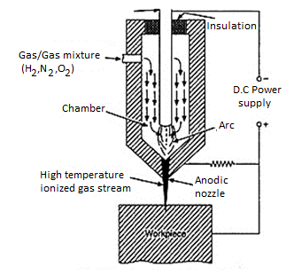
Fig. Plasma Arc Machining
- In this case, the high velocity electrons of are collide with the gas molecules & metal to form ionization of beam.
- The plasma gas is forced through nozzle duct & is made to direct on the work piece to be machined.
- Much of the heating takes place in duct at about 1600 degree Celsius & metal removal is due to electron bombardment & hot plasma.
Mechanism of Metal Removal:
- The metal removal in PAM is due to high temperature of gases.
- The heating of work piece is due to direct electron bombardment plus convective heating of hot plasma.
- The heat produced is sufficient to raise the temperature above its melting point. Approximately 45% of electrical power delivered to torch is used for removal metal from work piece.
- PAM is used for cutting, spraying, & surfacing operations.
Advantages of Plasma arc Machining:
- Rapid Cutting Speeds:
- Plasma arc cutting is faster than oxyfuel for cutting steel up to 50 mm thick and is competitive for greater thickness.
- Plasma cutting achieves speeds greater than those of laser cutting systems for thickness over 3 mm.
- The fast-cutting speeds result in increased production, enabling systems to pay for themselves in as little as 6 months for smaller units.
2. Wide Range of Materials and Thickness:
- Plasma cutting systems can yield quality cuts on both ferrous and nonferrous metals. Thickness from gauge to 80 mm can be cut effectively.
3. Easy to Use:
- Plasma cutting requires only minimal operator training. The torch is easy to operate, and new operators can make excellent cuts almost immediately. Plasma cutting systems are rugged, are well suitable for production environments, and do not require the potentially complicated adjustments associated with laser cutting systems.
4. Economical:
- Plasma cutting is more economical than oxyfuel for thickness under 25 mm, and comparable up to about 50 mm. For example, for 12 mm steel, plasma cutting costs are about half those of oxyfuel.
Disadvantages of Plasma Arc Machining:
- The cutter's electrode and nozzle sometimes require frequent replacement which adds to the cost of operation.
- Non-conductive materials such as wood or plastic cannot be cut with plasma cutters with transferred arc type.
- Another minor drawback is that the plasma arc typically leaves a 4–6-degree bevel on the cut edge, although this angle is almost invisible on thinner material, it is noticeable on thicker pieces.
- Electron Beam Machining (EBM) is a thermal process. Here a steam of high-speed electrons impinges on the work surface so that the kinetic energy of electrons is transferred to work producing intense heating.
- Depending upon the intensity of heating the work piece can melt and vaporize.
- The process of heating by electron beam is used for annealing, welding or metal removal.
- During EBM process very high velocities can be obtained by using enough voltage of 1,50,000 V can produce velocity of 228,478 km/sec and it is focused on 10 – 200 μM diameter.
- Power density can go up to 6500 billion W/sq.mm. Such a power density can vaporize any substance immediately.
- Complex contours can be easily machined by maneuvering the electron beam using magnetic deflection coils
- To avoid a collision of the accelerating electrons with the air molecules, the process has to be conducted in vacuum. So, EBM is not suitable for large work pieces.
- Process is accomplished with vacuum so no possibility of contamination.
- No effects on work piece because about 25- 50μm away from machining spot remains at room temperature and so no effects of high temperature on work
Working of EBM
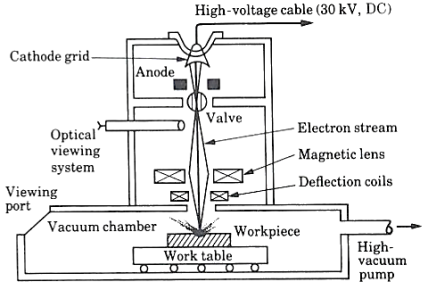
Fig. Electron Beam Machining
- The EBM beam is operated in pulse mode.
- This is achieved by appropriately biasing the biased grid located just after the cathode.
- Switching pulses are given to the bias grid so as to achieve pulse duration of as low as 50 μs to as long as 15 ms.
- Beam current is directly related to the number of electrons emitted by the cathode or available in the beam.
- Beam current once again can be as low as 200μ amp to 1 amp. Increasing the beam current directly increases the energy per pulse.
- Similarly increase in pulse duration also enhances energy per pulse.
- High-energy pulses (in excess of 100 J/pulse) can machine larger holes on thicker plates.
- A higher energy density, i.e., for a lower spot size, the material removal would be faster though the size of the hole would be smaller.
- The plane of focusing would be on the surface of the work piece or just below the surface of the work piece.
Applications: -
- Used for producing very small size holes like holes in diesel injection nozzles, Air brakes etc.
- Used only for circular holes.
Limitations: -
- Material removal rate is very low compared to other convectional machining processes.
- Maintaining perfect vacuum is very difficult.
- The machining process can’t be seen by operator.
- Work piece material should be electrically conducting.
Advantages: -
- Very small size holes can be produced.
- Surface finish produced is good.
- Highly reactive metals like Al and Mg can be machined very easily.
References:
1. Kalpakjian and Schmid, Manufacturing processes for engineering materials (5th Edition)-Pearson India, 2014.
2. Mikell P. Groover, Fundamentals of Modern Manufacturing: Materials, Processes, and Systems.
3. Manufacturing Technology by P.N. Rao., MCGRAW HILL INDIA.
4. Materials and Manufacturing by Paul Degarmo.
5. Manufacturing Processes by Kaushish, PHI.