Unit - 1
Classification of mechanisms
A mechanism is defined as the assembly of bodies in such a way that motion in one body causes constrained and predictable motion in other bodies. Or we can say a mechanism is a combination of several bodies to produce a specified motion Mechanisms can be classified in following four types:
Classification of Mechanisms
The mechanisms are of the following types:
1. On the basis of number of links
a. Simple mechanism: A mechanism which has four links.
b. Compound mechanism: A mechanism which has more than four links.
2. On the basis of number of pairs
a. Mechanism having three pairs.
b. Mechanism having 4 pairs.
c. Mechanism having more than 4 pairs.
3. On the basis of motion of particles
a. Planar mechanism: When all the links of the mechanism lie in the same plane.
b. Spatial mechanism: When the links of the mechanism lie in different planes.
Kinematics
Kinematics is the branch of mechanics in which the motion of a particle is studied without consideration of forces. Kinematics of machines deals with the study of the relative motion of machine parts. It involves the study of position, displacement, velocity and acceleration of machine parts.
Kinematic link (or) element
Kinematic link or element is the basic or smallest unit of a mechanism. Generally kinematic links are assumed to be rigid during analysis of kinematic performance of a machine. These links can be classified in following two categories:
Based on number of elements of link | Based on type of structural behavior |
Binary link: Link which is connected to other links at two points.  | Rigid link. A rigid link is the one which does not deform during the transmission of the motion. e.g. Connecting rod, crank etc. |
Ternary link: Link which is connected to other links at three points.  | Flexible link. A flexible link can deform partly during transmission of motion without affecting the transmission. e.g.-belts, ropes, chains and wires. |
Quaternary link: Link which is connected to other links at four points.  | Fluid link. A link in which transmission of motion takes place through the fluid pressure. e.g.- hydraulic presses, jacks and brakes. |
Kinematic pair
Connection between two links is known as a kinematic pair when the relative motion between them is a constrained motion.
Classification of kinematic pair
The kinematic pairs may be classified according to the following considerations:
- On the basis of relative motion
- On the basis of contact
- On the basis of mechanical constraint.
Based on relative motion between pairing elements:
Name of kinematic pair | Description | Diagram |
Siding pair | Two elements so connected that one element slides over or inside the other. DOF =1 |  |
Turning/Revolute pair | Connection between two elements in such a way that one element rotates with respect to another. DOF =1 |  |
Cylindrical pair | Relative motion between the pairing elements is the combination of turning and sliding, DOF =2 | 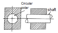 |
Rolling pair
| Contact between the pair elements is rolling. DOF = 1 | 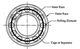 |
Spherical pair |
When one element in the form of a sphere turns about the other fixed element, it forms a spherical pair. DOF = 3 |  |
Helical/screw pair | In this kind of pair one element turns about the other element through the screw threads present in it. DOF = 1 |  |
Based on nature of contact between elements:
Name of kinematic pair | Description | Diagram |
Lower pair | If the joint by which two members are connected has surface contact, the pair is known as a lower pair. |  |
Higher pair | If the contact between the pairing elements takes place at a point or along a line, it is known as a higher pair. | 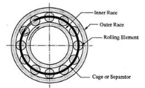 |
|
|
|
Based on the nature of mechanical constraint:
Name of kinematic pair | Description | Diagram |
Closed pair | Elements of pairs held together mechanically due to their geometry constitute a closed pair. |  |
Unclosed/force closed pair | Elements of pairs held together by the action of external forces constitute unclosed or force closed pairs. | 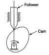 |
Degrees of freedom/mobility of a mechanism:
Degrees of freedom of a kinematic pair is defined as the number of independent relative motions, both translational and rotational, a kinematic pair can have.
Degrees of freedom = 6- number of restraints
Kutzbach criterion:
The Kutzbach criterion for determining the number of degrees of freedom of a planar mechanism is:
F=3n-1-2p-h
Where, F = number of degree of freedom for mechanism
n = number of links
p = number of joints having single degree of freedom
h = number of joints with 2 degrees of freedom.
Kinematic chain
A kinematic chain may be defined as an assembly of links in which the relative motion of the links is possible and the motion of each relative to the others is definite. The last link of the kinematic chain is attached to the first link. e.g. Four bar chain and slider crank mechanism.
The Four Bar Chain Mechanism
It is the most fundamental mechanism, which consists of four binary links interconnected by four pin joints in the form of a quadrilateral. In a four-bar chain mechanism link that makes complete revolutions is the crank, the link opposite to the fixed link is the coupler, and the fourth link a lever or rocker, if it oscillates or another crank, if it rotates shown in Figure 1.
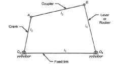
Figure 1. Four bar chain mechanism and its components
This law states that a four-bar chain mechanism has at least one revolving pair if the sum of length of smallest and largest links is less than sum of length of other two links.
(l+s)≤(p+q)
Where, l = length of largest link
s = length of smallest link
p and q = lengths of other two links.
Mechanisms that follow the above criteria are also known as class I mechanism. If (l+s)>(p+q) The mechanism is known as class II mechanism. In which every inversion of a four-bar chain results in a rocker-rocker mechanism.
Kinematic inversion is the different kinds of mechanisms by fixing different links of a mechanism. Kinematic inversions of four-bar chain mechanism are:
Double crank mechanism
If the smallest link of the four bar chain is fixed the resulting mechanism is a double crank mechanism. In this mechanism both input and output links make complete revolution.
Crank-rocker mechanism
If any link adjacent to the smallest link is fixed, a crank-rocker mechanism is obtained. In this mechanism one link makes complete revolution while one link oscillates.
Double crank mechanism
This inversion of a four-bar chain mechanism is obtained when the link opposite to the smallest link is fixed. In this case both input and output links oscillate.
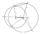
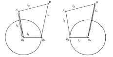
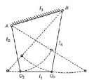
(a)(b)(c)
Figure 2. Inversions of four-bar chain mechanism (a) double crank (b) crank-rocker mechanism (c) double rocker mechanism.
Some practical applications of four bar chain mechanism
Inversion | Application | Diagram |
Double crank | Locomotive wheel |  |
Crank rocker | Beam engine | 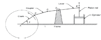 |
Double rocker | Watt indicator |  |
Slider-crank mechanism
When one of the turning pairs of a four-bar chain is replaced by a sliding pair, it becomes a single slider-crank chain mechanism. In Figure 3 links 1-2, 2-3 and 3-4 form turning pairs while links 4-1 form a sliding pair.
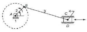
Figure 3. Slider crank mechanism
Inversions of slider crank chain
Slider crank mechanism has following four inversions:
Inversion | Description and Application | Diagram |
First inversion | Link 1 is Fixed. Link 2 and 4 are crank and slider. Application: Reciprocating engine and reciprocating pump etc. | 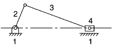 |
Second inversion | If we fix the crank of the previous mechanism, link 1 and 3 can complete the revolution and slider slides on link 1. Application: Whitworth quick-return mechanism and Rotary engine. | 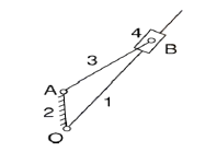 |
Third inversion | This inversion is obtained by fixing the 3rd link, in this case link 2 rotates while link 4 oscillates. Application: Oscillating cylinder engine and crank and slotted lever mechanism. | 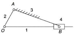 |
Fourth inversion | If we fix the 4th link of the slider crank mechanism, link 3 and the end A of link 2 start oscillating about pivot B on link 4 and the end O reciprocates along the axis of the fixed link. Application: Hand pump. | 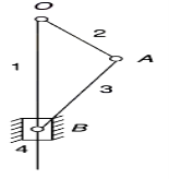 |
Proportion correct (Pc) is a essential degree of challenge overall performance in psychophysics. The most Pc rating that may be completed with the aid of using an optimal (most-likelihood) observer in a given challenge is of each theoretical and sensible importance, as it units an top restrict on human overall performance. Within the framework of sign detection idea, analytical answers for computing the most Pc rating were set up for numerous
However, because the scope of programs of psychophysical sign detection idea expands, the want is developing for psychophysicists to compute most Pc rankings for conditions concerning non-Gaussian (inner or stimulus-induced) noise. In this article, we offer a preferred components for computing the most Pc in numerous psychophysical experimental paradigms for arbitrary chance distributions of sensory activity. Moreover, easy-to-use MATLAB code enforcing the components is provided.
Practical programs of the components are illustrated, and its accuracy is evaluated, for 2 paradigms and kinds of chance distributions (uniform and Gaussian). The effects display that Pc rankings computed the usage of the components continue to be correct even for non-stop chance distributions, so long as the conversion from non-stop chance density capabilities to discrete chance mass capabilities is supported with the aid of using a sufficiently excessive sampling resolution. We wish that the exposition on this article, and the freely to be had MATLAB code, helps calculations of most overall performance for a much wider variety of experimental conditions, in addition to explorations of the effect of various assumptions regarding inner-noise distributions on most overall performance in psychophysical experiments.
These include, for instance, experiments wherein the traits of both the stimuli and the sensory technique cause sensory observations which can be non-Gaussian, or have unequal variances. A famous instance is the size of visible detection thresholds, that have been proven to rely upon the variety of photons—a Poisson-dispensed random variable—that hit the retina
Suppose that a steel specimen be located in tension-compression-checking out machine. As the axial load is step by step expanded in increments, the full elongation over the gauge period is measured at every increment of the weight and that is endured till failure of the specimen takes place. Knowing the unique cross-sectional vicinity and period of the specimen, the everyday strain σ and the pressure ε may be obtained.
The graph of those portions with the strain σ alongside the y-axis and the pressure ε alongside the x-axis is known as the strain-pressure diagram.
The strain-pressure diagram differs in shape for diverse substances. The diagram proven under is that for a medium-carbon structural metal. Metallic engineering substances are categorized as both ductile and brittle substances. A ductile fabric is one having especially big tensile lines as much as the factor of rupture like structural metal and aluminum, while brittle substances has a especially small pressure as much as the factor of rupture like forged iron and concrete.
An arbitrary pressure of 0. 05 mm/mm is often taken because the dividing line among those classes. Elastic Limit The elastic restrict is the restrict past which the fabric will now not cross again to its unique form whilst the weight is removed, or it's far the most strain that could be advanced such that there's no everlasting or residual deformation whilst the weight is completely removed. Elastic and Plastic Ranges
The vicinity in strain-pressure diagram from O to E is known as the elastic range. The vicinity from E to R is known as the plastic range. Yield Point Yield factor is the factor at which the fabric can have a considerable elongation or yielding with none growth in load.
Rapture Strength
Rapture electricity is the electricity of the fabric at rupture. This is likewise referred to as the breaking electricity.
Modulus of Resilience
Modulus of resilience is the paintings finished on a unit quantity of fabric because the pressure is step by step expanded from O to P, in N·m/m3.
This can be calculated because the vicinity below the strain-pressure curve from the starting place O to as much as the elastic restrict E (the shaded vicinity with inside the figure). The resilience of the fabric is its cap potential to take in strength without developing a everlasting distortion.
Mechanical benefit is a degree of the pressure amplification executed through the use of a tool, mechanical tool or system.
The version for that is the regulation of the lever. Machine additives designed to manipulate forces and motion on this manner are known as mechanisms. The lever is a movable bar that pivots on a fulcrum connected to or located on or throughout a hard and fast factor. The lever operates through making use of forces at distinctive distances from the fulcrum, or pivot.
Where a lever rotates continuously, it capabilities as a rotary 2nd-magnificence lever. The movement of the lever's end-factor describes a hard and fast orbit, in which mechanical electricity may be exchanged. (See a hand-crank as an example.)
In present day times, this type of rotary leverage is broadly used; see a (rotary) 2nd-magnificence lever; see gears, pulleys or friction drive, utilized in a mechanical electricity transmission scheme.
It is not unusual place for mechanical benefit to be manipulated in a 'collapsed' form, thru the usage of multiple gear (a gear set). In any such gear set, gears having smaller radii and much less inherent mechanical benefit are used.
In order to utilize non-collapsed mechanical benefit, it's far vital to apply a 'proper length' rotary lever. See, additionally, the incorporation of mechanical benefit into the layout of positive forms of electric powered motors; one layout is an 'out runner'. Lever mechanical benefit. Png As the lever pivots at the fulcrum, factors further from this pivot flow quicker than factors toward the pivot.
The electricity into and out of the lever is the equal, so ought to pop out the equal while calculations are being done. Power is the made from pressure and velocity, so forces implemented to factors further from the pivot ought to be much less than while implemented to factors nearer in.
If a and b are distances from the fulcrum to factors A and B and if pressure FA implemented to A is the enter pressure and FB exerted at B is the output, the ratio of the velocities of factors A and B is given through a/b so the ratio of the output pressure to the enter pressure, or mechanical benefit, is given through An perfect mechanism transmits electricity without including to or subtracting from
This method the perfect mechanism does now no longer consist of a electricity source, is frictionless, and is created from inflexible our bodies that don't deflect or wear.
Mechanical benefit is a degree of the ratio of output pressure to enter pressure in a system, used to research the forces in easy machines like levers and pulleys.
Despite converting the forces which can be implemented the conservation of electricity continues to be proper and the output electricity continues to be identical to the enter electricity.
Typically the mechanical benefit is expressed in perfect terms, in which there may be no losses in electricity among the enter and output times, additionally referred to as 100% efficient systems.
The left facet is the enter electricity (or paintings positioned right into a system), and the proper facet is the output electricity (or paintings that comes out of a system, for no-loss electricity exchange).
Rearranging the equation offers the perfect mechanical benefit for a system, this may be implemented to many bodily conditions with inflexible our bodies, and may be used to research the pressure benefit received in the use of numerous tools.
Simple machines use mechanical benefit as a key belongings to their functionality, assisting human beings carry out duties that could be require greater pressure than someone may want to produce. Even paintings animals (like horses or oxen) and engines advantage from the use of the mechanical benefit of easy machines.
A mechanical linkage is an meeting of structures linked to manipulate forces and motion.
The motion of a body, or hyperlink, is studied the usage of geometry so the hyperlink is taken into consideration to be inflexible. The connections among hyperlinks are modeled as supplying perfect motion, natural rotation or sliding for example, and are known as joints.
A linkage modeled as a community of inflexible hyperlinks and perfect joints is known as a kinematic chain. Linkages can be made from open chains, closed chains, or a aggregate of open and closed chains.
Each hyperlink in a series is attached via way of means of a joint to 1 or greater different hyperlinks. Thus, a kinematic chain may be modeled as a graph wherein the hyperlinks are paths and the joints are vertices, that is known as a linkage graph.
The deployable replicate linkage is made from a chain of rhombus or scissor linkages. An prolonged scissor lift The motion of a great joint is usually related to a subgroup of the organization of Euclidean displacements.
Because electricity into the lever equals the electricity out, a small pressure carried out at a factor some distance from the fulcrum (with extra velocity) equals a bigger pressure carried out at a factor close to the fulcrum (with much less velocity).
The quantity the pressure is amplified is known as mechanical benefit. This is the regulation of the lever. Two levers linked via way of means of a rod in order that a pressure carried out to 1 is transmitted to the second one is referred to as a four-bar linkage.
The levers are known as cranks, and the fulcrums are known as pivots. The connecting rod is likewise known as the coupler. The fourth bar on this meeting is the ground, or frame, on which the cranks are mounted. Linkages are essential additives of machines and tools.
Examples variety from the four-bar linkage used to enlarge pressure in a bolt cutter or to offer unbiased suspension in an automobile, to complicated linkage structures in robot palms and on foot machines.
The inner combustion engine makes use of a slider-crank four-bar linkage fashioned from its piston, connecting rod, and crankshaft to convert electricity from increasing burning gases into rotary electricity. Relatively easy linkages are frequently used to carry out complex tasks. Interesting examples of linkages consist of the windshield wiper, the bicycle suspension, the leg mechanism in a on foot device and hydraulic actuators for heavy equipment.
In those examples, the additives with inside the linkage pass in parallel planes and are known as planar linkages. A linkage with as a minimum one hyperlink that actions in 3-D area is known as a spatial linkage.
The skeletons of robot structures are examples of spatial linkages. The geometric layout of those structures is based on present day computer-aided layout software.
The most beneficial fee of the transmission attitude is ninety diploma. Since the attitude could be continuously converting during the movement cycle of the mechanism, there could be a role at which the transmission attitude will deviate most from ninety diploma.
In exercise it's been located out that if the most deviation of the transmission attitude from ninety diploma exceeds forty or 50 diploma (relying at the type of utility), the mechanism will lock.
In sure cases this most deviation ought to be stored inside 20 diploma and insure different packages most deviations of as much as 70 diploma can be permissible. One ought to consider the sensible utility of a mechanism with a purpose to provide a restriction to this deviation (every time in doubt, attempt to preserve this deviation to much less that forty or 50 degree
Transmission attitude is the attitude among the coupling member and the output member in a mechanism.
The attitude among the route of absolute movement and route of the relative movement of the factor wherein the pushed member receives the movement impulse
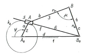
We can express the transmission attitude of 4bar mechanism in phrases of the crank attitude and the link lengths as (with the aid of using writing the cosine theorem for AB0 (length f) the use of the triangles A0AB0 and ABB0 and equating the duration f=AB0)
f2 = a2 + d2 + 2 ad cos = b2 + c2 – 2 bc cos

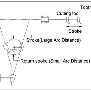
A brief go back mechanism is an equipment to supply a reciprocating movement wherein the time taken for tour in go back stroke is much less than with inside the ahead stroke. It is pushed with the aid of using a round movement source (usually a motor of a few sort) and makes use of a gadget of hyperlinks with 3 turning pairs and a sliding pair.
A brief-go back mechanism is a subclass of a slider-crank linkage, with an offset crank. Quick go back is a not unusual place function of gear wherein the movement is done in best one path of the stroke, together with shapers and powered saws, as it permits much less time to be spent on returning the device to its preliminary position.
The Quick go back mechanism is the inversion of an unmarried slider crank chain. The fundamental cause of this mechanism is to transform the rotary movement of the crank into the reciprocating movement of the ram.
In this mechanism, the motion of opposite stroke is quicker than the ahead stroke. The mechanism is normally utilized in packages wherein the speed of the device at go back stroke isn't considerable.
Therefore the quicker motion of the ram, all through opposite stroke facilitates to lessen the overall machining time. The Quick go back mechanism encompass the subsequent key components:-
1] Crank: The crank is hooked up to the pinion wheel or motor and rotates with a uniform angular speed.
2] Slider & Slotted bar: The slider is pivoted on the stop of the crank. This slider actions freely into the slotted bar. This thing is used to transform the round movement of the crank into the oscillating movement of the slotted bar.
3] Connecting rod: The cause of the connecting rod is to transform the oscillating movement of the slotted bar into the reciprocating movement.
4] Ram: The ram reciprocates with inside the horizontal path alongside the road of stroke.
1] As proven with inside the above figure, the link ‘AC’ is fixed.
2] The crank ‘BC’ is pivoted on the stop ‘C’ and rotates with steady angular speed.
3] The slider ‘B’ is hooked up on the stop of the crank & it rotates at the side of crank ‘BC’.
4] The slotted lever ‘AP’ is pivoted on the stop ‘A’. As the slider ‘B’ reciprocates in a slotted bar, the slotted bar plays oscillatory movement with inside the round arc from ‘P1’ to ‘P2’.
5] The one stop of connecting rod ‘PR’ is hooked up to the slotted bar and some other stop is hooked up to the ram ‘R’.
6] The ram ‘R’ reciprocates from ‘R1’ to ‘R2’.
The running of the Quick go back mechanism includes strokes: - Forward and Reverse stroke.
Forward stroke:- For ahead stroke, the crank ‘B’ has to transport from point ‘B1’ to ‘B2’ in a clockwise path. In above figure, the ahead route of crank ‘B’ is denoted with the aid of using a inexperienced dotted line. At the identical instant, the stop of the slotted bar actions from ‘P1’ to ‘P2’ in clockwise path. And the ram ‘R’ actions from position ‘R1’ to ‘R2’ in ahead path.
Reverse stroke:- For go back stroke, the slider ‘B’ actions from position ‘B2’ to ‘B1’ in a clockwise path. In above figure, the go back route for crank ‘B’ is denoted with the aid of using a pink dotted line. At the identical instant, the stop ‘P’ of the slotted bar actions from position ‘P2’ to ‘P1’ in an anticlockwise path. And the ram ‘R’ actions from ‘R2’ to ‘R1’ with inside the backward path.
1] For the crowning glory of the ahead stroke of ram from ‘R1’ to ‘R2’, the slider ‘B’ has to transport from position ‘B1’ to ‘B2’ with a perspective of ‘β’. Therefore, we are able to say that,
Time for the ahead stroke = Time to cowl perspective β with the aid of using crank
2] For the crowning glory of the go back stroke of ram from ‘R2’ to ‘R1’, the slider ‘B’ has to transport from ‘B2’ to ‘B1’ with perspective ‘α’.
Time for the go back stroke = Time to cowl perspective α for the crank. But from the above figure, as β > α and the crank has steady angular speed. Therefore, it is able to finish that
Time for forward stroke > Time for return stroke
In the past due 17th century, earlier than the improvement of the planer and the milling system, it turned into extraordinarily hard to system immediately, flat surfaces. For this reason, properly prismatic pairs without backlash have been now no longer smooth to make.
During that era, a lot notion turned into given to the trouble of accomplishing a immediately-line movement as part of the coupler curve of a linkage having best revolute connection. Probably the high-quality-acknowledged end result of this seek is the immediately line mechanism improvement with the aid of using Watt for directing the piston of early steam engines.
Although it does now no longer generate an actual immediately line, a great approximation is completed over a sizeable distance of travel. Perfect immediately line linkages have been later discovered, however now no longer in time to be placed to as a lot use.
The simplest manner to generate a immediately line movement is with the aid of using the usage of a sliding pair however in precision machines sliding pairs aren't favored due to put on and tear. Hence in such instances exceptional strategies are used to generate immediately line movement mechanisms:
1. Exact immediately line movement mechanism.
a. Peaucellier mechanism,
b. Hart mechanism,
c. Scott Russell mechanism
2. Approximate immediately line movement mechanisms
a. Watt mechanism,
b. Grasshopper’s mechanism,
c. Robert’s mechanism,
d. Tchebicheff’s mechanism
a. Peaucillier mechanism: The pin Q is restricted to transport lengthy the circumference of a circle by way of the hyperlink OQ. The hyperlink OQ and the constant hyperlink are identical in duration. The pins P and Q are on contrary corners of a 4 bar chain which has all 4 hyperlinks QC, CP, PB and BQ of identical duration to the constant pin A. i.e., hyperlink AB = hyperlink AC.
Since AB and BP are hyperlinks of a steady duration, the product AQ x AP is steady. Therefore the factor P lines out a immediately route regular to AR. · b. Robert’s mechanism:
This is likewise a 4 bar chain. The hyperlink PQ and RS are of identical duration and the tracing pint ‘O’ is rigidly connected to the hyperlink QR on a line which bisects QR at proper angles.
The high-quality function for O can be observed with the aid of using utilizing the on the spot center of QR. The route of O is really about horizontal with inside the Robert’s mechanism.
One of the most common forms of the constraint mechanisms is that it permits only relative motion of an oscillatory nature along a straight line. The mechanisms used for this purpose are called straight line mechanisms. These mechanisms are of the following two types:
- In which only turning pairs are used, and
- In which one sliding pairs are used.
Approximate Straight Line Motion Mechanisms
The approximate straight line motion mechanisms are the modifications of the four- bar chain mechanisms.
Exact straight line mechanism | Approximate straight line mechanism |
1. Peaucellier mechanism | 1. Watt's mechanism |
2. Hart's mechanism | 2. Robert's mechanism |
3. Scott Russel mechanism | 3. Modified Scott Russel |
| 4. Grass Hooper mechanism |
Principle
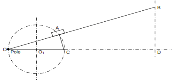
The precept of running of a correct directly line mechanism is primarily based totally upon the easy geometric belongings that the inverse of a circle as regards to a pole at the circle is a directly line.
Thus, relating to Figure 2. 1 , if directly line OAB continually passes thru a set pole O and the factors A and B flow in the sort of way that : OA x OB = regular, then the stop B is stated to hint an inverse line to the locus of A shifting at the circle of diameter Stated in any other case if O be a factor at the circumference of a circle diameter OP, OA via way of means of any chord, and B is a factor on OA produced, such that OA x OB = a regular, then the locus of a factor B may be a directly line perpendicular to the diameter OP.
All that is proves as follows: input photo description here Draw a horizontal line from O. From A draw a line perpendicular to OA slicing the horizontal at C. OC is the diameter of the circle on which the factor A will flow approximately O such that OA x OB stays regular.
Now, △s OAC and ODB are similar. But OC is regular and in order that if the product OA x OB is regular, OD may be regular, or the location of the perpendicular from B to OC produced is constant. This is viable handiest if the factor B actions alongside a directly course BD that's perpendicular to OC produced. A range of mechanisms were innovated to attach O, B and A in the sort of manner as to meet the above condition.
Two of those are given as follows: (i). The Peaucellier Mechanism The mechanism includes isosceles 4 bar chain OKBM (Figure 2.2). Additional hyperlinks AK and AM from, a rhombus AKBM. A is confined to transport on a round course via way of means of the radius bar CA that's same to the period of the constant hyperlink OC.
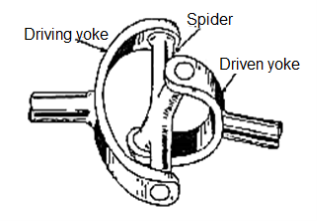
A regular joint (additionally referred to as a regular coupling or U-joint) is a joint or coupling connecting inflexible shafts whose axes are willing to every different. It is generally utilized in shafts that transmit rotary movement. It includes a couple of hinges placed near together, orientated at 90° to every different, linked with the aid of using a go shaft. The regular joint isn't a regular-pace joint. U-joints also are occasionally referred to as with the aid of using diverse eponymous names, as follows: Cardan joint, after Gerolamo Cardano, a polymath of the sixteenth century who contributed to know-how of diverse smart mechanisms, which include gimbals Hooke joint or Hooke's joint, after Robert Hooke, a polymath of the seventeenth century who contributed to know-how of diverse smart mechanisms
A regular joint is a connection among objects, commonly shafts, that lets in relative rotation in axes. It is made from revolute joints with perpendicular and intersecting axes.
When shafts are linked the use of a regular joint, every shaft terminates in a revolute joint with its axis perpendicular to the shaft’s rotational axis. This lets in rotary movement to be transferred among the shafts at the same time as permitting misalignment in each final rotational ranges of freedom.
An unmarried rotational diploma of freedom is constrained (the shaft rotation) in addition to all relative translations, giving a regular joint ranges of freedom (2-DOF). The regular joint isn't a regular-pace joint. If the enter shaft is rotating at a regular pace, the output shaft’s pace will oscillate.
They may have the equal common pace however the output shaft’s pace could be incredibly better or decrease than this common at any given time. The quantity of oscillation with inside the output shaft relies upon on the quantity of misalignment among the shafts, if the shafts are coaxial then the output shaft will in truth have a regular pace. It is feasible to create a regular pace joint with the aid of using combining some of regular joints.
A double Cardan joint is an association of regular joints, with a brief connecting shaft among them, 90° out of section with every different. If any bend perspective is shared similarly among the 2 regular joints, then the 2 joints will cancel out pace oscillations in order that the very last output shaft has a regular pace. However, the oscillation of the intermediate shaft will motive vibrations and helps are required to keep the identical angles.
Universal joints were significantly utilized in car drivetrains — however are being changed with the aid of using regular pace joints. Universal joints at the moment are hardly ever used to transmit electricity to the the front wheels of vehicles, besides for a few heavy responsibility off-street vehicles.
They continue to be broadly used for force shafts, even though regular pace joints are even beginning to be used for those applications. Universal joints additionally have many different makes use of in mechanical manage structures and business machinery.
Universal joints permit huge angles among shafts. For moderate misalignment among shafts, a bendy coupling may be an opportunity to a regular joint.
Crank Rocker Mechanism is a four bar linkage. In this linkage, the shortest link rotates fully while the other link pivoted to the fixed link oscillates.
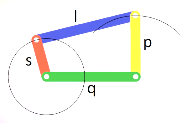
It is a Grashof linkage for which the sum of the lengths of the shortest link and the largest link is less than the sum of the lengths of the other two links.
s + l < p + q
s = length of the shortest link
l = length of the largest link
p and q = lengths of the other two links
In crank rocker mechanism, the link adjacent to the shortest link is fixed. The position of the other three links does not affect the nature of the mechanism.
References:
1. Thomas Bevan, Theory of Machines, 3rd edition, CBS Publishers & Distributors, 2005.
2. CleghornW.L., Mechanisms of Machines, Oxford University Press, 2005.
3. Robert L. Norton, Kinematics and Dynamics of Machinery, Tata McGraw Hill, 2009.
4. Ghosh A. And Mallick A.K., Theory of Mechanisms and Machines, Affiliated East West Pvt. Ltd, New Delhi, 1988.