Unit - 3
Surface contacts
Classification of Cams
Cams can be classified based on their physical shape.
Disk or plate cam: The disk (or plate) cam has an irregular contour to impart a specific motion to the follower. The follower moves in a plane perpendicular to the axis of rotation of the cam shaft and is held in contact with the cam by springs or gravity.
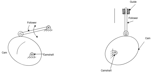
Fig. 1: Disk or plate arm
Cylindrical cam: The cylindrical cam has a groove cut along its cylindrical surface. The roller follows the groove, and the follower moves in a plane parallel to the axis of rotation of the cylinder.

Fig. 2: Cylindrical cam
Translating cam:
The translating cam is a contoured or grooved plate sliding on a guiding surface(s). The follower may oscillate (Fig.3 a) or reciprocate (Fig. 3b). The contour or the shape of the groove is determined by the specified motion of the follower.

Fig. 3: Translating cam
Classification of Followers
Based on surface in contact
Knife edge
Roller follower
Flat faced
Spherical follower
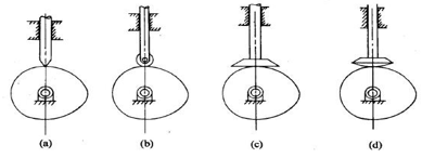
Fig. 4: Follower classification based on surface in contact
Based on type of motion
Oscillating
Translating
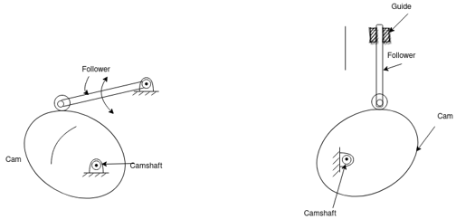
Fig. 5: Follower classification based on type of motion
Based on line of motion
Radial follower: The lines of movement of in-line cam followers pass through the centers of the camshafts.
Off-set follower: For this type, the lines of movement are offset from the centers of the Cam shafts.
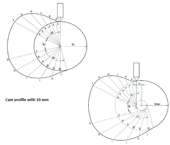
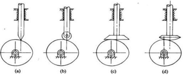
Fig. 6: Classification of cam on the basis of line of motion
Key Takeaway
Based on surface in contact, based on type of motion, Based on line of motion.
Displacement diagrams: In a cam follower system, the motion of the follower is very important. Its displacement can be plotted against the angular displacement θ of the cam and it is called as the displacement diagram. The displacement of the follower is plotted along the y-axis and angular displacement θ of the cam is plotted along x-axis. From the displacement diagram, velocity and acceleration of the follower can also be plotted for different angular displacements θ of the cam. The displacement, velocity and acceleration diagrams are plotted for one cycle of operation i.e., one rotation of the cam. Displacement diagrams are basic requirements for the construction of cam profiles. Construction of displacement diagrams and calculation of velocities and accelerations of followers with different types of motions are discussed in the following sections.
(a) Follower motion with Uniform velocity:
Fig.2 shows the displacement, velocity and acceleration patterns of a follower having uniform velocity type of motion. Since the follower moves with constant velocity, during rise and fall, the displacement varies linearly with θ. Also, since the velocity changes from zero to a finite value, within no time, theoretically, the acceleration becomes infinite at the beginning and end of rise and fall.
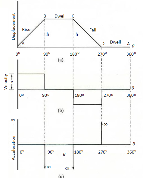
Fig. 7: Follower motion with Uniform velocity
(b) Follower motion with modified uniform velocity:
It is observed in the displacement diagrams of the follower with uniform velocity that the acceleration of the follower becomes infinite at the beginning and ending of rise and return strokes. In order to prevent this, the displacement diagrams are slightly modified. In the modified form, the velocity of the follower changes uniformly during the beginning and end of each stroke. Accordingly, the displacement of the follower varies parabolically during these periods. With this modification, the acceleration becomes constant during these periods, instead of being infinite as in the uniform velocity type of motion. The displacement, velocity and acceleration patterns are shown in fig. 3.
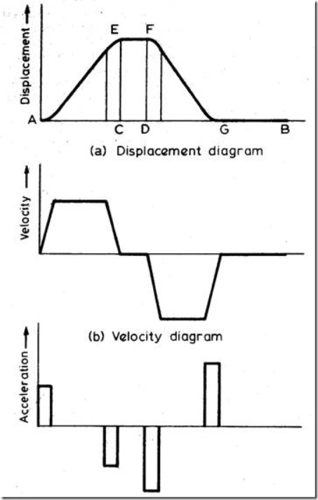
Fig 8: Follower motion with modified uniform velocity
(c) Follower motion with uniform acceleration and retardation (UARM):
Here, the displacement of the follower varies parabolically with respect to angular displacement of cam. Accordingly, the velocity of the follower varies uniformly with respect to angular displacement of cam. The acceleration/retardation of the follower becomes constant accordingly. The displacement, velocity and acceleration patterns are shown in fig. 4.
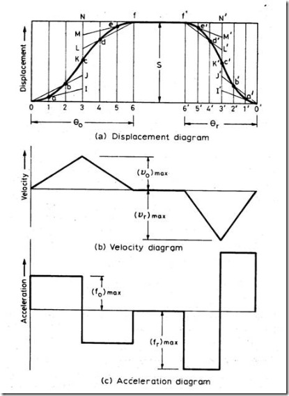
Fig 9: Follower motion with uniform acceleration and retardation
s = Stroke of the follower
θo and θr = Angular displacement of the cam during outstroke and return stroke.
ω = Angular velocity of cam.
Time required for follower outstroke = to = θ0/
Time required for follower return stroke = tr = θr/
Average velocity of follower = s/t
Average velocity of follower during outstroke = 
Vomin = 0
vomax = 2s/t0 = 2s/θ0 = Max. Velocity during outstroke.
Average velocity of follower during return stroke = 
Vrmin = 0
vrmax = 2s/tr = 2s/θr = Max. Velocity during return stroke.
Acceleration of the follower during outstroke = a0 = vomax/t0/2 = 42s/θ02
Similarly acceleration of the follower during return stroke = ar = 42s/θr2
(d) Simple Harmonic Motion: In fig.5, the motion executed by point Pl, which is the projection of point P on the vertical diameter is called simple harmonic motion. Here, P moves with uniform angular velocity ωp, along a circle of radius r (r = s/2).
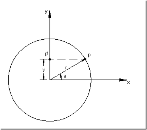
Fig 10: Simple Harmonic Motion
Displacement = y = r sin α = r sin Ft ; ymax = r [d1]
Velocity =  Fr cos Ft ;
  rF [d2]
Acceleration =  - F2 r sin Ft = - F2y ;
  F2 [d3]
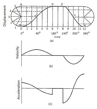
Fig 11: Follower Displacement Diagram with Simple Harmonic Motion
s= Stroke or displacement of the follower.
θo = Angular displacement during outstroke.
θr = Angular displacement during return stroke
ω = Angular velocity of cam.
to = Time taken for outstroke = θ0/
tr = Time taken for return stroke = θr/
Max. Velocity of follower during outstroke = vomax = rωp (from d2)
Vomax = s/2 π/t0 = πs/2θ0
Similarly Max. Velocity of follower during return stroke = , vrmax = s/2 π/tr = πs/2θr
Max. Acceleration during outstroke = aomax = rω2p (from d3) = s/2 (π/t0)2 = π22s/2θ02
Similarly, Max. Acceleration during return stroke = armax = s/2 (π/tr)2 = π22s/2θr2
(e) Cycloidal motion:
Cycloid is the path generated by a point on the circumference of a circle, as the circle rolls without slipping, on a straight/flat surface. The motion executed by the follower here, is similar to that of the projection of a point moving along a cyloidal curve on a vertical line as shown in figure 7.
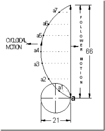
Fig 12: Cycloidal motion
The construction of displacement diagram and the standard patterns of velocity and acceleration diagrams are shown in fig.8. Compared to all other follower motions, cycloidal motion results in smooth operation of the follower.
The expressions for maximum values of velocity and acceleration of the follower are shown below.
s = Stroke or displacement of the follower.
d = dia. Of cycloid generating circle = s/π
θo = Angular displacement during outstroke.
θr = Angular displacement during return stroke
ω = Angular velocity of cam.
to = Time taken for outstroke = θ0/
tr = Time taken for return stroke = θr/
Vomax = Max. Velocity of follower during outstroke = 2s/θ0
Vrmax = Max. Velocity of follower during return stroke = 2s/θr
Aomax = Max. Acceleration during outstroke = 2π2s/θ02
Armax = Max. Acceleration during return stroke = 2π2s/θr2
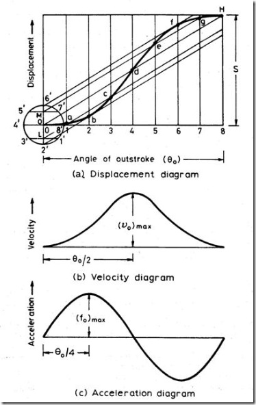
Fig 13: Follower Displacement, Velocity & Acceleration Diagram for Cycloidal Motion
The pace of an item may be described because the price of extrude of the item’s role with recognize to a body of reference and time. Velocity is a vector quantity, because of this that we want each significance (speed) and path to outline pace. The SI unit is a meter in step with second (ms-1). If there may be a extrude in significance or the path with inside the pace of a frame the frame is stated to be accelerating.
Uniform Velocity The situation wherein a frame covers identical distance in an identical c program language period of time is thought to be uniform pace. In equation(d = v t) v is the common pace of a frame in the course of time t. II each its significance and path do now no longer extrude with time then it is able to be stated that the frame is at uniform pace.
Examples
Listed underneath are the examples of uniform motion
The rotation of the Moon across the earth
Movement of palms of a watch Rotation of Earth Revolution of Earth
Parabolic motions:
Projectile motion, also known as parabolic motion, consists in launching a body with a velocity that form an angle α with the horizontal. In the following figure, you can see a representation of the situation.
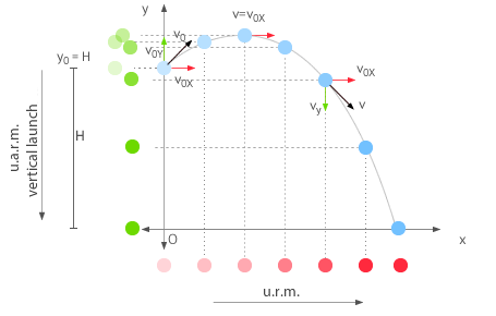
This motion is characteristic of projectiles, moving objects being affected only by gravity. On the x-axis, the body moves at constant velocity v0x (u.r.m.) and in the y-axis with constant acceleration due to gravity (u.a.r.m.).
It is characterized by the fact that at the highest point of the trajectory, the velocity of the body is always v0x (there is no vy).
The equations for projectile motion are:
- The equations for the u.r.m. On the x-axis
x=x0+vx·t
- The equations for the u.a.r.m. On the y-axis
Vy=v0y+ay·t
y=y0+v0y·t+12·ay·t2
Since, as we said above, the velocity forms an angle α with the horizontal, the x and y components are determined using the most common trigonometric relationships:
According to the trigonometric relationships:
vx = v . Cos α vy = v . Sin α
Tan α = vy/vx
According to the Pythagorean theorem:
v = vx2 + vy2
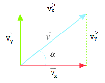
Decomposition of the velocity vector
Any vector, including the velocity, can be broken down is in 2 vectors, vx and vy, that have the same directions as the Cartesian axes. The magnitude of both vectors can be calculated from the angle that the vector forms with the horizontal through the expressions shown in the figure.
Simple harmonic motions:
Simple harmonic motion can be described as an oscillatory motion in which the acceleration of the particle at any position is directly proportional to the displacement from the mean position. It is a special case of oscillatory motion.
All the Simple Harmonic Motions are oscillatory and also periodic but not all oscillatory motions are SHM. Oscillatory motion is also called the harmonic motion of all the oscillatory motions wherein the most important one is simple harmonic motion (SHM).
In this type of oscillatory motion displacement, velocity and acceleration and force vary (w.r.t time) in a way that can be described by either sine (or) the cosine functions collectively called sinusoids.
Consider a particle of mass (m) executing Simple Harmonic Motion along a path x o x; the mean position at O. Let the speed of the particle be v0 when it is at position p (at a distance no from O)
At t = 0 the particle at P (moving towards the right)
At t = t the particle is at Q (at a distance x from O)
With a velocity (v)
The restoring force


K – is positive constant


Put,


Since,


d2x/dt2 + 2x = 0, which is the differential equation for linear simple harmonic motion.
Cycloidal motions:
In geometry, a cycloid is the curve traced by a point on a circle as it rolls along a straight line without slipping. A cycloid is a specific form of trochoid and is an example of a roulette, a curve generated by a curve rolling on another curve.
The cycloid, with the cusps pointing upward, is the curve of fastest descent under constant gravity (the brachistochrone curve). It is also the form of a curve for which the period of an object in simple harmonic motion (rolling up and down repetitively) along the curve does not depend on the object's starting position (the tautochrone curve).
Kinematic derivatives:
Displacement diagram: Displacement of follows (s) Vs Cam angle (0)
If s = s(0)
s(0) = ds/dθ
(It is the slope in a displacement curve at each position of cam angle 0. High value of slope in a different curve, indicates a steep rise or fall or follower which hampers smooth running of the cam.)
s(0) = d2s/dθ2
(It is inverse of the radius of curvature of the cam at different points along the cam profile. When the value of second derivatives becomes infinity. i.e. the radius of curvature of cam profile is small and hence the profile becomes pointed. This avoids smooth movement of follower over cam and also causes higher stresses between cam and follower surfaces.)
Physical derivatives:
Displacement of follower s = s(0), and
Angular rotation of cam 0 = 0(t)
Velocity of follower s = ds/dt = ds/dθ. dθ/dt = ds/dθ
Acceleration of follower s = d2s/dt2 = 2 d2s/dθ2
(A higher value of acceleration means a higher inertia force.)
Jerk s = d3s/dt3 = 3 d3s/dθ3
The transformation of one of the easy motions, consisting of rotation, into some other motions is regularly effortlessly finished with the aid of a cam mechanism a cam mechanism normally includes shifting elements, the cam and the follower, installed on a set frame. Cam gadgets are versatile, and nearly any arbitrarily-specific movement may be obtained. In a few instances, they provide the handiest and maximum compact manner to convert motions. A cam can be described as a gadget detail having a curved define or a curved groove, which, with the aid of using its oscillation or rotation movement, offers a predetermined specific movement to any other detail known as the follower.
The cam has a totally critical feature with inside the operation of many instructions of machines, mainly the ones of the automated type, consisting of printing presses, shoe equipment, fabric equipment, gear-slicing machines, and screw machines. In any magnificence of equipment wherein computerized manage and correct timing are paramount, the cam is an quintessential a part of mechanism.
The feasible programs of cams are unlimited, and their shapes arise in extraordinary variety. Some of the maximum not unusual place paperwork could be taken into consideration on this chapter. Trace factor: A theoretical factor at the follower, similar to the factor of a fictitious knife-aspect follower. It is used to generate the pitch curve. In the case of a curler follower, the hint factor is on the middle of the curler.
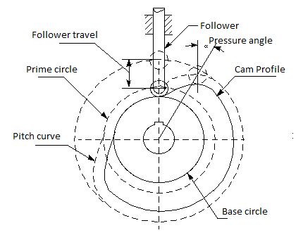
Pitch curve: The route generated with the aid of using the hint factor on the follower is circled approximately a desk bound cam.
Working curve: The running floor of a cam in touch with the follower. For the knife-aspect follower of the plate cam, the pitch curve and the running curves coincide. In a near or grooved cam there's an internal profile and an outer running curve.
Pitch circle: A circle from the cam middle via the pitch factor. The pitch circle radius is used to calculate a cam of minimal length for a given strain perspective.
Prime circle (reference circle): The smallest circle from the cam middle via the pitch curve.
Base circle: The smallest circle from the cam middle via the cam profile curve.
Stroke or throw: The finest distance or perspective via which the follower movements or rotates.
Follower displacement: The role of the follower from a particular 0 or relaxation role (normally it’s the placement whilst the f follower contacts with the bottom circle of the cam) with regards to time or the rotary perspective of the cam.
Pressure perspective: The perspective at any factor among the ordinary to the pitch curve and the immediately route of the follower movement. This perspective is critical in cam layout as it represents the steepness of the cam profile.
A cylindrical cam or barrel cam is a cam wherein the follower rides at the floor of a cylinder. In the maximum not unusual place type, the follower rides in a groove reduce into the floor of a cylinder. These cams are basically used to transform rotational movement to linear movement parallel to the rotational axis of the cylinder. A cylinder may also have numerous grooves reduce into the floor and pressure numerous followers.
Cylindrical cams can offer motions that contain greater than a unmarried rotation of the cylinder and normally offer superb positioning, putting off the want for a spring or different provision to hold the follower in touch with the manipulate floor. Applications consist of device drives, together with reciprocating saws, and shift manipulate barrels in sequential transmissions, together with on maximum present day motorcycles.
A unique case of this cam is a steady lead, wherein the placement of the follower is linear with rotation, as in a lead screw. The reason and element of implementation have an effect on whether or not this utility is known as a cam or a screw thread, however in a few cases, the nomenclature can be ambiguous. Cylindrical cams will also be used to reference an output to 2 inputs, wherein one enter is the rotation of the cylinder and the opposite is the placement of the follower alongside the cam.
The output is radial to the cylinder. These have been as soon as not unusual place for unique capabilities on top of things systems, together with hearth place manipulate mechanisms for weapons on naval vessels and mechanical analogy computers. An instance of a cylindrical cam with inputs is furnished with the aid of using a duplicating lathe, an instance of that is the Klotz awl manage lathe, which cuts an awl manage to a shape managed with the aid of using a sample appearing as a cam for the lathe mechanism.
A face cam produces movement through the usage of a follower driving at the face of a disk. The maximum not unusual place kind has the follower journey in a slot in order that the captive follower produces radial movement with tremendous positioning without the want for a spring or different mechanism to maintain the follower in touch with the manipulate surface. A face cam of this kind normally has handiest one slot for a follower on every face. In a few applications, a unmarried detail, inclusive of a gear, a barrel cam or different rotating detail with a flat face, might also additionally do obligation as a face cam further to different purposes.
Face cams might also additionally offer repetitive movement with a groove that bureaucracy a closed curve or might also additionally offer characteristic era with a stopped groove. Cams used for characteristic era might also additionally have grooves that require numerous revolutions to cowl the whole characteristic, and on this case, the characteristic normally wishes to be invertible in order that the groove does now no longer self-intersect, and the characteristic output price should vary sufficient at corresponding rotations that there's enough fabric setting apart the adjoining groove segments.
A not unusual place shape is the steady lead cam, wherein the displacement of the follower is linear with rotation, inclusive of the scroll plate in a scroll chuck. Non-invertible features, which require the groove to self-intersect, may be carried out the usage of unique follower designs.
Sash window lock, conventional cam style, for double-hung sash window a version of the face cam affords movement parallel to the axis of cam rotation. A not unusual place instance is the conventional sash window lock, wherein the cam is set up to the pinnacle of the decrease sash, and the follower is the hook at the top sash. In this application, the cam is used to offer a mechanical benefit in forcing the window shut, and additionally affords a self-locking action, like a few Trojan horse gears, because of friction.
The output is parallel to the axis of the cam. These have been as soon as not unusual place is mechanical analogy computation and unique features on top of things systems.
A face cam that implements 3 outputs for a unmarried rotational enter is the stereo phonograph, wherein a quite steady lead groove publications the stylus and tone arm unit, appearing as both a rocker-kind (tone arm) or linear (linear monitoring turntable) follower, and the stylus on my own appearing because the follower for 2 orthogonal outputs to representing the audio signals. These motions are in a aircraft radial to the rotation of the document and at angles of forty five tiers to the aircraft of the disk (ordinary to the groove faces). The role of the tonearm become utilized by a few turntables as a manipulate enter, inclusive of to show the unit off or to load the subsequent disk in a stack, however become not noted in easy units.
The undercut of gears is likewise referred to as deeper reducing and shows the phenomenon of reducing the basis of the tools deeper than the involute teeth curve. This can occur while there's interference among a teeth reducing device and a tools or among the 2 meshing gears.
When the undercutting is large, the basis of the tools will become narrower and the teeth shape will become vulnerable in its bending strength. The principal cause for undercutting to arise is, while reducing a tools with a small variety of enamel (for trendy tools with 20° stress attitude, variety of enamel z = 17 or less), the end of the reducing device is going past the interference point.
Profile transferring way converting the intensity of the reducing device and with inside the case of undercut, a wonderful profile shift is used. In this case, the basis of the tools teeth will become thicker. There is a restriction to the quantity of wonderful profile shift, and warning need to be exercised on the grounds that while the shift is excessive (x = +0.5), the end of the teeth will become pointed. In addition, the examples of tools terminology associated with undercut are involute teeth shape, profile shifted tools, wonderful profile shift, etc.
Pressure attitude: It is the attitude which the road of movement makes with the not unusual place tangent to pitch circles of mating gears OR Simply refers back to the attitude via which forces are transmitted among meshing gears.
Significance:
1) Growing stress attitude improves the teeth strength.
2) Growing stress attitude bring about smaller base circle so greater part of teeth will become involute for that reason can cast off interference.
3) Growing stress attitude will enhance strength transmission however on the equal time will boom tools put on and meshing noise
4) Lowering the stress Angle would require greater enamel at the pinion to keep away from undercutting
5) Low stress attitude will lower strength transmission capability however will enhance tools meashing homes like decreased noise.
Ideally 20° of stress attitude (involute system) is desired because It reduces chance of undercut, reduces interference, because of improved stress attitude as compared to 14.5°, the teeth will become barely broader at the basis. This makes teeth more potent and will increase load sporting capability. Conversely for 14.5° stress attitude tools offers quietness of operation.
Cam size determination is related to the determination of the base circle of the cam. In almost all applications we would like to minimize the size of the cam being used. Large cams are not desired due to the following reasons:
1. More space is required.
2. Unbalanced mass increases
3. Follower has a longer path to follow for each cycle. Hence the angular velocity of the follower and the surface velocity increases.
However as we decrease the cam size, the following factors take into effect:
1. The force transmission characteristics deteriorate. The cam profile steepness increases.
2. The curvature of the cam profile decreases (sharp curves)
3. Strength requirements due to the forces and moments acting on the cam.
In practice the cam size is determined by considering two factors: the pressure angle and the minimum radius of curvature.
Once the s v a j capabilities had been described, the following step is to length the cam. There are main elements which have an effect on cam length, the stress attitude and the radius of curvature. Both of those contain both the bottom circle radius at the cam ( R b) whilst the use of flat-confronted fans, or the high circle radius at the cam ( R p) whilst the use of curler or curved fans. The base circle's and high circle's facilities are on the middle of rotation of the cam. The base circle of a radial cam is described because the smallest circle which may be drawn tangent to the bodily cam floor as proven in Figure. All radial cams can have a base circle, no matter the follower kind used.
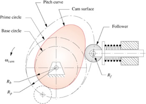
Figure: Base circle R b, high circle R p, and pitch curve of a radial cam with curler follower.
The high circle is best relevant to cams with curler fans or radiused (mushroom) fans and is measured to the middle of the curler follower. The high circle is described because the smallest circle which may be drawn tangent to the locus of the middle-line of the follower as proven in Figure 7-1 for a radial cam. The locus of the centreline of the follower is referred to as the pitch curve. Cams with curler fans are in truth described for manufacture with appreciate to the pitch
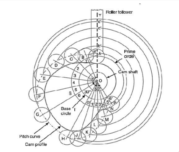
Profile of the cam when the line of stroke of the valve rod passes through the axis of the cam shaft. The profile of the cam, as shown in Fig, is drawn as discussed in the following steps:
a. Draw a base circle with center O and radius equal to the minimum radius of the cam (i.e. 25 mm)
b. Draw a prime circle with center O and radius, c.
OA = Minimum radius of cam + 1 2 Diameter of roller = 25 + 1 2 × 20 = 35 mm d. Draw angle AOS = 120º to represent raising or out stoke of the valve, angle SOT = 30º to represent dwell and angle TOP = 60º to represent lowering or return stroke of the valve.
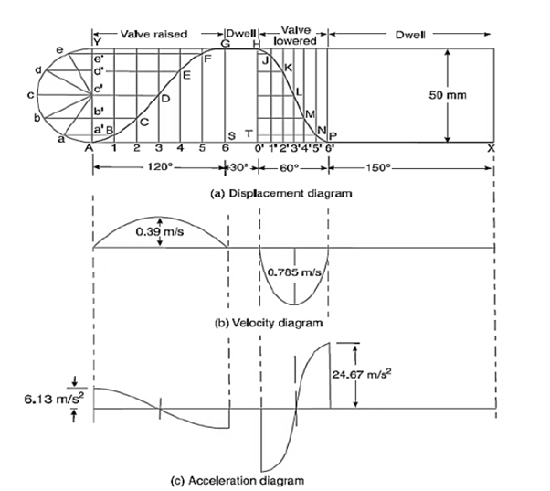
e. Divide the angular displacements of the cam during raising and lowering of the valve (i.e, angle AOS and TOP) into same number of equal even parts as in displacement diagram.
f. Join the points 1, 2, 3, etc. with the centre O and produce the lines beyond prime circle as shown in Fig 22.
g. Set off 1B, 2C, 3D etc. equal to the displacements from displacement diagram.
h. Join the points A, B, C …. N, P, A.
The curve drawn through these points is known as pitch curve.
i. From the points A, B, C …. N, P, draw circles of radius equal to the radius of the roller.
j. Join the bottom of the circles with a smooth curve as shown in fig 22. This is the required profile of the cam.
(a) profile of the cam when the line of stroke is offset 15 mm from the axis of the cam shaft: The profile of the cam when the line of stroke is offset from the axis of the cam shaft, as shown in fig 24 may be drawn as discussed in the following steps:
a. Draw a base circle with center O and radius equal to 25 mm.
b. Draw a prime circle with center O and radius OA = 35 mm
c. Draw an offset circle with center O and radius equal to 15 mm.
d. Join OA. From OA draw the angular displacement of cam i.e. draw angle AOS = 120º. Angle SOT = 30º angle TOP = 60º
e. Divide the angular displacements of the cam during raising and lowering of the valve into the same number of equal even parts (i.e. six parts) as in displacement diagrams.
f. From points 1, 2, 3 …. Etc on the prime circle draw tangents to the offset circle.
g. Set off 1B, 2C, 3D … etc. equal to displacements as measured from the displacement diagram.
h. By joining the points A, B, C … M, N, P. With a smooth curve, we get pitch curve.
i. Now A, B. C, etc. as center draw circles with a radius equal to the radius of roller.
j. Join the bottoms of the circles with a smooth curve as shown in fig 24. This is the required profile of the cam.
References:
1. Thomas Bevan, Theory of Machines, 3rd edition, CBS Publishers & Distributors, 2005.
2. CleghornW.L., Mechanisms of Machines, Oxford University Press, 2005.
3. Robert L. Norton, Kinematics and Dynamics of Machinery, Tata McGraw Hill, 2009.
4. Ghosh A. And Mallick A.K., Theory of Mechanisms and Machines, Affiliated East West Pvt. Ltd, New Delhi, 1988.