Unit - 5
Surface contacts
A floor-to-floor touch definition may be used as an opportunity to trendy touch to version touch interactions among particular surfaces in a version. Certain interplay behaviours may be described most effective via way of means of the usage of floor-to-floor touch.
For a short evaluation of floor-to-floor touch and different varieties of interactions to be had in Abaqus, see Understanding interactions, and About touch interactions. You can outline floor-to-floor touch in any step, which includes the preliminary step.
You can outline touch among edges of a cord or among faces of a stable or shell. Certain connectivity regulations follow to touch surfaces relying at the sort of touch formulation. You can deactivate a floor-to-floor touch interplay in a step and, if desired, reactivate this interplay in a next step.
You can deactivate the interplay in a step if it'll now no longer be wished with inside the evaluation. If you're developing a couple of floor-to-floor touch interactions, you can need to apply the touch detection device. This device automates the manner of choosing surfaces and lets in you to create a couple of interactions simultaneously.
For extra information, see Using touch and constraint detection. You can acquire touch statistics for a selected floor-to-floor touch interplay via way of means of the usage of the sphere and records output request editors with inside the Step module. In the Domain phase of the editors, pick out Interaction and pick out the call of the floor-to-floor touch interplay from the menu that appears. For extra information, see Creating an output request.
The technique for outlining floor-to-floor touch relies upon on whether or not you're acting an evaluation the usage of Abaqus/Standard or Abaqus/Explicit. This phase gives commands for the usage of the interplay editor to outline the special floor-to-floor touch options. They have highlighted that the set-up of interactions could have a dramatic impact at the stresses at contacts. In trendy, whilst touch stresses are of interest, attempt to abide via way of means of the subsequent fundamental rules: Ideally the slave floor ought to belong to the smallest floor, with the very best detail density and the softest body (thinking about each shape and cloth stiffness). If now no longer all the above may be achieved, it's miles extra critical to use the slave to the smallest floor with the better mesh density. If possible, extra correct consequences may be acquired via way of means of the usage of the floor to floor touch discretization technique over the node to floor technique.
The terrible consequences of irrelevant grasp–slave dating is much less critical for the floor to floor interplay type; but it's miles nevertheless ultimate to use the slave floor to the smaller floor with the better detail density. The subsequent touch associated weblog may be introduced to the with TECHNIA internet site quickly and could cowl using second-order factors in touch.
The floor to floor touch discretization technique makes use of the common slave node positions to implement every touch. Each touch constraint is biased in the direction of the nearest slave node however also bear in mind different may slave node positions. Figure 7 suggests that this technique can assist to mitigate a number of the problems related to the node to floor discretization technique. Figure eight suggests the equal evaluation however with the “correct” grasp-slave dating.
We can outline sliding friction because the resistance created with the aid of using any gadgets while sliding towards every other. This friction is likewise called kinetic friction and is described because the pressure this is had to hold a floor sliding alongside some other floor.
It relies upon on variables- one is cloth and the opposite is the burden of the object. Any extrude with inside the floor region in touch does now no longer extrude the sliding friction.
In maximum of the materials, sliding friction is much less than static friction.
There are exceptions that consist of metals having static and sliding friction coefficients and are basically the equal with small surfaces wherein molecular appeal forces take over.
Factors affecting sliding friction
- The floor deformation of gadgets.
- The roughness or smoothness of the floor of the gadgets.
- The unique pace of both object.
- The length of the object. Finally, the quantity of strain on both object.
Examples of Sliding Friction
Rubbing each the palms collectively to create heat.
A baby sliding down via a slide in a park.
A coaster sliding towards a table.
A washing gadget driven at the side of the floor.
The body and the brink of the door sliding towards one some other.
A block being slid throughout the floor.
Two playing cards in a deck sliding towards every other.
Sliding can arise among gadgets of arbitrary form while the rolling friction is the frictional pressure this is related to the rotational movement.
The values for the coefficient of rolling friction are pretty much less than that of sliding friction. It normally produces more sound and thermal bi-products. For example- Movement of braking motor car tires on a roadway.
For a transferring strong frame, there are predominant forms of friction that act upon it: The pressure resisting the movement of a rolling frame on a floor is referred to as rolling friction or rolling resistance. Rolling of ball or wheel at the floor is an instance of Rolling friction.
The different form of friction is sliding friction. In this form of friction, there may be a restrict at the frame’s motion as best one facet of the frame is in touch with the floor.
Pushing a field throughout the desk is an instance of Sliding friction. Rolling friction is extensively weaker than sliding friction.
Cause of Rolling Friction
When an item is rolled on a floor, positive matters happen:
The item is deformed on the factor of touch with the floor.
The floor is deformed on the factor of touch with the item.
The movement is created beneath the floor because of the above-noted points.
The number one motive of this friction is that the power of deformation is more than the power of recovery.
Also, there may be an adhesive pressure among the 2 surfaces which wishes to be conquer constantly.
The quantity of friction is primarily based totally on a range of things such as:
The pleasant of the sliding frame
The pleasant of the floor Load
The diameter of the rolling item
The floor vicinity of the frame
The machine is certainly a constantly variable transmission, through transferring the 2 disks positions the output ratio adjustments continually. Although as soon as utilized in early automobiles, nowadays the machine is maximum typically used on scooters, in particular go-peds, in vicinity of a series and tools machine.
It is robotically same to a ball-and-disk integrator, however supposed to address better torque levels. The machine includes disks, usually metal, set at proper angles to every other. One disk is attached to the engine, the alternative to the weight.
The load disk is located in order that its outer rim is pressed towards the pushed disk, and usually has a few kind of high-friction floor implemented to the outer rim to enhance torque switch. In early systems, paper and leather-based become regularly used for this floor. One of the disks, usually the weight side, is set up on a shaft that permits it to be moved on the subject of the pushed disk, permitting it to transport from a role on the middle of the pushed disk to its outer radius.
Moving the weight disk alongside this shaft adjustments the ratio of enter to output speed; while the weight disk is on the middle the output is zero, while it's miles on the outer rim, it's miles the ratio of the radius of the 2 disks. While robotically easy and offering a variable transmission that calls for no clutch, there are some of troubles with the layout that restriction its use.
The first is that the quantity of torque that may be transferred is a feature of the touch patch among the 2 disks, and therefore a feature of the width of the weight disk. Increasing this width improves torque handling, however then runs right into a 2nd problem.
As the "tools ratio" is a feature of the gap from the middle of the pushed disk, any finite thickness at the pushed disk approach the internal and outer edges are being pushed at specific speeds. This reasons tremendous friction at the bearing floor, carrying it out and giving off vast quantities of heat. This effects in a candy spot that limits it to positive low-torque roles.
Machine is a cluster of mechanisms that calls for supply of power to carry out positive challenge in a pre-described way. Household or business machineries are in the main pushed with the assist of high movers (which includes electric powered motor, windmill, hydraulic or steam turbine, inner combustion engine, etc.). Usually this high mover is positioned far from the device unit and rotates at better pace than it's far required in machines.
Mechanical energy transmission device is used to transmit energy from this high mover to the device unit. Such transmission device serves few simple purposes, which includes
(i) transmitting movement, torque and energy from motive force shaft to pushed shaft, (ii) reversing the course of rotation, like clockwise to counter-clockwise or vice versa, and
(iii) stepping up or stepping down the velocity of rotation. Mechanical energy transmission device includes 4 drives and few factors. Four drives are tools force, belt force, chain force, and twine force. Each of them has positive blessings over others.
They without delay take part in movement and energy transmission and manipulation to fulfil genuine requirement. They essentially retrieve energy from motive force shaft and switch it to the pushed shaft.
Such drives may be used from low-pace and low-energy applications (like mechanical watches, toys, etc.) to high-pace and heavy responsibility applications (which includes marine drives, energy plants, car differentials, etc.). On the opposite hand, energy transmission factors encompass shaft, key, coupling, brake, clutch, sprocket, pulley, etc. These factors are applied alongside force to facilitate clean and green energy transmission.
Bearings
A bearing is a system detail that constrains relative movement to simplest the favoured movement, and decreases friction among transferring parts. The layout of the bearing may, for example, offer at no cost linear motion of the transferring component or at no cost rotation round a set axis; or, it is able to save you a movement via way of means of controlling the vectors of ordinary forces that undergo at the transferring parts. Most bearings facilitate the favoured movement via way of means of minimizing friction.
Bearings are categorized widely in step with the kind of operation, the motions allowed, or to the instructions of the hundreds (forces) implemented to the parts. Rotary bearings keep rotating additives consisting of shafts or axles inside mechanical systems, and switch axial and radial hundreds from the supply of the burden to the shape assisting it.
The best shape of bearing, the apparent bearing, includes a shaft rotating in a hole. Lubrication is used to lessen friction. In the ball bearing and curler bearing, to lessen sliding friction, rolling factors consisting of rollers or balls with a round cross-phase are positioned among the races or journals of the bearing assembly.
A huge style of bearing designs exists to permit the needs of the software to be successfully met for max efficiency, reliability, sturdiness and performance.
Rolling bearings and sleeve bearings
In a sleeve or plain bearing, the axle and the bearing move in opposite directions on a sliding surface. By contrast, the two components of a rolling bearing that move towards one another – the inner and outer rings – are separated by rolling elements. This design generates significantly less friction than a sleeve bearing.
Radial bearings and axial bearings
Bearings can transmit loads in a radial direction or an axial direction (thrust) and in many cases there is a combination of both radial and axial loads to transmit.
Both designs are available as ball bearings or roller bearings. The choice of bearing design depends upon the application in question.
Lubrication
Although that is a legitimate definition, it fails to comprehend all that lubrication in reality achieves. Many unique materials may be used to lubricate a floor. Oil and grease are the maximum common. Grease consists of oil and a thickening agent to reap its consistency, whilst the oil is what in reality lubricates. Oils may be artificial, vegetable or mineral-primarily based totally in addition to a aggregate of these.
The utility determines which oil, typically known as the bottom oil, ought to be used. In severe situations, artificial oils may be beneficial. Where the surroundings is of concern, vegetable base oils can be utilized. Lubricants containing oil have components that enhance, upload or suppress houses in the base oil. The quantity of components relies upon at the kind of oil and the utility for which it will likely be used. For instance, engine oil may have a dispersant added. A dispersant continues insoluble depend conglomerated collectively to be eliminated through the clear out upon circulation. In environments that go through extremes in temperature, from bloodless to hot, a viscosity index (VI) improver can be added.
These components are lengthy natural molecules that live bunched collectively in bloodless situations and get to the bottom of in warmer environments. This system adjustments the oil’s viscosity and permits it to go with the drift higher in bloodless situations whilst nevertheless retaining its excessive-temperature houses. The handiest hassle with components is they may be depleted, and with the intention to repair them again to enough levels, commonly the oil extent should be replaced.
The number one features of a lubricant are to:
Reduce friction
Prevent put on
Protect the gadget from corrosion
Control temperature (expend warmth)
Control infection (deliver contaminants to a clear out or sump)
Transmit power (hydraulics)
Provide a fluid seal
Sometimes the features of lowering friction and stopping put on are used interchangeably. However, friction is the resistance to motion, and put on is the lack of cloth because of friction, touch fatigue and corrosion. There is a considerable difference. In fact, now no longer all that reasons friction (e.g., fluid friction) reasons put on, and now no longer all that reasons put on (e.g., cavitational erosion) reasons friction.
Reducing friction is a key goal of lubrication, however there are numerous different blessings of this system. Lubricating movies can assist save you corrosion through shielding the floor from water and different corrosive materials? In addition, they play a critical position in controlling infection inside systems. The lubricant works as a conduit wherein it transports contaminants to filters to be eliminated.
These fluids additionally resource in temperature manage through soaking up warmth from surfaces and shifting it to some extent of decrease temperature wherein it could be dissipated.
Types of Lubrication
There are 3 unique varieties of lubrication: boundary, blended and complete movie. Each kind is unique, however all of them depend on a lubricant and the components in the oils to defend towards put on.
Full-movie lubrication may be damaged down into forms: hydrodynamic and elastic hydrodynamic.
Hydrodynamic lubrication takes place while surfaces in sliding motion (relative to every different) are completely separated through a movie of fluid.
Elastic hydrodynamic lubrication is comparable however takes place while the surfaces are in a rolling motion (relative to every different). The movie layer in elastohydrodynamic situations is a good deal thinner than that of hydrodynamic lubrication, and the strain at the movie is greater. It is known as elastohydrodynamic due to the fact the movie elastically deforms the rolling floor to lubricate it.
Lubrication Types
Even at the maximum polished and easy surfaces, irregularities are present. They stick out of the floor forming peaks and valleys at a microscopic level. These peaks are known as asperities. In order for complete-movie situations to be met, the lubricating movie should be thicker than the period of the asperities. This kind of lubrication protects surfaces the maximum efficaciously and is the maximum desired. Boundary lubrication is observed wherein there are common begins off evolved and stops, and wherein shock-loading situations are present.
Mechanism which enables rotary motion of shaft to be transmitted to the second shaft axis, which is coincident with the first. OR
Clutch is a device to connect driving and driven shafts of a machine, where the driven shaft can be disconnected almost instantaneously from the driving shaft as desired by the operator or driver.
Requirements of clutch:
- Torque Transmission
- Gradual Engagements
- Heat Dissipation
- Dynamic Balancing
- Vibration Damping
- Size
- Inertia
- Ease of operation
1. Torque Transmission
- The clutch should be able to transfer the maximum torque of engine under all conditions.
- Usually designed to transmit 125 to 150% of maximum engine torque.
2. Gradual Engagement: Clutch should take the drive gradually without occurrence of sudden jerks.
3. Heat Dissipation: During clutch application large amount of heat is generated, the rubbing surfaces should have sufficient area and mass to absorb the heat generated. The design of clutch should ensure proper ventilation or cooling for adequate dissipation of heat.
The friction clutches work on the fact that friction is caused when two rotating discs come into contact with each other.
Principle for friction clutches:
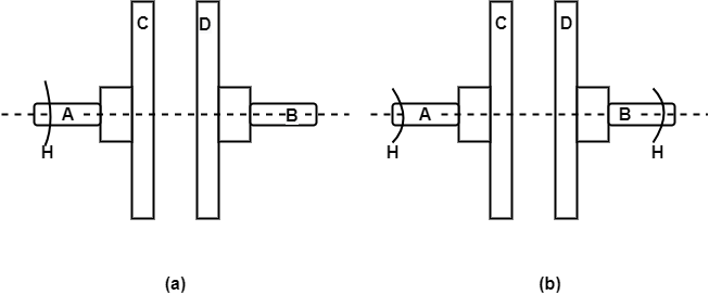
Figure 1: Principle for friction clutch
Let the shaft A and Disc C be revolving at some speed say N rpm. Shaft B and disc D keyed to it are stationary, initially when the clutch is not engaged.
Now apply some axial force W to disc D, so that it comes in contact with Disc C. As soon as the contact is made the force of friction between C and D will come into play and consequently the disc D will also start revolving.
The speed of D depends upon friction force present, which in turn is proportional to the force W applied.
If W is increased gradually, the speed of D will be increased correspondingly till the stage comes when speed of D becomes equal to speed of C.
Then clutch is said to be fully engaged.
Let W = axial load applied. µ= coefficient of friction R= effective mean radius of friction surface. Then, T = W R
Belt Drives:
The belt drive is used to transmit power from one shaft to another by means of pulleys which rotate at the same speed or at different speed.
I) Open and Cross belt drive
Open Belt Drive:
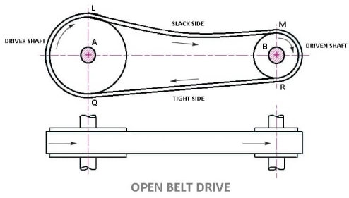
- In these types of belt drive, the belt is employing when the two parallel shafts have to rotate in the same direction.
- When the shafts are far apart, the lower side of the belt should be the tight side and the upper side must be the slack side.
- This is because, when the upper side becomes the slack side, it will sag due to its own weight and thus increase the arc of contact.
- In open belt drive, belt proceeds from top of one pulley to the top of other pulley without crossing.
- Contact angle (or wrap angle) between the belt and pulley is comparatively small (always below 180º in smaller pulley).
Length of Open Belt Drive Formula:
= π (r1 + r2) + 2x + (r1 – r2)2 /x ……………. (In terms of pulley radii)
= π/2 (d1 + d2) + 2x + (d1 – d2)2/ 4x ……….… (In terms of pulley diameters)
Cross Belt Drive
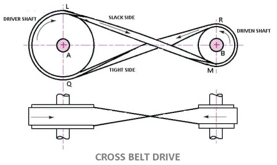
- In this type of belt drives, the belt is employing when two parallel shafts have to rotate in the opposite direction. At the junction where the belts cross, it rubs against itself and wears off.
- To avoid excessive wear, the shafts must be placed at a maximum distance from each other and operated at very low speeds.
- Contact angle between the belt and pulley is comparatively large (always above 180º in smaller pulley).
- In crossed belt drive, belt proceeds from top of one pulley to the bottom of other pulley and thus crosses itself.
- Here belt bends in two different planes in every rotation during its operation
- Cross belt drive can be advantageously applied for horizontal, inclined and vertical positions of driving and driven shafts.
- It can transmit more power as wrap angle is more.
Length of Cross Belt Drive
= π (r1+r2) + 2x + (r1+r2)2 /x …………… (In terms of pulley radii)
= π/2(d1+d2) +2x + (d1 + d2)2/ 4x …………(in terms of pulley diameters)
Material of belts:
The Materials used for belts and ropes must be strong, flexible, and durable. It must have high coefficient of friction: like
1- Leather belts
2- Cotton belts
3- Rubber belts
4- Balata belts
1. Leather belts:
The leather may be oak tanned or mineral salt tanned. Example chrome tanned. When the thickness of the belt required is more then, two or more strips are cemented together. Leather belts require periodic cleaning.
2. Cotton belts or Fabric belts:
Fabric belts are made by folding canvas or cotton ducks in layers and stitching together. The fabric belts are cheaper and best suited in warm climates, damp atmospheres. These are mostly used in Farm machinery, belt conveyor etc.
3. Rubber belts:
Rubber belts are made of Fabric with rubber layer. Rubber belts are used in sawmills, paper mills, etc.
4. Balata Belts:
Balata belts are similar to rubber belts except that balata gum is used in place of rubber. Balata belts are acid proof and water proof and it is not affected by animal oils or alkalis. The balata belts should not be at temperatures above 40° C because at this temperature the balata begins to soften and becomes sticky. The strength of balata belts is 25 percent higher than rubber belts.
Type of belts:
Different types of belt are as follows
- Flat Belt
- V – Belt
- Circular Belt

1. Flat Belt:
Flat belt has a rectangular cross section. Flat belts are capable of transmitting power over long distance between pulley centres. The efficiency of this drive is around 98 % and produces less noise.
This belt is mostly used in factories and workshops, where a moderate amount of power is to be transmitted, from one pulley to another when two pulleys are not more than 8 metres apart.
Flat belts drives are of following types:
- Open belt drive.
- Cross belt drive.
- Stepped or cone pulley or speed cone drive.
- Fast and loose pulleys.
- Jockey pulley drive or belt drive with idler pulley
- Compound Belt Drive System
2. V – Belt:
V-Belts also used with grooved pulleys, V-belts are trapezoidal in cross section. V-belts permit large speed ratios and can transmit higher power. Multiple drives are possible.
This belt is mostly used in factories and workshops, where a moderate amount of power is to be transmitted, from one pulley to another when two pulleys are very near to each other.
3. Circular Belt or Round Belt:
Circular Belt or Round belt has a circular cross section and is used with grooved pulleys, This belt is mostly used in factories and workshops, where a great amount of power is to be transmitted, from one pulley to another when two pulleys are more than 8 metres apart.
Length of belt of open and cross drive:
Length of Open belts drive:
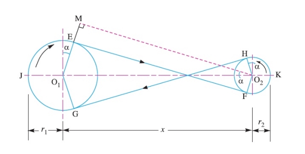
We have discussed that in an open belt drive, both the pulleys rotate in the same direction as shown in Fig.
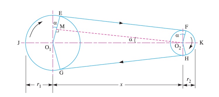
Let r1 and r2 = Radii of the larger and smaller pulleys,
x = Distance between the centres of two pulleys (i.e. O1O2), and
L = Total length of the belt.
Let the belt leaves the larger pulley at E and G and the smaller pulley at F and H as
Shown in Figure. Through O2 draw O2M parallel to FE.
From the geometry of the figure, we find that O2M will be perpendicular to O1E.
Let the angle MO2O1 = α radians.
We know that the length of the belt,
L = Arc GJE + EF + Arc FKH + HG
= 2 (Arc JE + EF + Arc FK) ……………………..(i)
From the geometry of the figure, we also find that
Sin α = O1M/O1O2 = O1E – EM / O1O2 = r1 – r2 / x
Since the angle α is very small, therefore putting
Sin α = α (in radians) = r1 – r2 / x …………………….(ii)
∴ Arc JE = r1 (π/2 + α) ………………………….(iii)
Similarly, arc FK = r2 (π/2 – α) ……………………..(iv)
And EF = MO2 = [(O1O2)2 – (O1M)2]0.5
= [x2 – (r1 – r2)2]0.5
= x [1 – {(r1-r2) /x }2 ]0.5
Expanding this equation by binomial theorem, we have
EF = x [1 – {0.5 {(r1 – r2)/x} + …] = x – (r1 – r2)2 /2x …………………..(v)
Substituting the values of arc JE from equation (iii), arc FK from equation (iv) and EF from equation (v) in equation (i), we get
L = 2 [r1(π/2 +α) + x – {(r1-r2)2/2x} + r2(π/2 -α)]
= 2 [{r1 × π/2} + {r1×α} + x – {(r1- r2)2/2x} + {r2 × π/2} - {r2×α}]
= 2 [π/2(r1+r2) + α(r1-r2) +x – {(r1-r2)2/2x}]
= π(r1+r2) + 2α(r1-r2) +2x – {(r1-r2)2/x}
Substituting the value of α = (r1-r2)/x from equation (ii), we get
L = π(r1+r2) + 2{(r1-r2)/x}{(r1-r2)} +2x – {(r1-r2)2/x}
= π(r1+r2) + 2{(r1-r2)2/x} + 2x – {(r1-r2)2/x}
= π (r1 + r2) + 2x + (r1 – r2 )2 /x ……………. (in terms of pulley radii)
= π/2 (d1 + d2) + 2x + (d1 – d2)2 /4x …… (in terms of pulley diameters)
Length of cross belt drive:
We have discussed that in a cross belt drive, both the pulleys rotate in the opposite directions as shown in Fig
Let r1 and r2 = Radii of the larger and smaller pulleys,
x = Distance between the centres of two pulleys (i.e. O1O2 ), and
L = Total length of the belt.
Let the belt leaves the larger pulley at E and G and the smaller pulley at F and H as shown in Figure.
Through O2 draw O2M parallel to FE.
From the geometry of the figure, we find that O2M will be perpendicular to O1E.
Let the angle MO2O1 = α radians.
We know that the length of the belt,
L = Arc GJE + EF + Arc FKH + HG
= 2 (Arc JE + FE + Arc FK) …………………(i)
From the geometry of the figure, we find that
Sin α = O1M/O1O2 = (O1E + EM)/O1O2 = r1+r2 / x
Since the angle α is very small, therefore putting
Sin α = α (in radians ) = r1+r2 / x ………………………….…(ii)
Arc JE = r1 (π/2 + α) ………………. ……(iii)
Similarly, arc FK = r2 (π/2 + α) …………………(iv)
EF = MO2 = [(O1O2 )2 – (O1M)2]0.5
= [x2 – (r1 + r2 )2]o.5
= x [1- (r1+r2 /x )2 ]0.5
Expanding this equation by binomial theorem, we have
EF = x [1- 1/2(r1+r2 /x)2 + …] = x – [(r1+r2)2/2x] ……………………(v)
Substituting the values of arc JE from equation (iii), arc FK from equation (iv) and EF from equation (v) in equation (i), we get,
L = 2 [r1(π/2 +α) + x – {(r1+r2)2/2x} + r2(π/2 +α)]
= 2 [{r1 × π/2} + {r1×α} + x – {(r1+r2)2/2x} + {r2 × π/2} + {r1×α}]
= 2 [π/2(r1+r2) + α(r1+r2) +x – {(r1+r2)2/2x}]
= π(r1+r2) + 2α(r1+r2) +2x – {(r1+r2)2/x}
Substituting the value of α = (r1+r2)/x from equation (ii), we get
L = π(r1+r2) + 2{(r1+r2)/x}{(r1+r2)} +2x – {(r1+r2)2/x}
= π(r1+r2) + 2{(r1+r2)2/x} + 2x – {(r1+r2)2/x}
= π (r1+r2) + 2x + (r1+r2)2 /x …………… (In terms of pulley radii)
= π/2(d1+d2) +2x + (d1 + d2)2/ 4x …………(in terms of pulley diameters)
Rope drive-
Rope drive is used where a large amount of power is needed to transfer for a long distance (more than 8m). The rope runs over a grooved pulley.
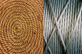
There are two types rope drive Fibres Rope and Wire Rope.
Advantages of the rope drive
- Significant power transmission.
- It can be used for long distance.
- Ropes are strong and flexible.
- Provides smooth and quiet operation.
- It can run any direction.
- Low-cost and economic.
- Precise alignment of the shaft not required
Disadvantages of the rope drive
- Internal failure of the rope has no sign on external, so it if often get unnoticed.
- Corrosion of wire rope.
How is rope drive different from Belt drive and Chain drive?
A Rope Drive uses a rope to transmit power from one system to another, for e.g. In pulleys over a well. It is different from a belt drive because it does not use a belt to transmit power. A rope drive is expected to give a smoother operation and less noise than chain drive, but can have higher power losses.
Brake refers to a tool that in general performs the function of slowing down or bringing to a halt an item in movement including a vehicle, a bike, train, an airplane, or roller-coaster. One of the maximum mentioned braking structures are those utilized in vehicles. A friction brake plays its characteristic through urgent a brake pad towards the shifting component.
As a end result of it, a friction pressure opposing the course of the shifting component develops. In the process, warmness is generated from the kinetic power of the shifting item. The phenomena of friction in braking structures had been notably blanketed on account that the start of the twentieth century. The reputation of the subject emanates from the belief that brakes constitute one of the essential protection additives in cars and their failure should cause catastrophic consequences.
During the complete braking action, it's far important that the friction pressure is excessive and stable. This ought to practice to any circumstance consisting of a extensive variety of touch temperatures, touch pressures and relative velocities among the static and shifting elements of the break, consisting of any environmental changes.
Manufacturers commonly cognizance at the layout and development of the substances used with inside the brakes (each the static and dynamic additives). In the current years, greater green braking structures which are cost-powerful, lighter, and smaller with a excessive ability for the conversion of kinetic power to warmness have reached the auto market.
Additionally, different parameters are in recent times considered: environmental friendliness, excessive balance with minimum want for maintenance, and advanced reliability. The brake structures shape has turn out to be notably standardized over time.
Nevertheless, unique matters want to be finished to maximum designs including modeling, significant testing, and overall performance calculations earlier than very last approval as consistent with criminal requirements and corresponding guidelines. The guidelines and requirements range amongst numerous countries, however the protection and reliability of the brakes are of challenge everywhere.
The bodily residences of the additives decide the layout of the brakes as they may be in splendid component accountable of the friction era, the warmth dissipation, and in the end the powerful preventing because of friction. Their put on resistance determines the lifespan of the brakes.
It is really well worth noting that friction and put on are machine residences that are hard to degree and conclusions derived from the exams ought to be assessed through certified iridologists. The layout of friction brakes ought to be choicest in numerous aspects:
(1) Performance in friction and overall performance, which particularly is predicated at the coefficient of friction and the regular strain carried out while bringing surfaces together,
(2) Durability,
(3) To be had area for installation, and
(4) The As already mentioned, friction-brought on vibrations and related noise are crucial elements to keep in mind while designing brakes. Currently, giant enhancement of noise era has been done through editing the floor roughness and chemistry on the touch.
References:
1. Thomas Bevan, Theory of Machines, 3rd edition, CBS Publishers & Distributors, 2005.
2. CleghornW.L., Mechanisms of Machines, Oxford University Press, 2005.
3. Robert L. Norton, Kinematics and Dynamics of Machinery, Tata McGraw Hill, 2009.
4. Ghosh A. And Mallick A.K., Theory of Mechanisms and Machines, Affiliated East West Pvt. Ltd, New Delhi, 1988.