Unit - 4
Steering geometry
- Ackerman steering geometry is a geometric arrangement of linkages in the steering of a car or other vehicle designed to solve the problem of wheels on the inside and outside of a turn needing to trace out circles of different radii.
- The intention of Ackermann geometry is to avoid the need for tires to slip sideways when following the path around a curve.
- Intersecting the axes of the front wheels on this line as well requires that the inside front wheel be turned, when steering, through a greater angle than the outside wheel.
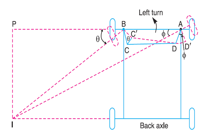
Fig 1. Ackerman steering geometry
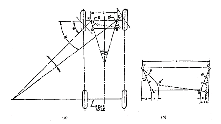
Fig 2. Ackermann steering mechanism.
(a) Outline of mechanism
(b) Details of enlarged scale
Let l = length of track rod, and
r = length of links RA and SB
Then referring Fig. 27 (b) and neglecting the obliquity of the track rod in the turned position, the movements of A and B in the horizontal direction may be taken to be same (each equal to 'x')
Then, sin (α + θ) = (y + x)/r
And, sin (α – φ) = (y – x)/r
On adding,
Sin (α + θ) + sin (α – φ) = 2y/r = 2sin α
The mechanism gives only 3 positions for correct steering; one when θ = 0 and the other two each corresponding to the turn to right or left (at a fixed turning angle). However, for other angles also it gives a close approximation to the ideal condition.
Further this has the advantage that it employs pivots and not sliding constrains, due to which reason its maintenance is easier. That is why it is universally employed. However, lately the automobile designers do not care to follow the Ackermann mechanism very strictly on account of the improvement in the suspension and tyres.
Any small deviation from the true rolling angles can be readily corrected by the tyres sidewall flexibility and tread distortion. Rather it is endeavoured to obtain the smallest value of the turning circle.
It may be noted that while parking, it is easier to steer a vehicle in reverse than in the forward direction because the rear wheels turn on smaller radius than the front wheels.
Example
The front axle of a car has pivot centres 1 1 m apart. The length of each steering arm is 150 mm, while the track rod is of 1.0 metre length. Calculate the wheelbase for perfect rolling of the car wheels when the inner wheel stub axle is at 55° to the rear centre line.
Solution.
Referring fig. 27(a),
θ = 90 – 25 = 35°
r = 150mm = 0.15m
l = 1.0m
c = 11m
Sin α = (c - l)/2r = (1.1 - 1.0)/ (2 x 0.15) = 0.333
α = 19.45°
From Equation (8.6),
Sin (19.45° + 35°) + sin (19.45° - φ) = 2 sin 19.45°
i.e. 0.814 + sin (19.45° - φ) = 0.667
φ = 27.9°
From equation of correct steering,
Cot φ – cot θ = c/b
Cot 27.9° - cot 35° = 1.1/ b
1.888 – 1.428 = 1.1/b
Wheel base, b = 2.39m
Key Takeaways:
- Outside of a turn needing to trace out circles of different radii.
- However, for other angles also it gives a close approximation to the ideal condition.
- Rather it is endeavored to obtain the smallest value of the turning circle.
- Worm and Wheel Steering Gear.
- Worm and Roller Steering Gear.
- Re-circulating Ball type Steering Gear.
- Rack and Pinion type Steering Gear
- Cam and Peg Steering Gear.
- Cam and Double lever Steering Gear.
- Worm and Sector Type Steering Gear.
1. Worm and Wheel Type:
This form of steerage equipment has a rectangular reduce screw threads on the quit of the steerage column; which paperwork a Trojan horse, on the quilt of it a Trojan horse wheel is outfitted and works rigidly with it.
Generally included shaft is used for the trojan horse wheel.
The trojan horse wheel may be became to a brand new role the drop arm may be readjusted to the best running role.
2. Re-circulating Ball Type:
In this form of equipment field the infinite chain of balls are furnished among the computer virus and nut members.
The nut shape a hoop of rack having an axial movement.
So that the arena at the rocker shaft racks, the balls roll constantly among the computer virus and nut.
Being furnished with go back chambers on the ends of the computer virus.
3. Rack and Pinion Type:
In this kind of steerage a pinion is supplied the lowest stop of the steerage column.
The enamel of the pinion wheel in mesh with corresponding enamel supplied at the rack, the stop of that are linked to the stub axle via the rod.
The rotating movement of the pinion operates the rack in FORE and AFT course which in flip operates the stub axle.
4. Cam and Lever Type:
The cam and lever guidance makes use of one or lever studs outfitted in taper curler bearing.
When the computer virus with inside the shape of helical groove rotates the stub axle and it additionally rotates together with it.
This imports a turning movement to the drop arm shaft.
5. Worm and Sector Type:
- In this kind the trojan horse at the give up of the guidance shaft meshes with a zone installed on a zone shaft.
- When the trojan horse is turned around through rotation of the guidance wheel, the arena additionally flip rotating the arena shaft.
- Its movement is transmitted to the wheel thru the linkage.
- The zone shaft is connected to the drop arm or pitmen arm.
6. Cam and Peg Steering Gear:
- This sort of steerage box, in vicinity of worm, a cylindrical shaft, supported with the aid of using curler bearing with inside the housing.
- The cylindrical shaft carried a deep spiral groove, commonly a variable pitch on its floor among its bearing and this shaft is called a cam.
- A necessary rocker arm and shaft is located half-manner alongside the cam. At the unfastened quit of the rocker arm a conical peg is equipped which engages the groove.
Key Takeaways:
- Generally included shaft is used for the trojan horse wheel.
- This imports a turning movement to the drop arm shaft.
- Its movement is transmitted to the wheel thru the linkage.
- An necessary rocker arm and shaft is located half-manner alongside the cam.
Working of Power Steering
The strength guidance unit is positioned on the decrease give up of the guidance column in location of the standard traditional guidance gear. It is hooked up with the aid of using oil strains to the hydraulic pump established at the generator. The pump with a comfort valve avoids immoderate oil pressures.
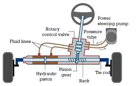
Fig 3. Power steering Unit
The power steering unit has:
- A valve frame with 4 valves.
- Two electricity cylinders have pistons one on every side.
The Valves will supply the oil to assist in creating a turn. This works at the endwise motion of the guidance column shaft. The guidance wheel rotates the bug. Thus it imposes cease-sensible thrust (both up and down) at the bug as according to the course of rotation. This creates the motion of the guidance column shaft via a small fraction of an inch.
This motion admits oil beneath Neath strain in a single or the opposite cease of the electricity cylinder. This makes the piston flow in a single or any other course. This movement is carried to the pitman shaft via the rack and pinion arrangement.
Electric Power Steering:
- An electricity steerage is a mechanical tool prepared on a motor automobile that facilitates drivers steer the automobile with the aid of using augmenting steerage attempt wished to show the steerage wheel, making it less complicated for the automobile to show or manoeuvre at decrease speeds.
- Hydraulic or electric powered actuators upload managed power to the steerage mechanism, so the driving force can offer much less attempt to show the instructed wheels while using at standard speeds, and decrease drastically the bodily attempt essential to show the wheels while a automobile is stopped or transferring slowly.
- Power steerage also can be engineered to offer a few synthetic remarks of forces appearing at the instructed wheels. Hydraulic electricity steerage structures for vehicles increase steerage attempt thru an actuator, a hydraulic cylinder this is a part of a servo gadget.
- These structures have an immediate mechanical connection among the steerage wheel and the linkage that steers the wheels. This method that electricity-steerage gadget failure (to reinforce attempt) nevertheless lets in the automobile to be instructed the use of guide attempt alone.
Hydraulic Power Steering:
- The winning kind of energy steerage from the Nineteen Fifties to the early 2000s became hydraulic help.
- Hydraulic energy steerage uses, as its call indicates, hydraulic fluid it's pressurized through a pump pushed off the engine.
- Although it served the car global properly for the ones 50 years, there are some downsides to this kind of system: there may be wasted energy, for the reason that pump is jogging continuously, even if the automobile is using instantly and there may be no help needed.
- Plus, the hydraulic fluid desires to get replaced periodically, and if any of the hydraulic strains springs a leak, it now no longer best makes a mess, however the energy help is lost.
Key Takeaways:
- The pump with a comfort valve avoids immoderate oil pressures.
- Thus it imposes cease-sensible thrust (both up and down) at the bug as according to the course of rotation.
- The winning kind of energy steerage from the Nineteen Fifties to the early 2000s became hydraulic help.
- These structures have an immediate mechanical connection among the steerage wheel and the linkage that steers the wheels.
A stay the front axle, in comparison to the useless axle, has the extra characteristic of transmitting the using energy taken from a switch gearbox to the front wheels having an exceptional swivelling mechanism. The stay the front axles even though similar to the equipment axles have a few distinction on the axle 1/2 of shafts stop in which the wheels are mounted. A useless the front axle has sufficient tension and electricity to hold the burden of the automobile from the springs to the front wheels.
Front wheels of the car are established on the front axles. Functions of the front axle are listed below:
(a) It helps the load of the front a part of the car.
(b) It allows steering.
(c) It absorbs torque carried out on it because of braking of car.
Construction and Operation
Front axle is made from I-phase within side the centre component and round or elliptical phase on the ends. The unique x-phase of the axle makes it capable of withstand bending hundreds because of weight of the car and torque carried out because of braking.
There are two types of front axles:
(a) Dead front axle, and
(b) Line front axle.
Dead Front Axle
These axles have enough rigidity and electricity to take the weight. The ends of the front axle are definitely designed to accommodate stub axles.
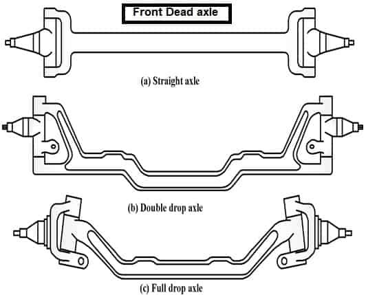
Fig 4: Dead Front Axle
Line Front Axle
- Line axles are used to transmit strength from tools container to the front wheels.
- Line the front axles despite the fact that, the front wheels.
- Line the front axles despite the fact that resemble rear axles but they may be specific on the ends wherein wheels are mounted.
- Maruti-800 has line the front axle.
Key Takeaways:
- A useless the front axle has sufficient tension and electricity to hold the burden of the automobile from the springs to the front wheels.
- Front axle is made from I-phase within side the centre component and round or elliptical phase on the ends.
- The ends of the front axle are definitely designed to accommodate stub axles.
Wheel alignment occasionally known as breaking, or monitoring is a part of widespread vehicle upkeep that includes adjusting the angles of wheels to the auto producer specs.
The motive of those modifications is to lessen tire put on and to make sure that car tour is instantly and true (without "pulling" to at least one side). Alignment angles also can be altered past the maker's specs to achieve a selected coping with characteristic.
Motorsport and off-street programs might also additionally name for angles to be adjusted properly past every day, for a whole lot of reasons. Camber is the perspective which the vertical axis of the wheel makes with the vertical axis of the car.
This perspective could be very vital for the cornering overall performance of the motors. Generally a Camber round 0.5-2 stages is given at the motors. Depending upon wheel orientation, Camber may be of 3 types.
1. Positive Camber
The Camber might be known as nice whilst the pinnacle of the wheels lean outwards. Positive Camber is usually utilized in off-street motors. This is due to the fact, it improves the guidance reaction and reduces the guidance efforts required for turning the car.
Positive Camber is likewise furnished in load sporting motors. This is due to the fact the heavy load on those motors reason outward leaning wheels to straighten up, enhancing the car stability.
2. Zero Camber
The car is stated to have 0 Camber whilst the wheels stand flawlessly instantly at the floor.
3. Negative Camber
Negative Camber is encountered whilst the pinnacle of the wheels lean inwards. Providing Negative Camber improves the cornering overall performance. When the car activates a corner, it plays a round motion. Hence, it reports same and contrary centripetal & centrifugal forces.
The centripetal pressure is skilled with inside the shape of friction on tyres. The centrifugal pressure skilled via way of means of the auto attempts to throw it far from the turning centre. This will increase the everyday response at the outer wheels. Due to boom in everyday response, the frictional pressure at the outer tyres additionally boom.
This friction acts as centripetal pressure and attempts to bend the outer tires inwards. The tires get deformed because of bending and the touch region among the wheels and the floor decreases. This in turns decreases the frictional pressure among the outer tires and the floor inflicting the car to glide at some point of cornering.
Hence a bad Camber is given to the motors. The negatively cambered wheels lean inwards. So at some point of cornering whilst the frictional forces try and deform the outer wheels, they simply absolutely get flat on floor growing the friction with street surface.
Two of the motives why current automobiles are as cushty as they're need to do with now no longer best the manner the suspension structures are configured, however additionally with how suspension structures on current automobiles are connected to the automobile.
While those elements offer a clean trip, this clean trip comes on the value of elevated complexity that may make the manner of aligning all of the wheels nicely, a hard one at times. As a realistic matter, a complete wheel alignment process on a current automobile includes numerous tremendously separate operations, those being-
Toe- in / Toe-out adjustment
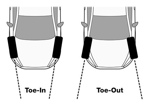
On passenger cars, those situations are normally due to phrase or broken guidance components, worn or broken manage arm bushing, or the over-, or beneathneath adjustment of tie rod ends. On cars that use guidance bins rather of guidance racks, those situations also can be due to the above, further to broken, worn, or bent drag hyperlinks and/or worn loafer arm bushings.
Camber adjustment
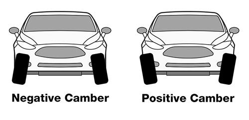
These situations are normally due to worn, broken, or damaged McPherson strut mountings, worn, broken, or damaged manage arm bushings, or through lateral touch with obstacles.
Caster adjustment
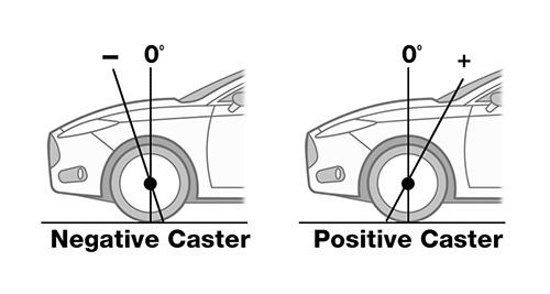
Note that whilst this putting is important for proper directly-line tracking, it's far typically now no longer feasible to regulate this attitude.
However, deformation of the frame due to an twist of fate can disturb this putting, that can occasionally be corrected through a frame restore keep that may “pull” the chassis lower back into form with computerised equipment.
Four wheel adjustment
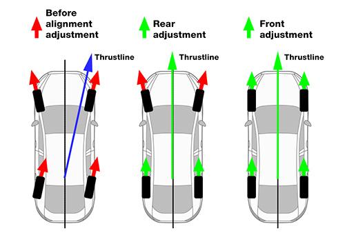
The photograph above indicates all of the modifications required to make sure that each one the wheels on an automobile are nicely aligned to every other, in addition to the centreline of the automobile, that is usually known as the “thrust line”.
Although this form of process is maximum usually done on effective high-stop sports activities automobiles to make sure that the auto’s dealing with traits aren't compromised, many “ordinary” automobiles can gain substantially from this process as well. If the process is done through a certainly certified technician, this process produces the great outcomes in phrases of alignment accuracy.
Thrust line adjustment
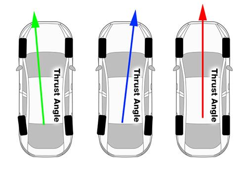
In the panel above, the purple line represents the thrust attitude, which have to run at a proper attitude via the period of the auto relative to the centreline of the rear axle, and if this putting is correct, the front wheels are aligned to this line.
However, if the centreline of the rear axle isn't always at proper angles with the thrust line, the misaligned rear axle (as proven through the inexperienced and blue lines) will pressure the rear wheels now no longer to comply with the front wheels, and chronic counter guidance is needed to hold the automobile shifting in a directly line.
Thrust line adjustment consequently entails realigning the rear axle with the thrust line to make sure that the rear wheels run with inside the identical line because the front wheels without the want to use a corrective guidance input.
Key Takeaways:
- This will increase the everyday response at the outer wheels. Due to boom in everyday response, the frictional pressure at the outer tyres additionally boom.
- As a realistic matter, a complete wheel alignment process on a current automobile includes numerous tremendously separate operations, those being-
The Double Wishbone suspension additionally has an unbiased design, so the turning perspective and suspension motion will now no longer have an effect on the geometry perspective, due to the fact the perspective will stay constant. The Double Wishbone suspension has drawbacks because of the pretty big area it requires. On pinnacle of that, whilst you need to update a surprise breaker or surprise absorber, the disassembly manner takes a protracted time.
To keep away from diverse harm to the car, you could do spooring regularly.
1. Rigid Axle Suspension
The important characteristic of this suspension is its wheels at the rear left and right. The wheels are linked into one axle that is usually called the axle. The inflexible axle suspension has 2 fashions at once, particularly the Axle Rigid version that is ready with leaf springs, and the Axle Rigid version that is ready with a coil spring or regularly called a spring.
- This suspension has pretty right exceptional and may be implemented in diverse forms of cars.
- It in all fairness easy due to the fact it could paintings with simply one stable piece and is geared up with 2 springs.
- Suspension can assist hose down the vibrations or shocks that arise while you are on a avenue this is choppy or has a tendency to be bumpy.
With a very good exceptional suspension vehicle, you could live seated with none disruption. The suspension isn't always handiest beneficial to assist lessen vibrations while the auto is riding however could make managing more secure and permit the auto can run stably at the avenue. With its very sizable use, of course, the suspension is a have to-have aspect in a vehicle and it have to get more care.
2. Macpherson Suspension
Macpherson is a suspension whose call is taken from its inventor, Earle Macpherson. Lots of automobiles round the sector use Macpherson suspension. Many automobile producers like this suspension, as it has an lower priced rate and additionally has pretty easy components.
- This suspension is likewise very clean to reap as it’s allotted widely.
- The drawback of Macpherson’s suspension is that it's far much less capable of get hold of hundreds and the lean perspective constantly modifications while the auto is became or turns, this makes the tires much less capable of grip the street asphalt properly.
3. Double Wishbone Suspension
Double Wishbone is a kind of suspension that has 2 palms that help the suspension system, specifically the higher and decrease palms. With this suspension, the automobile can run stably.
4. Independent Suspension
Independent suspension is a specifically designed suspension due to the fact the proper and left wheels on the rear aren't linked immediately however alternatively via way of means of axle joints If the rear wheel steps on a hole, of course, the automobile will now no longer rock and that is due to the fact most effective the left suspension moves.
- Independent suspension is certainly extensively utilized in luxurious cars.
- The unbiased suspension has a extra complicated creation and the axle moves are at the same time unbiased.
This suspension is likewise ready with bendy joints. This sort of suspension remains pretty expensive, so its use is ordinarily in costly cars. You also can experience the consolation of the Independent Suspension whilst riding the Wuling Cortez CT Type S. This own circle of relative’s vehicle from Wuling gives consolation via Independent Suspension at the rear wheels.
5. Rigid suspension – Leaf Spring
Rigid – Leaf spring is one form of suspension this is extensively carried out in vehicles circulating in Indonesia and is typically utilized in business kind vehicles or vintage kind vehicles.
- This suspension is normally used on the rear of the auto due to the fact this suspension is stiff.
- This suspension has a reasonably easy and easy construction.
- Cars that use this suspension normally have a reasonably excessive degree of resistance.
6. Trailing Arm Suspension
Trailing Arm is a sort of suspension whose commands are nearly similar to three Links – Rigid, despite the fact that the running machine could be very distinct. The manner it really works is likewise distinct from the three Links – Rigid or different styles of suspension. The Trailing Arm suspension has linked from the proper facet to the left. This sort of suspension is typically located behind the car.
7. Air Suspension
Air Suspension is one of the advanced suspensions that has extremely good performance, so this sort of suspension is broadly utilized in luxurious cars. Even in luxurious cars, the automobile’s suspension may be adjusted the usage of a laptop and this permits the adjustment to be executed properly. The downside of this suspension is that it has a completely complex production whilst as compared to different styles of suspension. Not handiest that, however this suspension additionally has a completely luxurious price. Those are the 8 styles of automobile suspensions that exist today. Hopefully, this statistics can upload in your car knowledge.
Key Takeaways:
- This suspension has pretty right exceptional and may be implemented in diverse forms of cars.
- Macpherson is a suspension whose call is taken from its inventor, Earle Macpherson.
- Independent suspension is certainly extensively utilized in luxurious cars.
- The Trailing Arm suspension has linked from the proper facet to the left.
- The downside of this suspension is that it has a completely complex production whilst as compared to different styles of suspension.
References:
- Automotive Engineering- Hietner.
- Automobile Engineering - Narang.
- Automobile Engineering – Dr. Kirpal Singh
- Automotive Mechanics- Crouse.